

isel Germany AG
isel Germany AGisel Germany AG
isel Germany AG, D-
36124 Eichenzell, Buergermeister
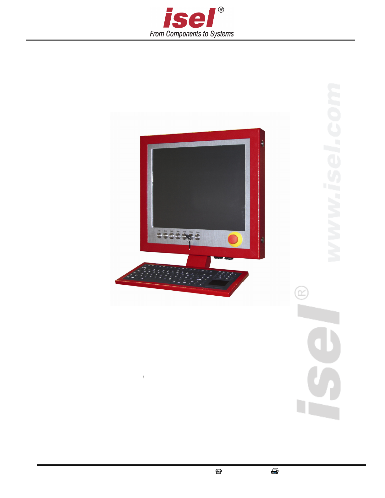
CNC control panel iOP
Operating
-Ebert-Str. 40 +49 (0)6659 981-0
-19-
TFT
instructions
+49 (0)6659 981-776
Abbreviations used in these
operating instructions
MRL
Machinery Directive 2006/42/EC
ERL
EMC Directive 2004/108/EC
NRL
Low Voltage Directive 2006/95/EC
Symbols used
The operating instructions contain important information / issue and danger symbols, which
must be noted and complied with:
Warning!
This symbol warns of potential danger to health, life and limb.
Warning! Potentially lethal voltage
This sign warns of danger to life and limb due to the presence of high-voltage
electrical circuits. Failure to observe the danger can result in severe injury or
death.
Attention!
This symbol means important instructions are being given. Failure to observe the
instructions may result in equipment malfunction or damage to machinery.
Information:
This symbol means important information or advice is being given.
Complying with safety information
Prior to using the iOP-19-TFT CNC control panel or making any alterations to
the electrical installations in or on your machinery, please ensure that you have
carefully read through the safety information in these operating instructions.

The information, technical specifications and dimensions contained in this booklet represent the
latest available data at the time of going to print. The occurrence of misprints and other errors
cannot, however, be completely ruled out. We thank you in advance for bringing such errors to
our notice and we welcome any improvement suggestions you may have.
We are obliged to draw your attention to the fact that the software and hardware brand names
and trade marks appearing in this booklet are protected under patent.
All rights reserved. No part of this booklet may be reproduced, electronically processed,
duplicated or distributed in any form whatsoever (printed out, photocopied, etc.) without the
written permission of isel Germany AG.
isel Germany AG
isel Germany AG isel Germany AG
isel Germany AG
machines and controllers are CE compliant and labelled
accordingly. This equipment must not be operated until the CE safety guidelines
applying to all associated machinery parts and components have been
fully complied with.
isel Germany AG
isel Germany AG isel Germany AG
isel Germany AG accepts no liability for damage to equipment or malfunction
where modification has been made to the controller.
The EMC test is only valid for CNC control panels with original ex-works
configurations.
Manufacturer: isel Germany AG
Buergermeister-Ebert-Straße 40
D-36124 Eichenzell
Tel.: +49 (0) 6659 981-0
Fax: +49 (0) 6659 981-776
Email: automation@isel.com
http://www.isel.com
Article No. : 371100 1000 (original operating instructions)
Date of issue: 06/2014_RL
Technical specifications may change without prior notification.
Current operating instructions and equipment manuals can be downloaded at:
www.isel-data.de/manuals

Table of contents
1 General Information ........................................................................................................... 5
1.1 Safety information .............................................................................. …………………5
2 Product description ............................................................................................................. 6
2.1 Versions .......................................................................................................................... 6
2.1.1 CNC control panel iOP-19-TFT with 19“ touch screen ....................................................... 6
2.2 Description of control elements ..................................................................................... 7
3 Connections of the control elements ................................................................................ 10
3.1 Connection of the controls for the control PC .............................................................. 10
3.2 Power supply for the CNC control panel ..................................................................... 11
3.3 Connection of machine controls ................................................................................... 12
4 Faults .................................................................................................................................. 13
5 Service and maintenance .................................................................................................. 13
6 Technical Data ................................................................................................................... 14
6.1 Technical Data iOP-19-TFT ......................................................................................... 14
7 EC Declaration of Conformity ......................................................................................... 15

CNC control panel iOP-19-TFT
Page - 5
1 General
Please read these operating instructions through to the end and carefully follow the
instructions given. Failure to comply with these operating instructions can result in damage
to property, personal injury or death.
1.1 Safety note
The iOP-19-TFT CNC control panel is designed in
accordance with state of the art technology and in full
compliance with recognised safety standards.
This equipment must only be operated in a fault-free
condition. Any observed defect must be removed before
the equipment is used. This equipment must only be
operated by trained personnel. Children should not be
allowed in the vicinity of the equipment.
This equipment must only be used in accordance with its
intended purpose, i.e. for the monitoring and control of
CNC machinery linked to a separate iSR/iPC series
control computer.
Equipment operations must only be carried out by
authorised, qualified personnel and in full compliance
with electrical industry regulations and safety standards.
Ensure the equipment is fully disconnected from the mains
supply before opening the cover and carrying out any
electrical installation work.
Ensure there is sufficient ventilation in the immediate
vicinity of the monitor. Ensure the equipment is mounted
in a safe and stable position and that the ventilation ports
in the monitor housing are left open and unobstructed.
Equipment assembly and operation must be undertaken in
compliance with all relevant conformity declaration
standards. The guidelines and threshold values issued by
the manufacturer do not provide protection in the event of
improper use of the equipment.
The equipment must not be exposed to excessive levels of
humidity or vibration.
Ensure that all operators are familiar with the content of
these operating instructions and that such content is
strictly adhered to at all times!

CNC control panel iOP-19-TFT
Page - 6
2 Product description
2.1 Versions
Type Description Article No.
iOP-19-TFT
without keyboard, RAL
3011
371100 1000
with German keyboard,
(optional)
with silicon keyboard,
RAL 3011
371200 0001
with English keyboard,
(optional)
Silicon keyboard, RAL
3011
371200 0002
2.1.1 CNC control panel iOP-19-TFT with 19“ touch screen
standard
optional
robust aluminium housing
Aluminium "stainless steel-look" front
panel
Simple assembly using VESA 100/100
mounting
Integrated machinery control elements
19“ TFT with touch screen
Max. resolution: 1280 x 1024 pixels
3 USB connections
pull-out connecting cable, compatible
with isel control computer
Stand
Swivel arm for connection to PS
profile
Simple keyboard / mouse storage
compartment
Superior quality, built-in 105-key
silicon German / English keyboard
with touch pad
Two-handed operation
Override potentiometer
Available in 3 colours, RAL 3011,
RAL

CNC control panel iOP-19-TFT
Page - 7
2.2 Description of control elements
In the standard version, the most important control elements (buttons, switches) are mounted
on the CNC control panel.
Machinery control elements

CNC control panel iOP-19-TFT
Page - 8
No. Element Description
1 Power ON button Switches the power amplifiers on.
2 Fault indicator
The fault indicator signals the presence of a fault in the safety
circuit.
3 STOP button
Interrupts the NC program currently being executed. Pressing
the STOP button a second time terminates the NC program
currently being executed (does not apply to all control
configurations, only to the ProNC setting).
4 START button
Pressing the START button initiates execution of the current
NC program or, where the program has been interrupted,
allows the current program execution to be continued.
5
ACK (acknowledge)
button
The ACK button is used in Set Up mode and must be pressed
to allow the shafts to be driven when the cover is open.
6 COVER button
The COVER button is pressed to allow the cover to be opened
(where a cover has been provided). The cover can only be
opened when the conditions listed under "Operating Mode
Selector Switch" have been fulfilled. Once the white signal
lamp on the COVER button is illuminated, the cover can be
opened.
7
Operating Mode
Selector Switch
This key switch allows the unit to be switched between the
Automatic Operation and Set Up modes. In Automatic
Operation, the cover (or door) of the machine can only be
opened when the shafts are not in motion and the cutting
spindle has been switched off. In the Set Up mode, the cover
(or door) of the machine can only be opened when the working
spindle has been switched off. In the Set Up mode, the shafts
can be activated with the cover open by pressing the ACK
acknowledgement button.
8
EMERGENCY
STOP button
Pressing this button immediately disconnects the power supply
to the motor, converter and working spindle.
Switching into the AUTO ->TEST operating mode whilst the workpiece is
being machined brings the working spindle to a halt. Switching back to the
AUTO mode restarts the working spindle. Before switching back to the
AUTO operating mode, ensure that all moving parts are in the stop
position. Failure to do this can result in damage to the working spindle or
workpiece.
No. Element Description
9 PC START button Switches the computer "on" and "off".
10
Two-handed
operation
Control buttons for two-handed operation (optional)

CNC control panel iOP-19-TFT
Page - 9
Control computer control elements
No. Element Description
11 USB connections
The iOP-19-TFT is fitted with an integrated USB hub. This
provides integrated touch screen connection. The three USB
ports allow equipment such as USB sticks, a USB keypad, a
WIBU dongle or an external CD ROM drive to be connected.
The USB hub is provided with its own +24V power
supply (active USB hub). Power is fed to the hub via
the machinery control element connecting cable
(see Chapter 3).
If the CNC control panel has been connected to an isel
computer not fitted with a +24V supply (e.g. iPC15), the
touch screen and USB ports will remain inoperative.

CNC control panel iOP-19-TFT
Page - 10
Screen control elements
The screen control elements are located in the service hatch
3 Control element connection
All CNC control panel connecting cables are optimised for use with isel
iSR/iPC series control computers. These connecting cables should not be
extended. Doing so may impair the performance of the CNC control panel.
Ensure the protective earth conductor is adequate with a diameter of at
least 2.5mm2 (screened cable) or 4mm2 (un-screened cable) and
connected between the iOP-19 terminal and the safety bus bar of
your machine!
3.1 Connecting the control PC control elements
DVI connecting cable
This cable is fitted with a DVI plug for connection to the graphic card of
your computer.
No. Element
Description
1 Menu (top) Use the menu to navigate to the top
2 Menu (bottom) Use the menu to navigate to the bottom
3 ON / OFF Switches the monitor "on" and "off"
4 Menu (enter) Opens the menu / confirms settings
5 Menu (back) Steps the menu back one level
6 LED Indicates operating condition: redoff, greenon
1
2
3
4
5
6
12

CNC control panel iOP-19-TFT
Page - 11
USB hub connecting cable
Plug this cable into any free USB port on the control computer.
Connecting the cable allows the integrated keyboard, in-built LCD touch
screen and the two side-mounted USB ports to be used.
The USB hard drive cannot be used without first connecting
an external power supply to the USB ports. This is because the
USB ports alone are unable to supply sufficient power.
3.2 Power supply to the CNC control panel
D-sub 9-pin plug
This plug must be used with the isel iSR/iPC series control computer. It
allows the power button connecting cable to be plugged into the righthand side of the CNC control panel, the indicator LEDs into the front
panel of the equipment cover and the TFT power supply into the socket
provided on the control computer. Insert the plug into the D-sub socket
provided on the control computer in the switching cabinet.
Pin Labeling Description
1 PWR BTN + Power button connection +
2 PWR BTN GND Power switch connection GND
3 PWR LED +5V DC LED indicator lamp connection +
4 PWR LED GND LED GND indicator lamp connection
5 HDD LED +5V DC HDD LED indicator lamp connection +
6 +12V DC Power supply for the 19“ TFT +12V
7 GND Power supply for the 19“ TFT GND
8 not available
9 HDD LED GND HDD LED indicator lamp connection GND
Jack plug connection when using an external power supply unit
12V DC/60W power supply
Always make sure that only one power connection
is provided. Use either the D-sub 9-pin plug or the
jack.
+ 12V
GND, – 12V

CNC control panel iOP-19-TFT
Page - 12
3.3 Machine control element connection
Pin assignment for the D-sub 25-pin plug
Pin Signal Labeling
1 EMERGENCY
STOP_1
EMERGENCY Stop Channel 1, Connection 1.1
2 EMERGENCY
STOP_1
EMERGENCY Stop Channel 1, Connection 1.2
3 EMERGENCY
STOP_2
EMERGENCY Stop Channel 2, Connection 2.1
4 EMERGENCY
STOP_2
EMERGENCY Stop Channel 2, Connection 2.2
5 24V +24V DC
6 POWER BTN Power button input
7 POWER LAMP Power lamp output
8 24V +24V DC
9 KEY SWITCH Test Key switch input test mode
10 KEY SWITCH Auto Key switch input automatic operating mode
11 24V +24V DC
12 ACK_1 Channel 1 enabling switch input
13 24V +24V DC
14 ACK_2 Channel 2 enabling switch input
15 COVER SWITCH Cover switch input
16 COVER SWITCH Cover switch output
17 GND
18
19
20 FAULT LAMP Control panel fault lamp output
21 START BTN Start button (closing contact)
22 STOP BTN Stop button input (opening contact)
23 START LAMP Start lamp output
24 STOP LAMP Stop lamp output
25 not available
D-sub 25-pin plug control element
This cable allows the control elements (buttons and switches) on the front
cover of the CNC control panel to be connected to the corresponding
safety circuit modules in the switching cabinet.
Power (+24V DC) to the USB hub on the control panel is provided by
this cable.
Make sure that the keyboard, touch screen and USB interfaces only
function when connected to the safety circuit modules.

CNC control panel iOP-19-TFT
Page - 13
4 Malfunctions
Fault Action
No screen display
on the monitor
1 Check that the control computer is switched on.
2 Check the PC START button connecting cable and make sure
the computer is switched on.
3 Check the power supply (D-sub 9-pin plug at the iPC)
4 Check the POWER ON control lamp is illuminated. If not,
switch the monitor on with the Power On/Off button.
5 Check whether the resolution setting can actually be
displayed by the monitor. If necessary, reset the resolution by
starting the computer in safety mode and then adjusting the
screen resolution.
The screen image is
blurred or distorted.
1 Use the button provided to automatically calibrate the
monitor.
The equipment cannot be
controlled using the
control panel.
1 Check the D-sub 25-pin plug connection to the safety circuit
module.
2 Check the software signal settings (these affect the START /
STOP button)
The integrated touch
screen and keyboard do
not function
1 Check that power is provided to the integrated USB hub.
Power is being provided to the safety module via the
machinery control element cable and D-sub 25-pin plug.
2 Check that the USB cable is properly connected to the
control computer.
5 Maintenance and servicing
Maintenance
The iOP 19-TFT CNC control panel is maintenance free.
Cleaning
Switch off the control computer and all other components connected to
the CNC control panel. Disconnect the power supply.
Clean with a soft, damp cloth. Do not use any cleaning fluids or
abrasive compounds. Using abrasives may result in the surface of the
monitor screen becoming scratched. Make sure that no liquid
penetrates the ventilation ports and gets inside the equipment cover.
CNC control panel iOP-19-TFT
Page - 14
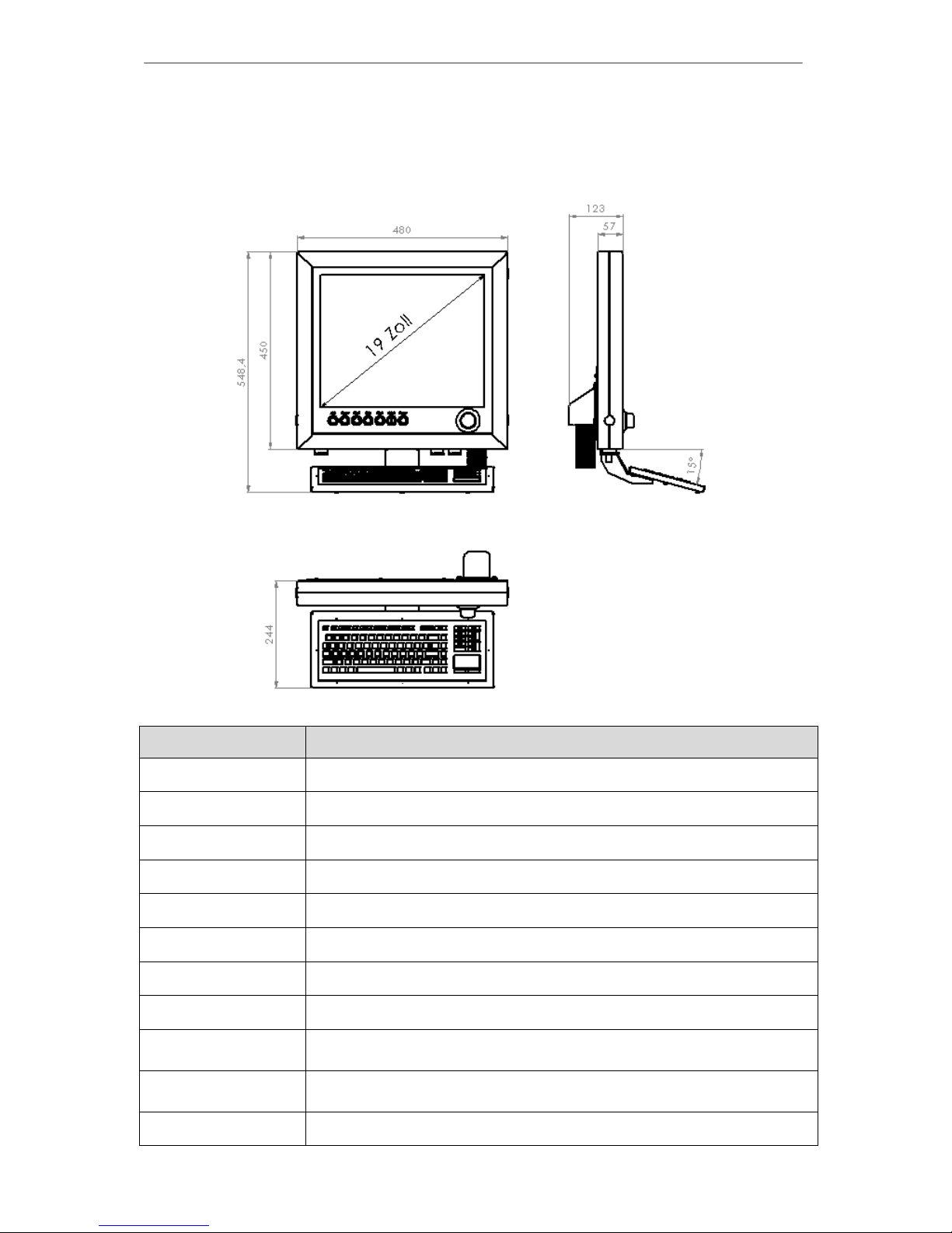
6 Technical specifications
Dimensions
6.1 Technical specifications of the iOP-19-TFT
Properties
Driver 19” TFT Active Matrix
Viewing angle 75°(horizontal) 60°(vertical)
Pixel size 0.264(H) x 0.264(W)
Viewing area 337 x 270 mm
max. pixel number 1280 x 1024
Colour 24-Bit colour depth 16.2 million
Connections 3 USB ports Pull-out USB 2.0 connection
Power supply: 12V DC, min. 60W, separate power unit required
Degree of protection
iOP-19-TFT IP 50
Keyboard IP 68
Ambient temperature
Storage temperature
5°C – 35°C
-25°C – 55°C
Weight approx. 15 kg

CNC control panel iOP-19-TFT
Page - 15
7 EC Declaration of Conformity
Der Hersteller
The manufacturer
isel Germany AG
Bürgermeister-Ebert-Str. 40
D-36124 Eichenzell
erklärt hiermit, dass folgendes Produkt
hereby declares that the following product
Geräteart: CNC-Bedienpanel iOP-19-TFT
Device: CNC-Control-Panel iOP- 19-TFT
Typ: iOP-19-TFT
Type:
Art.-Nr.: iOP-19-TFT: 371100 1000
Product - No.:
mit den Vorschriften folgender Europäischer Richtlinien übereinstimmt:
complies with the requirements of the European Directives:
EG-Richtlinie 2004/108/EG
EC-Directive 2004/108/EC
EMV Richtlinie
EMC directive
EG-Richtlinie 2006/95/EG
EC-Directive 2006/95/EC
Niederspannungsrichtlinie
low voltage directive
Folgende harmonisierte Normen wurden angewandt:
Following harmonized standards have been applied:
EN 61000-6-2:2006 EMV - Fachgrundnorm - Störfestigkeit für Industriebereich
EMC - Generic standards - Immunity for industrial environments
EN 61000-4-2:2008 EMV - Prüf- und Messverfahren - Prüfung der Störfestigkeit gegen Entladung
statischer Elektrizität (ESD)
EMC - Testing and measurement techniques; Electrostatic discharge immunity test
EN 61000-4-4:2012 EMV - Prüf- und Messverfahren - Prüfung der Störfestigkeit gegen schnelle
transiente elektrische Störgrößen (Burst)
EMC - Testing and measurement techniques - Electrical fast transient/burst immunity test
EN 61000-4-5:2007 EMV - Prüf- und Messverfahren - Prüfung der Störfestigkeit gegen energiereiche
Impulse (Surge)
EMC - Testing and measurement techniques - Surge immunity test
EN 61000-4-11:2005 EMV - Prüf- und Messverfahren - Prüfung der Störfestigkeit gegen Spannungs-
einbrüche / Spannungsunterbrechungen
EMC - Testing and measurement techniques - Voltage dips, short interruptions and voltage
variations immunity tests
EN 61000-6-4:2011 EMV - Fachgrundnorm - Störaussendung Industriebereich
EMC - Generic standards - Emission standard for industrial environments
DIN EN 55011:2011 Industrielle, wissenschaftliche und medizinische Hochfrequenzgeräte (ISM-Geräte) -
Funkstörungen - Grenzwerte und Messverfahren
Industrial scientific and medical (ISM) radio-frequency equipment - Electromagnetic
disturbance characteristics - Limits and methods of measurement
Dermbach, 17.06.2014
___________________________
Werner Kister, Vorstand / managing board
 Loading...