

Page 1

isel Germany AG, D-36124 Eichenzell, Bürgermeister-Ebert-Str. 40 (06659)981-0 (06659)981-776
CNC Servo Controller
iCU-DC
iCU-EC
Operating Instructions
Page 2
iCU-DC / iCU-EC Operating Instructions
The information, technical data and measurements in these printed materials conform
to the latest technological advances at the time of publication. However, the possibility
of printing errors and mistakes cannot be excluded. We would be grateful if you
suggest improvements or point out errors.
We note that the software and hardware brand names used in our printed materials
are generally subject to trademark, brand name or patent protection belonging to each
respective company.
All rights reserved. No part of our printed materials may be reproduced in any form
(print, photocopy or any other process) or processed, duplicated or disseminated via
electronic systems without written permission from isel Germany AG.
Manufacturer: isel Germany AG
Bürgermeister-Ebert-Straße 40
D-36124 Eichenzell
Tel.: +49 (0)6659 981-0
Fax: +49 (0)6659 981-776
Email: automation@isel.com
http://www.isel.com
Revisions
Date of
change
Reason for change
Changed by
b
04/07/2018
Page 15 changed, E/A ports
CB
a
05/01/2015
Serial number
RL 2014
First print
We reserve the right to make technical changes.
Current operating instructions and manuals can be downloaded at:
www.isel-data.de/manuals
Page 3

iCU-DC / iCU-EC Operating Instructions
Contents
1 Introduction .......................................................................................................... 4
1.1 Safety symbols ................................................................................................ 4
1.2 Safety information ............................................................................................ 5
2 Variants ................................................................................................................. 7
3 Technical data ...................................................................................................... 8
4 Hardware description ........................................................................................... 9
4.1 Front side ......................................................................................................... 9
4.2 Back side of iCU-DC / iCU-EC ........................................................................11
4.3 Structure of iCU-DC / iCU-EC .........................................................................18
5 Initialisation ........................................................................................................ 19
6 Software .............................................................................................................. 20
6.1 Installation of the initialisation software ...........................................................20
6.2 Installing ProNC / Remote and first steps .......................................................22
7 EC Declaration of Conformity ........................................................................... 26
8 List of sources .................................................................................................... 27
9 Index .................................................................................................................... 27
Page 4
iCU-DC / iCU-EC Operating Instructions
Page - 4
1 Introduction
The CAN Controllers of the iCU Series are compact, high-performance drive
controllers for 2 to 6 linear or rotational axles. The table housing integrates all control
components required for solving various automation tasks.
The table housing integrates all control components required for solving widely
varying automation tasks. These range from the output stage to the I/O component
group to safety controlling.
The control computer interface is a CANopen PCI card which serves as a CAN
master for the drive regulators and the I/O component group. External expansions
for up to 128 CAN nodes are also easily possible. The connections on the back side
of the control computer make it possible to easily connect a monitor, among other
things. USB sockets are available for attaching various peripheral equipment such as
mouse and keyboard. A LAN connection allows for integration into an existing
network and can also be used for remote maintenance.
The NC controller core makes it possible to interpolate up to 6 axles (linear, circular,
or helix), and online and Lock Ahead belt processing are also available. Using the
software ProNC, individual axles can be controlled as handling axles (besides the
interplating axles).
The iCU-DC CAN Controllers can drive up to 6 brushed DC servo motors. The
iMD10 output stages in use have automatic jerk limitation and standstill monitoring
(up to safety category 3).
Controllers in the iCU-EC Series can drive up to 6 brushless DC servo motors. The
iMD20 output stages in use have automatic jerk limitation and standstill monitoring
(up to safety category 3).
1.1 Safety symbols
Warning!
Warning of dangers which can lead to adverse effects on health, physical
injury, or death.
Warning! Life-threatening voltage
Warning of danger from electrical current. Non-compliance can result in
severe injury or death.
Attention!
This symbol is for notices, non-observance of which can lead to damage
or faults.
Information:
This symbol is for important information and notices.
Page 5

iCU-DC / iCU-EC Operating Instructions
Page - 5
1.2 Safety information
▪ The iCU-DC and iCU-EC CNC Controllers are constructed according
to current technological advances and recognised safety regulations.
▪ The machine must only be operated when it is in perfect technical
condition. Faults must be dealt with immediately. Children, and
anyone who has not been trained, are not permitted to operate the
machine.
▪ The machine must only be used according to its intended purpose.
Control of 2 to 6 linear or rotational axles with brushed DC servo
motors (iCU-DC) or brushless DC servo motors (iCU-EC) and
incremental measurement system (encoder).
▪ All work must only be done by authorised specialist personnel with
regard to the regulations of the electrical industry as well as accident
prevention regulations. Before opening the housing or doing any work
on the electrical installation, you must unplug the power cable.
▪ Assembly and use of equipment must be carried out according to the
norms of the Declaration of Conformity. The regulations and
threshold values observed by the manufacturer are not sufficient to
protect from improper use of the equipment.
▪ The device must not be exposed to high air humidity or high levels of
vibration.
▪ Keep this manual in a safe place and oblige each user to comply with
it!
▪ Failure to observe these operating instructions can cause property
damage, severe physical injuries, and death.
Page 6

iCU-DC / iCU-EC Operating Instructions
Page - 6
▪ Warning! High earth leakage current (ground discharge current,
protection conductor current). Before connecting to the AC supply
network, it is necessarily required an additional protective
grounding. Before connecting the CNC controller to the AC supply
network, an additional protective grounding (cross section: 2.5 mm2
or 4 mm2, see below) has to be connected! Before the electrical startop of the controllers a protective grounding of 2.5 mm2 (protected
installation) or a protective conductor of 4 mm2 (unprotected
installation) has to be connected durably to the marked clamping point
at the back of the housing where the cross section of the protective
grounding shall not be less than 10 mm2 copper or 16 mm2 aluminum
has (e.g. electrical distribution of the building). Please instruct an
electrician with these implementation. When using the Residual
Current circuit Device (RCD) for line fuses/fault current delimitation: Do
not use an RCD with AC characteristics. Using a frequency inverter
and choppered power stages in the power units may cause
superimposed AC fault units with pulsating direct current and direct
current apart from AC fault currents. Please consult your electrician.
▪ The term leakage is understood here as grounding discharge
current. This is defined in the standard EN 60204-1:2006 section
8.2.8, note 1
▪ If the CNC machine (ideal) is set up isolated from the reference
potential, the grounding discharge current is equal to the
protective grounding stream.
Page 7

iCU-DC / iCU-EC Operating Instructions
Page - 7
2 Variants
Type
Motor
Output
stages
max. Number of
axles
iCU-DC
BDC Servo motors (brushed)
iMD10
6
iCU-EC
BLDC Servo motors (brushless)
iMD20
6
Scope of delivery iCU-DC (Art.-No. 354002 10X10)
• iCU-DC servo controller as a tabletop device with the following components:
o max. 6 integrated iMD10 performance output stages for brushed DC
servo motors /1/
o Control computer iPC25 with CAN PCI card iCC10
o CAN IO 8/12-4/1 Module
o Safety circuit module iSM5
• Power cable 230VAC (Safety contact plug, IEC-60320 appliance connector
plug)
• RS232 communications cable for firmware updates, 9 pin sub-D (socket) to
RJ45 (plug)
• Accessories kit (appliance plug connector, strapping plug, etc.)
• Remote control software from Version 1.46.6.6 (optional: ProNC)
• Operating Instructions
• Optional: Frequency converter SKC750, SKC1500 for main spindle drive,
max. 4 axles possible
Scope of delivery iCU-EC (Art.-No. 354002 20X10)
• iCU-EC servo controller as a tabletop device with the following components:
o max. 6 integrated iMD20 performance output stages for brushless DC
servo motors /2/
o Control computer iPC25 with CAN PCI card iCC10
o CAN IO 8/12-4/1 Module
o Safety circuit module iSM5
• Power cable 230VAC (Safety contact plug, IEC-60320 appliance connector
plug)
• RS232 communications cable for firmware updates, 9 pole sub-D (socket) to
RJ45 (plug)
• Accessories kit (appliance plug connector, strapping plug, etc.)
• Remote control software from Version 1.46.6.6 (optional: ProNC)
• Operating Instructions
• Optional: Frequency converter SKC750, SKC1500 for main spindle drive,
max. 4 axles possible
1
X … Number of axles, 2-6
Page 8
iCU-DC / iCU-EC Operating Instructions
Page - 8
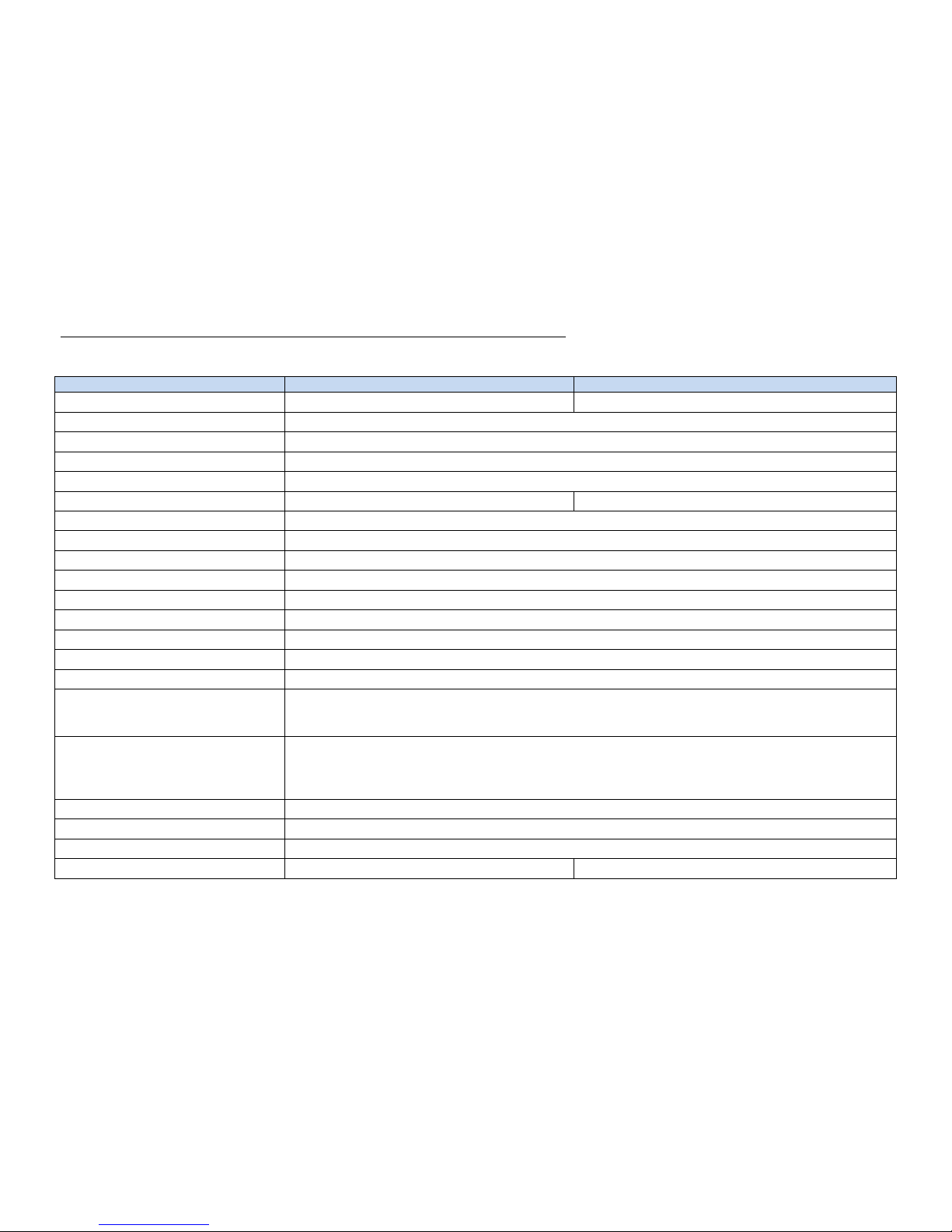
3 Technical data
Controller
iCU-DC
iCU-EC
Servo motor type
BDC Servo motors (DC brushed)
BLDC Servo motors (DC brushless, EC)
Max. Number of axles
6
Power input
115 - 230 VAC, 50 … 60 Hz
Fuses
2 x 6.3A (inert)
Power supply performance
1000 W
Performance output stage
iMD10
iMD20
Intermediate circuit voltage
48 VDC
Max. Nominal motor current
12 A
Max. Peak motor current
25 A
Descriptive code for safety data
EN ISO 13849-1:2006 Category 3, PL d
Protection type
IP20
Environment temperature
0°C to 50°C
Storage temperature
-20°C to +65°C
Air humidity
max. 90%, non-condensating
Safety functions
Can be integrated into higher-level emergency stop circuits, hood control, spindle control
I/O component group
4 digital inputs
8 digital outputs (4 relay outputs, 4 electrical outputs
1 x 115-230 V relay output (max. 6A)
Control computer
1.8 GHz processor
RAM ≥ 1 GB
Hard drive 2.5” SATA ≥ 120 GB
2 x USB 2.0 on the front
Operation
Function keys, emergency stop
Operating system
Windows Embedded standard 7 (64Bit)
Control software
Remote (Optional: ProNC, isyCAD/CAM)
Measurements, W x H x D
630 x 230 x 400
630 x 230 x 400
Page 9
iCU-DC / iCU-EC Operating Instructions
Page - 9
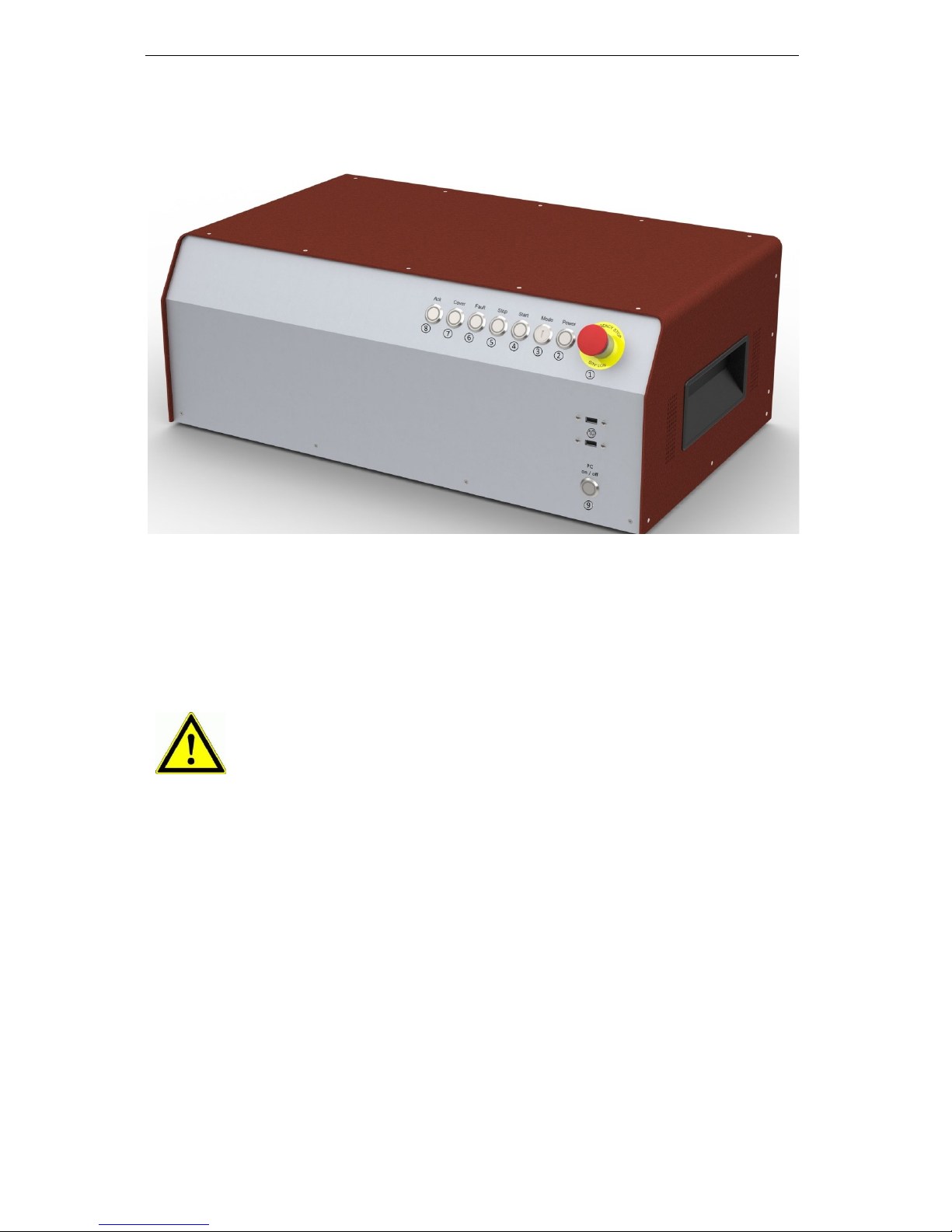
4 Hardware description
4.1 Front side
1 - Emergency stop switch
The emergency stop switch is for switching off the power supply to the stepping
motor output stage in case of danger.
By this we are referring to dangers which could affect the health of the operator or
the safety of the machine.
2 - Power button
Using the you can switch on the voltage supply to the output stages. The prerequirements for this are:
- The power source must be switched on using the backwards “on” switch.
- The emergency stop switch must be “pulled out”.
When the main voltage is successfully switchted on, this is signalled by the lighted
power button.
3 - Mode Selection Switch (Key switch)
This key switch selects Automatic or Setup mode.
When the emergency stop switch is activated, axle movement is
braked in a controlled manner and the main voltage is switched off
according to Stop Category 1 with a time delay (DIN EN 60204-1).
The 115/230VAC power supply is still connected to the machine.
Only the power supply to the output stage is switched off.
Page 10

iCU-DC / iCU-EC Operating Instructions
Page - 10
In automatic mode, you can only open the machine’s hood or
door when the axles are not moving and the connected milling
spindle is switched off.
In setup mode, you can only open the machine’s hood or door
when the working spindle is switched off. In this mode you can
also drive the axles with the hood open, if you press the
Acknowledge button “ACK” to do so.
Ensure that only trained personnel
are allowed operate the machine when
it is in setup mode (key switch set to TEST)!
4 - Start button
Pressing the Start button will open either the user program (ISO, PAL or NCP file)
within the operating interface ProNC, or the user application (ISO, NCP or CNC file)
within the remote control program.
If no user program is open when you press the Start button, ProNC or
Remote will request you to select a user program.
5 - Stop button
Pressing the interrupts a running user program / axle movement. You can then
resume the user program / axle movement by pressing the Start button.
6 - Cover button
This button is used to open the hood (if there is one). The hood can only be opened
when the conditions are fulfilled as described under “Mode Selection Switch”. The
button will light up in white when the hood is released for opening.
7 - Fault signal
The fault signal shows that there is a fault in the safety circuit.
8 - ACK (ACKnowledge button)
You must press this button in order to move the axles in setup mode with the hood
open.
9 - PC Start button
Press this button to switch on the integrated control computer.
10 - USB 2.0 connections
USB devices (data sticks, external CD/DVD drives) can be connected to these
sockects.
Page 11

iCU-DC / iCU-EC Operating Instructions
Page - 11
4.2 Back side of iCU-DC / iCU-EC
➀ Connections for motor and encoder signal cables
iCU-DC - Motor, Encoder and Signal Cables
Motor connection (X, Y, Z, A, B, C), 8+1 pole M23 socket
Pin
Signal
Wire number
Name
1 1 1
Motor phase 1*
2 2 2
Motor phase 2*
3 1 3
Motor phase 1*
4 2 4
Motor phase 2*
5
Brake
brown
Motor brake
6
Brake_GND
white
Motor brake GND
7
--- 8 --- 9 PE
yellow / green
grounding conductor
* Each motor phase is connected via two wires.
Encoder/ Signal connection, 15 pole Sub-D socket
Pin
Signal
Cable wire colour
Name
1
n/a 2 VCC_Encoder
red
Digital +5V DC
3
/ENC_Z
orange / black
Encoder track /Z
4
/ENC_B
brown / black
Encoder track /B
5
/ENC_A
Grey / black
Encoder track /A
6
VCC_Logic
Logic +24V DC
7
LIMIT_SW1
End position switch 1
8
GND_24V
Logic GND
9
n/a
10
D_GND
black
Digital GND
11
ENC_Z
orange
Encoder track Z
12
ENC_B
brown
Encoder track B
13
ENC_A
grey
Encoder track A
14
REF_SW
green
Reference switch
15
LIMIT_SW2
End position switch 2
iCU-DC - Motor, Encoder and Signal Cables
Page 12

iCU-DC / iCU-EC Operating Instructions
Page - 12
Motor connection (X, Y, Z, A, B, C), 8+1 pole M23 socket
Pin
Signal
Cable wire colour
Name
1 U black 1
Motor phase U
2 V black 2
Motor phase V
3 W black 3
Motor phase W
4
--- 5 Brake
brown
Motor brake
6
Brake_GND
white
Motor brake GND
7
--- 8 --- 9 PE
yellow / green
grounding conductor
Encoder/ Signal connection, 15 pole Sub-D socket
Pin
Signal
Cable wire colour
Name
1
HALL_A _IN
yellow
Hall Signal A
2
VCC_Encoder
red
Digital +5V DC
3
/ENC_Z
orange / black
Encoder track /Z
4
/ENC_B
brown / black
Encoder track /B
5
/ENC_A
Grey / black
Encoder track /A
6
VCC_Logic
Logic +24V DC
7
LIMIT_SW1
End position switch 1
8
GND_24V
Logic GND
9
HALL_B_IN
white
Hall Signal B
10
D_GND
black
Digital GND
11
ENC_Z
orange
Encoder track Z
12
ENC_B
brown
Encoder track B
13
ENC_A
grey
Encoder track A
14
HALL_C_IN
green
Hall Signal C
15
LIMIT_SW2
End position switch 2
Page 13

iCU-DC / iCU-EC Operating Instructions
Page - 13
➁ Manual operating console - 25 pole Sub-D (optional model)
This connection is only used for controllers that do not have the integrated function
keys in the front of the housing.
This connects the operating elements (buttons, switches) of:
- an external manual operating console
- an Isel CNC operating panel
with the appropriate socket on the safety circuit module of the controller inside the
controller housing.
Pin
Signal
Name
1
EMERGENCY
STOP_1
Emergency Stop channel 1, connection 1.1
2
EMERGENCY
STOP_1
Emergency Stop channel 1, connection 1.2
3
EMERGENCY
STOP_2
Emergency Stop channel 2, connection 2.1
4
EMERGENCY
STOP_2
Emergency Stop channel 2, connection 2.2
5
24V
+24 V DC
6
POWER BTN
Power button input
7
POWER LAMP
Power light output
8
24V
+24VDC
9
KEY SWITCH Test
Key switch test mode input
10
KEY SWITCH Auto
Key switch automatic mode input
11
24V
+24VDC
12
ACK_1
Acknowledge button channel 1 input
13
24V
+24VDC
14
ACK_2
Acknowledge button channel 2 input
15
COVER SWITCH
Cover button input
16
COVER SWITCH
Cover button output
17
GND
18
19
20
FAULT LAMP
Fault light output for operating console
21
START BTN
Start button input (normally open contact)
22
STOP BTN
Stop button input (normally closed contact)
23
START LAMP
Start llight output
24
STOP LAMP
Stop light output
25
n/a
The length of the connection cable for the manual operating console /
CNC operating panel is max. 5m.
Page 14

iCU-DC / iCU-EC Operating Instructions
Page - 14
➂ Additional operating console - 15 pole Sub-D (optional model)
We use this connection when an additional Isel operating console is connected.
Pin
Signal
Name
1
EMERGENCY
STOP_1
Emergency Stop channel 1, connection 1.1
2
EMERGENCY
STOP_1
Emergency Stop channel 1, connection 1.2
3
EMERGENCY
STOP_2
Emergency Stop channel 2, connection 2.1
4
EMERGENCY
STOP_2
Emergency Stop channel 2, connection 2.2
5
GND
GND operating console
6
LAMP ACK
ACK light switch output
7
24V
+24VDC
8
ACK_1
Acknowledge button channel 1 input
9
24V
+24VDC
10
ACK_2
Acknowledge button channel 2 input
11
COVER SWITCH 1
Cover button input 1
12
COVER SWITCH 1
Cover button output 1
13
COVER SWITCH 2
Cover button input 2 (optional)
14
COVER SWITCH 2
Cover button output 2 (optional)
15
n/a
The length of the connection cable for the additional operating console is
max. 5m.
➃ Cover - Sub-D 9 pole socket
At this connection, you can integrate the of the attached machine into the controller’s
safety circuit.
Pin
Name
1
+Coil, normally closed contact
2
Switch 1, 1.1
3
Switch 1, 1.2
4
Switch 2, 2.1
5
Switch 2, 2.2
6
-Coil, normally closed contact
7, 8, 9
not used
Page 15

iCU-DC / iCU-EC Operating Instructions
Page - 15
➄Digital Inputs - 8 pole, left to right E1.1 – E1.4
The installed I/O component group has one digital input port. The inputs E1.5 - E1.8)
are already partially wired internally and occupied by signal inputs and not usable by
the user. The digital inputs E1.1 - E1.4 may be assigned by the user.
Properties
- Optoelectronic coupler inputs
- Input current approx. 8mA
Wiring
Pin
Input
Name
1
In 1
Input E1.1
2
VCC
+24VDC
3
In 2
Input E1.2
4
VCC
+24VDC
5
In 3
Input E1.3
6
VCC
+24VDC
7
In 4
Input E1.4
8
VCC
+24VDC
Note the default assignment of the first input port (E1.5 - E1.8) when
setting the “signalling” in the user interface Remote / ProNC.These inputs
are already wired inside the controller to their modules and can no longer
be used by the operator!
➅ Remote- Safety circuit interface, 8 pole, left to right
Using this interface, you can integrate the emergency stop circuit of the equipment
output unit into a higher-level safety circuit system. Here you can also tap the analog
output signal 0...10V of the integrated I/O module.
Pin
Signal
Name
1
EMERGENCY
STOP_1
External emergency stop channel 1, connection 1.1
2
EMERGENCY
STOP_1
External emergency stop channel 1, connection 1.2
3
EMERGENCY
STOP_2
External emergency stop channel 2, connection 2.1
4
EMERGENCY
STOP_2
External emergency stop channel 2, connection 2.2
5
ANA_GND
Analog GND
6
ANA_0_10V
Analog 0…10V DC
7
----
8
----
Page 16

iCU-DC / iCU-EC Operating Instructions
Page - 16
➆ Digital electrical outputs - 8 pole, left to right A1.1 – A1.4
The installed I/O component group has two digital output ports, each with eight
digital switching outputs. The first output port (A1.1 - A1.8) is already partially wired
internally and occupied by switching outputs. The outputs A1.1 - A1.4 may be
assigned by the user.
Properties
- 4 x digital electronic outputs
- Imax < 350mA, 24VDC
- Thermal protection
- Short-circuit protection
Wiring
Pin
Output
Name
1
Out1
Output A1.1
2
GND
GND
3
Out2
Output A1.2
4
GND
GND 5 Out3
Output A1.3
6
GND
GND 7 Out4
Output A1.4
8
GND
GND
Note the default assignment of the first output port (A1.1 - A1.8) when
setting the “signalling” in the user interface Remote / ProNC. The outputs
A1.5 - A1.8 are already wired inside the controller to their modules and
can no longer be used by the operator!
When using intuctance, an free-wheeling diode is necessarily.
➇ Digital Relay Outputs - 8 pole, left to right A2.1 – A2.4
The installed I/O component group has a second digital output port, with four more
digital relay switching outputs. The second output port (A2.1 - A2.8) is already
partially wired internally and occupied by switching outputs. The outputs A2.1 - A2.4
may be assigned by the user.
Properties
- 4 x digital relay outputs
- Imax < 5 A, 24VDC
- Thermal protection
- Short-circuit protection
Wiring
Pin
Output
Name
1
Out1
Output A2.1
2
GND
GND 3 Out2
Output A2.2
4
GND
GND
5
Out3
Output A2.3
6
GND
GND 7 Out4
Output A2.4
8
GND
GND
Page 17

iCU-DC / iCU-EC Operating Instructions
Page - 17
➈AC Input – 115/230 VAC, 50 …60 Hz
The power input module includes these components: appliance connector socket,
filter, fuse holder, fuses and power switch. The supplied power cable must be
connected with the appliance connector socket and the power socket before
initialisation. After that, the controller can be switched on using the main switch.
! Neutral Conductor Fuse !
➉Spindle -115V/ 230V connection
Here at this output, you can directly connect a milling spindle without RPM control if
you use the supplied mating plug. Maximum switching at the relay output is
115V/230VAC / 6A. The signal for the spindle to start (output +24V) is switched via
the CAN I/O module, analysed via the SK module (iSM5), and then the power supply
of 115/230V is switched to the working spindle (e.g. UFM 500, 750, 1050) via a
relay.
Take note of the CAN I/O module table defining assigned spindle start
signals, in section 4.2.
⑪ Connection for main spindle drive (optional)
Here at this connection, a processing spindle with RPM control is attached
(asynchronous motor). The (optional) frequency converter is located in the controller
and is operated via the safety circuit and I/O module.
Pin
Name
1
Motor phase U
4
Motor phase V
3
Motor phase W
PE
PE
A
-
B - C
Fan 230V AC-L
D
Fan 230V AC-N
Housing
⑫ Ethernet connection for the integrated control computer, IPC15
1x RJ45 socket for network integration (100MBit, LAN, Ethernet)
⑫ VGA connection for the integrated control computer, IPC15
15 pole connection socket for a VGA monitor
⑭ USB 2.0 connections
USB devices (data sticks, external CD/DVD drives) can be connected to these
sockects.
Page 18

iCU-DC / iCU-EC Operating Instructions
Page - 18
4.3 Structure of iCU-DC / iCU-EC
iSM 5 Safety circuit module
iPC25 control computer
with integrated CAN PCI
Function keys module
for operating elements
(buttons, switches) on the
front side of the controller
iMD10 / iMD20 output
stages for brushed DC
servo motors /
brushless DC servo
motors
Powerpack
115/230VAC,
24V DC 100W for
Logic
Powerpack 115/230VAC,
12V DC 60W for PC
Powerpack 115/230VAC,
48V DC 1000W for motors
CAN I/O-16/16
I/O module
Frequency converter
SKC (optional)
Page 19

iCU-DC / iCU-EC Operating Instructions
Page - 19
5 Initialisation
Preparation
Before you first start up the controller, please check the scope of delivery. The
following parts should be included:
- Power cable
- Operating Instructions
If all these are present, then you can begin with commi.
If the environmental temperature is less than 0°C, you should leave
the controller at room temperature for at least two hours before use,
to prevent damage to the electronic components.
To do this, first make all the necessary connections:
- Connect the power cable
- Connect the motor and encoder cables from the axles (motors) to the back of
the controller
- Check that all the other cables are correctly attached to the controller
Initialisation
- Use the power switch (on the back) to turn on the controller.
- Turn on the control computer using the green button on the back, this button
should now light up in green the computer will now boot up the installed
operating system
- Installing the control software (if not already installed)
▪ Remote or ProNC (1) (from Version 1.46.6.6)
- Installing the initialisation software (if not already installed)
▪ DCSetup (2)
▪ ACSetup (3)
- Check that the emergency stop switch is pulled out
- Press the power button - The power supply to the output stages
should now be activated
- Parameterisation of the performance output stages using the program
DCSetup.exe / ACSetup.exe
- Setting up the system’s axle kinematics using CANSet.exe
- Operating the controller and the connected axles using the ProNC or Remote
operating and programming interface
Page 20

iCU-DC / iCU-EC Operating Instructions
Page - 20
6 Software
6.1 Installation of the initialisation software
Initialisation / parameterisation of the motor output stages integrated in the
controller’s iCU-DC / iCU-EC is done using the initialisation programs
DCSetup.exe (2)
for:
brushed DC servo motors with motor output stage iMD10
or
ACSetup.exe (3)
for:
brushless DC servo motors with motor output stage iMD20 and
Please proceed as follows to install the initialisation programs after the fact:
1. Connect the ProNC/Remote installation medium (supplied CD or USB stick) to
the control computer.
2. The following auto-start window will appear (when installing from CD).
If the auto-start window does not appear, please open Windows Explorer
and open the main directory of the installation medium. Double-click on
the file “Autorun.exe”.
Page 21

iCU-DC / iCU-EC Operating Instructions
Page - 21
3. Click on the option “Install control software” and then the following window will
appear on the screen:
Now choose the appropriate initialisation software for your motor type and click
on the option (e.g. “ACSetup installation“) to begin the installation.
Follow the instructions in the installation wizard.
After installation is complete, click on “Finish” to close the auto-start menu.
Start the initialisation program DCSetup.exe / ACSetup.exe either via the
shortcut on the Windows Desktop or via the start menu item:
Start Programs ACSetup DCSetup / ACSetup
You can find information about the parameterisation of the iMD10
performance output stage in the handbook /1/ DC servo positioning
module with CanOpen Interface UVE 8112 / iMD10. Open the file
“dcsetup_ger.pdf” using the start menu option.
You can find information about the parameterisation of the iMD20 and
iMD40 performance output stages in the handbook /2/ AC servo
positioning module with CanOpen Interface iMD20 / iMD40. Open the
file “acsetup_ger.pdf” using the start menu option.
Page 22

iCU-DC / iCU-EC Operating Instructions
Page - 22
6.2 Installing ProNC / Remote and first steps
The iCU-DC / iCU-EC controller is operated either via the control software, Remote,
or the programming software, ProNC.
If the factory has not installed any software yet, please proceed as follows to install
the programs after the fact:
1. Connect the ProNC/Remote installation medium (supplied CD or USB stick) to
the control computer.
2. The following auto-start window will appear (when installing from CD).
If the auto-start window does not appear, please open Windows
Explorer and open the main directory of the installation medium.
Double-click on the file “Autorun.exe”.
Page 23

iCU-DC / iCU-EC Operating Instructions
Page - 23
3. Click on the option “ProNC installation“
Follow the instructions in the installation wizard.
In the “Control Selection” window, select the item “CAN Bus Control” to install the
CAN bus software module.
After installation is complete, click on “Finish” to close the auto-start menu.
4. Use the configuration program CANSet.exe (shortcut on the Windows Desktop or
via the start menu option: Start Programs isel CAN CNC Control
CANSet), to set up machine-specific parameters (CAN interface, axles used, axle
type, etc.).
Page 24

iCU-DC / iCU-EC Operating Instructions
Page - 24
Save your configuration in an (*.ini file). You must then later use this file in the
ProNC/Remote operating interface as the motion control module DLL initialisation
file.
5. Start the user interface ProNC.exe either via
the shortcut on the Windows Desktop or via the start menu option:
Start Programs CNC workbench ProNC
Page 25

iCU-DC / iCU-EC Operating Instructions
Page - 25
In the Settings menu (MenuSettingsControl) for Motion Control Module
Axle system 1, select the initialisation file that you saved before. Click on the
button “Save & Initialise” to save the settings and put the controls into their start
settings.
6. Carry out a “Software Reset” and a “Reference Movement” to check the correct
function of the machine and the system.
For further information on configuring the ProNC / Remote, please refer to
the programs’ online help sections (Help menu or F1 key).
Page 26

iCU-DC / iCU-EC Operating Instructions
Page - 26
7 EC Declaration of Conformity
The manufacturer
isel Germany AG
Bürgermeister-Ebert-Str. 40
D-36124 Eichenzell
hereby declares that the following product
Device: CAN-Servo-Controller
Type: iCU-DC / iCU-EC
Product No.: iCU-DC: 354002 10X0
iCU-EC: 354002 20X0
Serial no.: ___________
complies with the requirements of the European Directives:
EC-Directive 2004/108/EC
EMC directive
EC-Directive 2006/95/EC
low voltage directive
Following harmonized standards have been applied:
EN 61000-6-2:2006
EMV - Fachgrundnorm - Störfestigkeit für Industriebereich
EMC - Generic standards - Immunity for industrial environments
EN 61000-4-2:2008
EMV - Prüf- und Messverfahren - Prüfung der Störfestigkeit gegen Entladung
statischer Elektrizität (ESD)
EMC - Testing and measurement techniques; Electrostatic discharge immunity test
EN 61000-4-4:2012
EMV - Prüf- und Messverfahren - Prüfung der Störfestigkeit gegen schnelle
transiente elektrische Störgrößen (Burst)
EMC - Testing and measurement techniques - Electrical fast transient/burst immunity test
EN 61000-4-5:2007
EMV - Prüf- und Messverfahren - Prüfung der Störfestigkeit gegen
energiereiche Impulse (Surge)
EMC - Testing and measurement techniques - Surge immunity test
EN 61000-4-11:2005
EMV - Prüf- und Messverfahren - Prüfung der Störfestigkeit gegen
Spannungs-einbrüche / Spannungsunterbrechungen
EMC - Testing and measurement techniques - Voltage dips, short interruptions and voltage
variations immunity tests
EN 61000-6-4:2011
EMV - Fachgrundnorm - Störaussendung Industriebereich
EMC - Generic standards - Emission standard for industrial environments
DIN EN 55011:2011
Industrielle, wissenschaftliche und medizinische Hochfrequenzgeräte (ISMGeräte) - Funkstörungen - Grenzwerte und Messverfahren
Industrial scientific and medical (ISM) radio-frequency equipment - Electromagnetic
disturbance characteristics - Limits and methods of measurement
EN 60204-1:2006
Sicherheit von Maschinen – Elektrische Ausrüstung von Maschinen –
Teil 1: Allgemeine Anforderungen
Safety of machinery – Electrical equipment of machines – Part 1: General requirements
Dermbach, 16.07.2014
Werner Kister, Vorstand / managing board
Werner Kister, Chairman
Page 27

iCU-DC / iCU-EC Operating Instructions
Page - 27
8 List of sources
/1/ isel Germany AG.
Positioning module with CanOpen Interface UVE8112 / iMD10. 03/2008.
/2/ isel Germany AG.
Positioning module with CanOpen Interface iMD20 / iMD40. 03/2009.
/3/ isel Germany AG.
ProNC Operating Instructions. 2003.
/4/ isel Germany AG.
iPC25 Operating Instructions. 07/2014
Operating instructions and manuals can be downloaded at:
www.isel-data.de/manuals
9 Index
A
ACK 10
ACSetup 19
B
BLDC Servo motors 7
C
CANSet.exe 19
Cover button 10
D
door lock 14
E
emergency stop switch 9
Encoder 11, 12
I
iMD20 8
initialisation file 24
initialisation software 20
Installation 20
M
Mode Selection Switch 9
Motor connection 11, 12
P
power button 9
Power input module 17
ProNC 19
R
Remote 19
S
Software 20
Start button 10
Stop button 10
 Loading...