


Document 383025 xxxx MD 01204
Wiring and Operation Manual
4-axes step motor controller
CSD 405-IMC
®
--Compact powerful unit to drive up to four 2-phase step motors
CNC / DNC operation through internal microcontroller, flash data memory
- Interpolation modes: linear and circular, helix-interpolation optional
- Motor output 30V/2A per motor, step resolution 1600 steps/revolution
- 300VA power supply with emergency stop circuit according to EN 60204, emergency
stop switching element, Power button, cover switch-output
- 2 freely usable signal inputs (+24V active)
- 2 freely usable switching outputs (relay, +24 switching, 50mA)
- 2 AC outputs (1 relay output 5A, 1 solid-state relay 1.25A)
- Motor connection on the rear via 9-pin Sub-D socket plug
- Dimensions: w x h x d - 274 x 152 x 300mm
- Programmable through the software products: PAL-PC, PAL-PC 2.0 (Windows), ProNC
systro GmbH
Sachsenweg 8 D-36132 Eiterfeld
Tel.: (0 66 72) 898 620 E-Mail: sales@systro.de
l
l
l
l
www.systro.de
l
systro GmbH - a member of isel group
systro
Electronics for systems
7 8
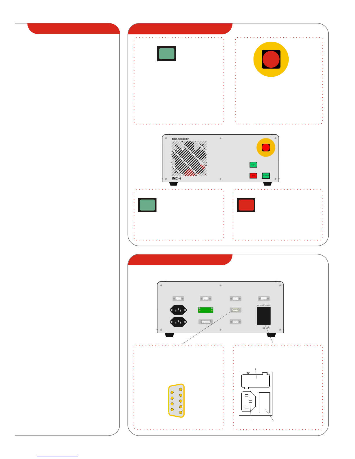
Front CSD 405-IMC
Safety information
l
l
l
l
l
l
l
l
l
l
l
The 4-axes step motor controller may
only be used to drive 2-phase step
motors of up to 60VA. Any other
utilization or a utilization exceeding
this specification is considered to be
non-conformant.
The controllers are designed
according to the state of the art and
the acknowledged safety-relevant
regulations.
The resources may only be operated
when they are in a perfect technical
condition. Malfunctions must be
removed immediately. Children and
persons who have not been
instructed are not permitted to
commission the unit.
All work is to be carried out only by
skilled personnel and in
consideration of the regulations of
the electronics industry and the
regulations for prevention of
accidents. Connection and assembly
work may only be carried out when
the device has been disconnected
from the mains.
Do not operate the controller without
connection to ground.
Before opening the unit, disconnect
the unit from the mains and pull off
the mains plug. Not all parts alive are
covered.
Installation and operation of the
resources must be performed
according to the standards of the
Declaration of Conformity. The
regulations and limiting values that
have been observed by the
manufacturer are not a protection if
the resources are used improperly.
Ambient temperature 0 to +40°C
storage temperature 10 to +70°C
Do not expose the unit to high
humidity, strong vibrations or
explosive gasses.
A low impedance potential
equalization of the machine and
control system are required to
comply with the EMC limiting values.
Keep these operating instructions
carefully and take care that every
operator adheres to the instructions.
Inobservance of the operating
instructions may result in damage to
property, serious personal injury and
death.
.
Emergency Stop
POWER-button
POWER
Rear CSD 405-IMC
Power switch, 2-line
Miniature fuse 2.5 A tr.
(miniature fuse 5x20mm,
IEC 127-2)
Power supply
connector
230V
Note:
The supply voltage
of the controller can be
coded internally to
AC 120V
Pressing this button activates the lock of
the integrated power relay and switches
on the voltage supply of the step motor
power output stage.
In the operation mode “POWER ON” the
POWER lamp lights up.
Operating the emergency stop
pushbutton off the voltage supply to the
output stage.
To unlock the switch pull the button out
of its lock-in position.
START
Initiates the program
sequence of the controller
after a stop command.
Pressing the Start button in
the storage mode starts the
stored program sequence.
Interrupts the program
sequence of the controller
and hence the step output to
the step motors.
7 8
STOP
systro GmbH
Sachsenweg 8 D-36132 Eiterfeld
Tel.: (0 66 72) 898 620 E-Mail: sales@systro.de
l
l
l
l
www.systro.de
l
RS 232
( )9-pin Sub-D pin plug
The serial interface is used to program
the controller.
5
1
9
6
--
--
--
--
Gnd
RxD
TxD
--
--
RS 232

Rear view
- switched AC 230V output.
The output is protected on the
internal control assembly by a
time-lag fuse 5A (HBD, 5x20mm).
AC Output X5
- switched AC 230V output.
The output is protected on the
internal control assembly by a
time-lag fuse 1.25A (HBD)
AC Output X6
(solid-state-relay)
Motor output X1 X4
9-pin Sub-D socket plug()
1
5
6
9
Reference switch
GND (Brake) **
Limit +
+24V (Brake) **
+24V/50mA
Motor phase 1A
Motor phase 1B
Motor phase 2A
Motor phase 2B
Output 2
+24V/0,25A
Output 1
+24V/0,25A
+24V
Input 2 (+18V ... +30V/10mA)
Input 1 (+18V ... +30V/10mA)
+24V
GND
GND
Power button (13)
Emergency stop (11)
Operating mode (23)
Operating mode (24)
Emergency stop (12)
Operating mode (23)
Power button (23)
Emergency stop (21)
Power button (14)
COVER button (13, a)
COVER button (14, b)
Not occupied
Operating mode (24)
Power button (24)
Emergency stop (22)
1
8
9
1
5
Emergency-Stop - switches off the supply
voltage to the power output stage.
12
22
11
21
(5)
(15)
(2)
(8)
Power-button - switches on the supply
voltage to the power output stages,
if there is no Emergency Stop
situation.
14
24
13
23
(9)
(14)
(1)
(7)
Operating mode- switches from automatic
to test operation
14
24
13
23
(4)
(13)
(3)
(6)
Cover button - unlocks the optional cover
switch with tumbler
14
b
13
a
(11)(10)
SK control
(15-pin Sub-D socket plug)
E1
A2
A1
E2
E3
A3 E4 A4
bipolar-serial bipolar-parallel
Example: 2-phase step motor (8-conductors)
(4)
(3)
(2) (1)
(4)
(3)
(2) (1)
(9)
(7)
(5)
Reference switch
Limit +
systro GmbH
Sachsenweg 8 D-36132 Eiterfeld
Tel.: (0 66 72) 898 620 E-Mail: sales@systro.de
l
l
l
l
www.systro.de
l
--
--
--
Cover unlock A2
Contact 11
Contact 12
Contact 21
Contact 22
Cover unlock A1
1
5
6
9
Safety interlocks (cover switch) together
with special operating and evaluation
units comply with the control category
3 or 4.
Cover switch X6
(9-pin Sub-D socket plug)
(2)
(3)
21
(4)
(5)
A1
A2
(1)(6)
22
11
12
AC (Out) AC (Out)
Protective conductor
AC (Out) AC (Out)
Protective conductor
E1
A2
A1
E2
E3
A3 E4 A4
User I/O
(Phönix, MC 3,81, 8pol.)
X5
X6
Z-Axis X-Axis
4.Axis Y-Axis
User I/O
Locking
Safety-Switch
X1 X2
X3 X4
RS 232
(Relay switched)
(12)
** after seiral number 178529
Output 2
+24V /200mA
Output 1
+24V /200mA
( max. 20mA) +24Vout
(+18V.. +30V/ 10mA) Input 2
(max. 20mA) +24Vout
GND
GND
(+18V.. +30V/ 10mA) Input 1
** only at motor output of z-axis (X1),
after serial number 178529

EC Declaration of Conformity
according to Article 8 of the „Machine Guideline“
(EC Directive 98/37/EC)
Document: K383025/03
We, the company
systro GmbH
Sachsenweg 8
D- 36132 Eiterfeld, Germany
declare that the certification process of the product
4-axes-step motor controller CSD 405-IMC
Part number: 383025 1000
has been carried out according to the EC Directives
- Low voltage directive
73/23/EWG (19.02.73), amendment 93/86/EWG (22.07.93)
- EMV Directive
89/336/EWG (03.05.89), amendment 91/263/EWG (29.04.91),
Amendment 2/31/EWG (28.04.92)
Amendment 93/68/EWG (22.07.93)
Eiterfeld, August 16, 2003
Rainer Giebel, General Manager
systro
Electronics for systems
systro
Electronics for systems
®
systro GmbH
Sachsenweg 8 D-36132 Eiterfeld
Tel.: (0 66 72) 898 620 e-Mail: sales@systro.de
l
l
l
l
systro GmbH - ein isel-Partner
 Loading...