

Iseki TJ75 Operation Manual
TJ75
MODEL:
I S E K I T R A C T O R S

ISEKI TRACTORS
1
TO OUR CUSTOMER
Thank you very much for purchasing an ISEKI tractor.
This operator's manual provides the information necessary for operating and maintaining
your tractor safely and properly. The contents are mainly composed of the following two
items:
Safety instructions: Essential items which you should observe while
operating the tractor
Technical instructions: Essential items which you should observe while
operating the tractor
Before starting to operate the machine for the first time, you should read this operation
manual thoroughly and carefully until you are sufficiently familiar with the operation of the
machine to do jobs safely and properly. The manual should be kept in a handy place so
you can refer to it when required. You are advised to refer to it from time to time to refresh
your understanding of the machine.
Your dealer has performed the pre-delivery service on your new machine.
He will discuss with you the operating and maintenance instructions gives in this manual,
and instruct you in the proper and varied applications of this machine. Call on him at any
time when you have a question, or need equipment related do the use of your machine.
Paragraphs in the manual and labels on the machine which are
accompanied by a caution particularly important information about
safe operation to avoid accidents. You should always keep precautions
in mind and follow them during operation.
Be sure to wear
personnel protective equipment
during operation
In some of the illustrations used in this operation manual, panels or
guards may have been remove for clarify. Never operate the tractor
with these panels and guards removed.
If the removal of a shield is necessary to make a repair, it must be
replaced before operation
All information, illustrations, and specifications contained in this manual are based on
the latest information available at the time of publication. The right is reserved to make
changes at any time without notice.

TJ75
2
TABLE OF CONTENTS
Light Turn Switch ........................................... 27
High - Low Beam Switch................................ 27
Power Take-Off (PTO) Switch ........................ 28
MAIN CLUTCH PEDAL ...................................... 29
BRAKES.............................................................. 29
Brake Pedals & Parking Brakes..................... 29
Parking Brake lever ....................................... 29
ENGINE SPEED CONTROLS ............................ 30
TRANSMISSION SHIFT LEVER AND BUTTON 30
Range Shift Lever and Gear Shift Button ...... 31
DIFFERENTIAL LOCK PEDAL ........................... 32
FOUR-WHEEL DRIVE SHIFT LEVER ................ 32
REAR PTO SELECTOR LEVER ......................... 33
THREE-POINT HITCH ........................................ 34
Control Lever ................................................. 34
Lowering Rate Control Knob.......................... 34
COMFORT ADJUSTMENTS ............................... 35
Steering Column Tilt ...................................... 35
Tool Box ......................................................... 35
5. OPERATION ........................................................ 36
BREAK-IN PERIOD ............................................ 36
STARTING .......................................................... 36
Pre-Start Inspection ....................................... 36
Normal Starting .............................................. 37
Restarting Warm Engine ................................ 38
Cold Weather Starting ................................... 38
Warm Up Period ............................................ 38
Operator Observations .................................. 39
Starting Circuit Operation .............................. 39
GROUND SPEED SELECTION .......................... 40
STOPPING TRACTOR ....................................... 42
DIFFERENTIAL LOCK ........................................ 43
FOUR-WHEEL DRIVE ........................................ 43
POWER TAKE-OFF (PTO) ................................. 44
Rear PTO Shaft ............................................. 44
PTO Operating Control .................................. 45
PTO Operating Controls ................................ 46
THREE-POINT HITCH ........................................ 47
Hitch Controls ................................................ 47
External Lift Arm UP / DOWN Switch ............ 47
Rear Linkage ................................................. 48
Attaching Implements .................................... 50
Using Position Control ................................... 51
Using Draft Control (accessory)..................... 52
Detaching Implements ................................... 53
EXTERNAL AUXILIARY HYDRAULICS .............. 54
DRAWBAR .......................................................... 55
6. INSTRUMENTS & CONTROLS & OPERATION . 56
OPENING/CLOSING DOORS ............................ 57
TO OUR CUSTMER ................................................. 1
TABLE OF CONTENTS ........................................... 2
1. SAFETY ............................................................... 5
PERSONAL SAFETY INSTRUCTIONS .............. 5
MAKING YOUR TRACTOR A SAFE
VEHICLE ............................................................. 5
HOW TO MAINTAIN SAFETY ....................... 5
HOW TO BE A SAFE OPERATOR ................ 6
WHEN ANOTHER PERSON OPERATES
YOUR MACHINE ........................................... 6
BEFORE OPERATION .................................. 7
STARTING ENGINE AND MOVING
TRACTOR ..................................................... 7
WHEN TRAVELLING ..................................... 8
LOADING ONTO OR UNLOADING FROM A
TRUCK .......................................................... 9
SPECIFICATIONS OF THE RAMPS ............. 10
DURING OPERATION ................................... 10
INSPECTION AND MAINTENANCE ............. 11
STORAGE ..................................................... 12
MAINTENANCE OF THE ELECTRIC
SYSTEM ............................................................. 13
TO MAINTENACE ELECTRIC WIRING ........ 13
TO HANDLE THE BATTERY ......................... 13
TO HANDLE BOOSTER CABLES ................ 14
SAFETY DECALS ......................................... 14
SAFETY DECALS AND THEIR
LOCATIONS .................................................. 15
LOCATION OF SAFETY DECALS ................ 18
2. INTRODUCTION .................................................. 19
3. TRACTOR IDENTIFICATION .............................. 20
MODEL/SERIAL NUMBER ................................. 20
TRACTOR MODEL/TYPE ................................... 20
TRACTOR SERIAL NUMBER ............................. 20
ENGINE MODEL NUMBER ................................ 21
ENGINE SERIAL NUMBER ................................ 21
CHASSIS NUMBER ............................................ 21
4. INSTRUMENTS & CONTROLS ........................... 23
INSTRUMENT PANEL ........................................ 24
Electric Fuel Shut-Off ..................................... 24
Main Switch ................................................... 24
Indicator Light Strip ........................................ 25
Coolant Temperature Gauge ......................... 26
Tachometer .................................................... 26
Fuel Gauge .................................................... 27
Horn Switch .................................................. 27

ISEKI TRACTORS
3
LOCK/UNLOCK DOORS .................................... 57
REAR WINDOW ................................................. 58
ROOF HATCH ..................................................... 59
CORNERWINDOWS .......................................... 60
ROOMLAMP ....................................................... 60
WORKLIGHTS .................................................... 61
WIPER AND WASHER SWITCH ........................ 62
WASHER RESERVOIR ...................................... 63
POWER OUTLET SUPPLY................................. 64
CIGAR LIGHTER ................................................ 65
ASHTRAY ........................................................... 65
DRINK HOLDER ................................................. 65
SUN VISOR ........................................................ 66
TOOL BOX .......................................................... 66
FREE BOX .......................................................... 66
AIR CONDITIONER OPERATION ...................... 67
AIR VENT SWITCH ............................................ 67
TEMPERATURE ADJUSTMENT SWITCH ......... 67
AIR CONDITIONER SWITCH ............................. 67
FAN SPEED CONTROL SWITCH ...................... 68
VENTILATION CONTROL SWITCH ................... 68
AIR VENT ............................................................ 68
AIR-CONDITIONING and
DEHUMIDIFICATION .......................................... 68
HEATER .............................................................. 69
HEATER and DEHUMIDIFICATION ................... 69
DEFROSTER ...................................................... 69
VENTILATION CONTROL SWITCH ................... 70
WHEN NOT USING AIR CONDITIONER ........... 70
7. LUBRICATION & PERIODIC MAINTENANCE ... 71
SPECIFICATIONS & CAPACITIES ..................... 71
Engine Oil ...................................................... 71
Engine Coolant .............................................. 71
Fuel Tank ....................................................... 71
Transmission & Differential Housing
(Including Hydraulic System) ........................ 71
Front Axle....................................................... 71
Grease Fittings .............................................. 71
LUBRICATION/FILL POINTS .............................. 72
PERIODIC INSPECTION AND MAINTENANCE
TABLE ................................................................. 73
Removing/Reinstalling Side Cover ................ 75
Removing/Reinstalling Front Grille ................ 75
LUBRICATION DETAILS .................................... 76
Grease Fittings .............................................. 76
Engine Oil & Filter .......................................... 76
Transmission Oil & Filters .............................. 77
Checking/Replenishing Coolant..................... 79
Flushing Radiator / Replacing Coolant .......... 80
Use of Anti-Freeze ......................................... 81
Cleaning of Radiator ...................................... 81
Cleaning Air Cleaner / Vacuator Valve .......... 83
Use the following procedure to clean the
filter element: ................................................. 83
When there is dry dust ................................... 83
When there is moist dirt or oil ........................ 83
FUEL SYSTEM ................................................... 84
Fuel Filter ....................................................... 84
Replacing Fuel Filter Cartridge ...................... 84
Inspecting Fuel Hose ..................................... 84
Air-Bleeding Fuel System .............................. 84
Fuel Tank Filler Cap ....................................... 84
ELECTRICAL SYSTEM ...................................... 85
Battery ........................................................... 85
Starting Switches .......................................... 87
Safety Switches ............................................. 87
Wiring / Fuse Arrangement ............................ 87
Fuse Location ................................................ 88
Slow-Blow Fuse ............................................. 89
CLUTCH FREE-PLAY ADJUSTMENT ................ 91
BRAKE ADJUSTMENT ....................................... 91
WHEELS & TIRES .............................................. 92
Tire Inflation Pressures .................................. 92
Wheel Bolt Torque ......................................... 92
Front Wheel Alignment .................................. 92
Steering Free-Play ......................................... 93
Front Axle End-Float ...................................... 93
TORQUE CHART ................................................ 93
STORAGE ........................................................... 94
8. TROUBLESHOOTING ......................................... 96
ENGINE .............................................................. 96
CLUTCH .............................................................. 97
BRAKES.............................................................. 97
SHIFT LEVERS ................................................... 98
POWER TAKE-OFF (PTO) ................................. 98
STEERING SYSTEM .......................................... 98
HYDRAULIC SYSTEM ........................................ 99
ELECTRICAL SYSTEM ...................................... 100
CABIN ................................................................. 100
AIR CONDITIONER ............................................ 101
INSTRUMENT PANEL ........................................ 101
DIGITAL PANEL .................................................. 102
9. DIGITAL PANEL CONTENTS .............................. 103
Normal Display .............................................. 103
Attention Display ............................................ 104
Service Interval .............................................. 104
Gear Shift Error ............................................. 104
10. SPECIFICATIONS .............................................. 105
ENGINE .............................................................. 105
TRANSMISSION ................................................. 105
POWER TAKE OFF (PTO) .................................. 105
HYDRAULIC SYSTEM ........................................ 105
ELECTRICAL SYSTEM ...................................... 106
CAPACITIES ....................................................... 106
TREAD WIDTH SETTING ................................... 106

TJ75
4
11. GENERAL DIMENSIONS .................................. 107
12. ASSEMBLY & PRE-DELIVERY INSPECTION .. 108
ASSEMBLY ......................................................... 108
PRE-DELIVERY INSPECTION ........................... 110
CHECK LIST ....................................................... 111
13. WIRING HARNESS CABLE .............................. 113
WIRING HARNESS(MAIN) ................................. 113
WIRING HARNESS(ELC) ................................... 113
WIRING HARNESS(CAB) ................................... 113
SAFETY
5
SAFETY
PERSONAL SAFETY INSTRUCTIONS
Whenever you see the words and symbols below, used in this Operator`s Instruction Book and on decals, you MUST
take note of their instructions as they relate to personal safety.
DANGER: This symbol together with the
wo rd DAN GER indicat es an immine ntly
hazardous situation that, if not avoided, will
result in DEATH OR VERY SERIOUS INJURY.
WARNING: This symbol together with the
wo r d WARNIN G indic a tes a pote ntial l y
hazardous situation that, if not avoided,
could result in DEATH OR VERY SERIOUS
INJURY.
CAUT I O N : T h i s sy mbol to g e t her wi t h
the word CAUTION is used to indicate a
potentially hazardous situation that, if not
avoided, may result in MINOR INJURY.
IMPORTANT: The word IMPORTANT is used to identify
special instruction or procedures which,
if not strictly observed, could result in
damage to, or destruction of the machine,
process or its surrounding.
NOTE: The word NOTE is used to indicate points
of particular interest for more efficient and
convenient repair or operation.
Understand thoroughly the following precautions, always
keep them in mind before, during, and after operation,
and never take chances.
MAKING YOUR TRACTOR A SAFE VEHICLE
HOW TO MAINTAIN SAFETY
(1) Never attempt to do the following: Modification of the
structure of the tractor Installation of other type engine.
Installation of tires of other than the original tire size.
Any malfunctions or failures of the tractor due to
unauthorized modification are not covered by the war-
ranty.
(2) This machine cannot be driven on a public road without
authorization by a local government agency, etc.
When transporting an unauthorized machine on a
public road, load it on a truck.
When traveling with an implement wider than the
tractor, put red caution markers such as flags (red
lamps at night) in the most visible locations on
both sides of the implements, and place a SLOW
MOVING VEHICLE sign in a place a where it is
easily seen by other drivers. Operate the machine
carefully keeping in mind that the implement is
FIG. 1-1

TJ75
6
wider and may roll easily.
If the implement can be folded, fold it beforehand.
If there are road or railway crossings where the
visibility is poor, you should install on the machine a
mirror to give a view ahead of you so that you need
not move your machine too far into the intersection.
(3) When you travel on a road, you must turn work
lights off it the law requires it.
HOW TO BE A SAFE OPERATOR
(1) Familiarize yourself fully with machine controls by
studying the operation manual before using your
machine.
(2) Never allow persons listed below to operate the
machine.
・Persons with mental disease
・P e r s o n s who c annot o perate the m a c hine
properly because of fatigue, illness, or drowsiness
from medication, etc.
・Pregnant women
・Young persons or children too young to legally
operate the machine.
Alw a ys be car e ful of your healt h by taki n g
suitable rest breaks.
(3) Wear appropriate clothing and other protective
devices during operation.
・Protection of your head
Wear protective headgear such as a helmet,
especially when traveling on roads or handling
material above your head.
・Protection to avoid being caught in the machine.
Wear tight fitting clothing and headgear, because
loose clo thi ng or h air can get caught in the
moving parts of the machine.
・Protection from poisonous dust or gases
Be sure to wear a protective device to protect the
respiratory system, eyes, and skin when handling
poisonous chemicals.
・Protection of the ears
Wear ear plugs or take suitable countermeasures
to protect your ears when you must operate the
machine under extremely noisy conditions.
・Maintenance of protective devices
Periodically inspect protective devices to assure
that they are functioning properly. Use them at all
times.
WHEN A N O THER PE R S ON OP E R ATES Y O UR
MACHINE
When another person operates your machine, you must
explain how to operate and instruct him or her to read
this manual fully to avoid unexpected accident.
FIG. 1-2
FIG. 1-3
FIG. 1-4
FIG. 1-5

SAFETY
7
BEFORE OPERATION
(1) Set up an o p erati on plan w ith s u ffic ient time
allowance. A tight plan may result in unexpected
accidents when work has to be rushed.
(2) Inspect and service the machine periodically in
ac cord ance wit h the inst ructions giv en in the
operation manual to maintain the machine in best
condition.
Pay special attention to the controls, especially to
the brakes and clutch, and safety measures for the
machine functions properly and performs normally,
the chance of an accident will be reduced greatly.
If sa fety devices ar e d amaged or do no work,
please consult your ISEKI dealer.
(3) Before removing a safety devices, such as a safety
cover, be sure that the machine has stopped com-
pletely. Never forget to replace the removed part
after servicing.
(4) Never inject fuel while the engine is running or is
still hot. Keep away from open fires an never smoke
around a fuel tank or while fueling into the machine.
Never use open flames for illumination when fueling
the machine at night.
STARTING ENGINE AND MOVING TRACTOR
(1) Before starting the engine indoors, make sure that
there is proper ventilation because exhaust fumes
contain poisonous carbon monoxide, which cause
lethal poisoning.
(2) Before starting the machine, confirm that the trans-
mission gear has been shifted to the appropriate
speed, that there is no one near the machine, and
that the implement is securely installed on the
machine.
Always operate the machine from the operator`s
seat. Never leave the seat except in an emergency
when operating the machine.
(3) Before starting to move, pay attention to safety
conditions around the machine to avoid injury to
bystanders or damage to property. Never move
abruptly.
FIG. 1-6
FIG. 1-7
FIG. 1-8
FIG. 1-9
TJ75
8
WHEN TRAVELLING
(1) When you travel on roads, ensure the differential
lock is off, or the tractor may turn over.
(2) Do not make sharp turns when operating at high
speed or for transportation as the tractor may turn
over.
(3) When operating on poor footing such as a rough
road, a slope, a road along a ditch or river, or unde-
veloped land, drive the tractor at low speeds and
operate it carefully.
(4) Do not make sharp turns on a slope. It may cause
turnover of the tractor.
When climbing up a hill, shift the speed change
lever to the most suitable speed. Start moving the
tractor as slowly as possible.
While climbing up a hill, never shift speeds along
the way.
When starting to move the tractor on an up-hill
slope, be sure that the front wheels do not lift up.
When going down a hill, drive the tractor at slower
speed that used to climb up the hill.
While going down a hill, never shift into neutral, and
never try to control the speed only with the brakes;
use the engine brake effectively.
(5) When traveling on a road where one or both shoul-
ders are slanted and which run along a ditch, look
out for softened shoulders especially when the ditch
is full of water and be careful not to let the machine
slip sideway.
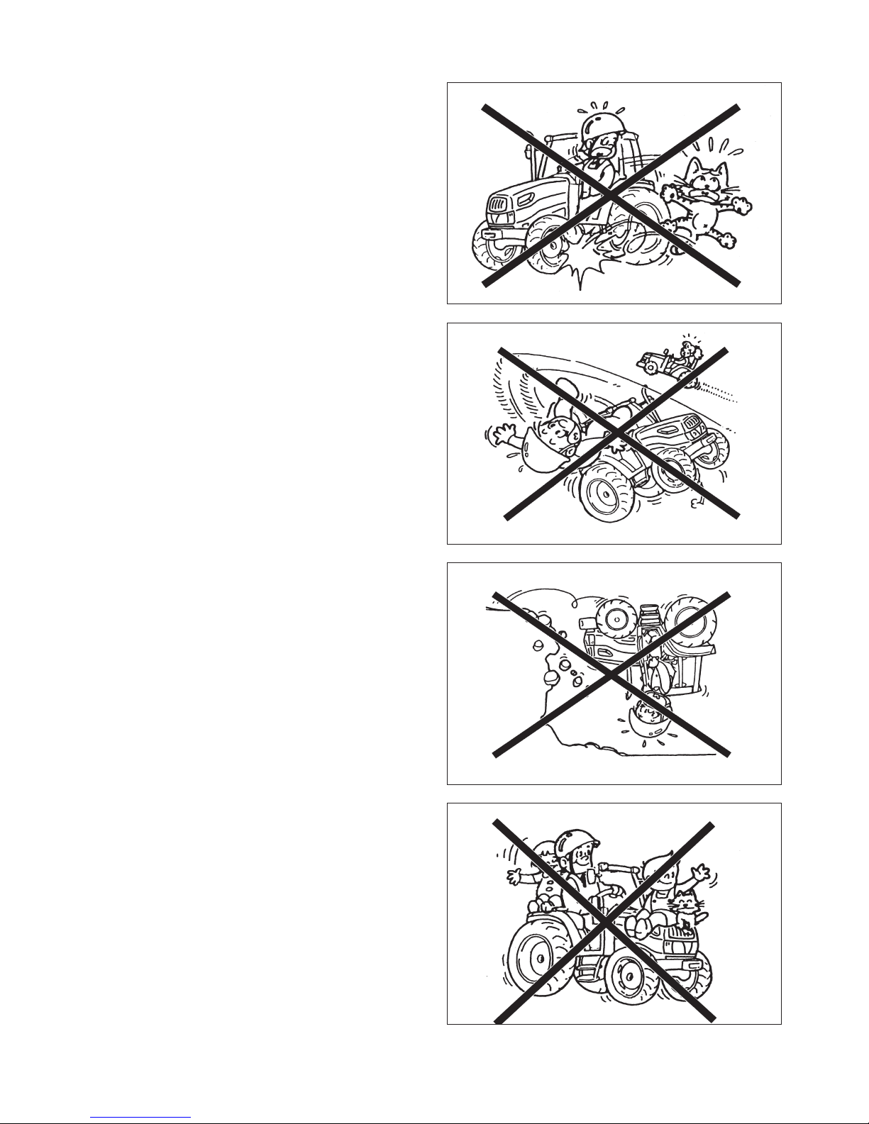
(6) Never allow other persons to get on the machine
or the implement except when the machine or the
implement is provided with a seat or a platform
for persons to sit or stand on, and only within the
capacity specified.
Never allow persons to get on the implement while
traveling on roads.
FIG. 1-10
FIG. 1-11
FIG. 1-12
FIG. 1-13
SAFETY
9
(7) When parking the tractor, you have to park it on
hard, level ground and provide sufficient safety
measures by grounding the implement, removing
the key, applying the parking brakes, and chocking
the wheels securely.
(8) Keep inflammable away from the engine during
operation. Especially during stationary operation do
not operate the engine at high speeds so as not to
set fire to grass or straw with a heated exhaust pipe
or exhaust fumes.
(9) When you have to operate the tractor at night, make
sure of the location of the control levers and pedals.
If no t, the tractor mig ht work unexpect edl y b y
mistake.
LOADING ONTO OR UNLOADING FROM A TRUCK
(1) When loading the tractor onto a truck or a trailer,
turn off the truck`s engine and apply the parking
brakes to the truck or the trailer.
Otherwise, the truck could move and the tractor falls
to the ground.
(2) Pay sufficient attention to the safety conditions
around the tractor and have it guided by someone
to assist the operation. Never allow other persons to
approach the tractor, especially in front of or behind it.
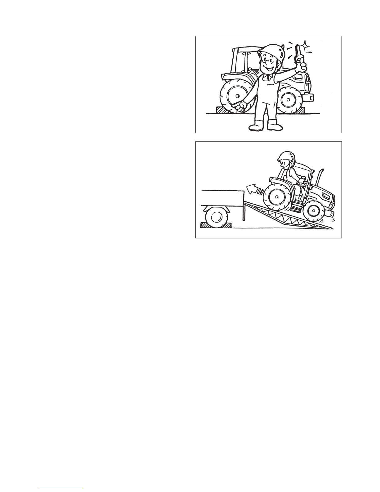
(3) When loading or unloading the machine on/off a
truck, set slip-proof ramps at the same angles and
drive the tractor straight at sufficiently slow speeds.
Loading the tractor in reverse travel and unloading
it in forward travel.
(4) Never depress the brake pedal during loading or
unloading operation, or the tractor may shift side-
ways, which may cause it to fall of the ramps.
(5) If the engine stalls unexpectedly on the ramps,
depress the brake pedal immediately and roll the
tractor to the ground by manipulating the brake pedal.
Start the engine on the ground and try again.
(6) When the machine is loaded on the truck, stop the
engine, apply parking brakes, and withdraw the
stator key, chock the wheels, and rope it securely to
the truck. During transportation, do not make sharp
turns needlessly so as not to shift the loaded tractor.
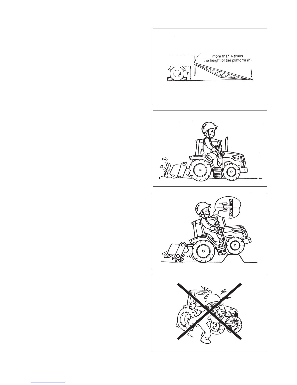
(7) Use ramps with the same or better specifications
mentioned below. When the machine is equipped
with attachments other than those included in the
specifications mentioned below, ask your ISEKI
dealer for advice.
FIG. 1-14
FIG. 1-15
TJ75
10
SPECIFICATIONS OF THE RAMPS
Length
More than 4 times the height of the platform of the truck
Width (effective width) more than 35cm
Capacity (one ramp) more than 2200kg
Ramps should have anti-skid surfaces
(8) Hook the ramps securely on the platform of the trac
tor with the top of the ramp level with the platform.
(9) Alway s prep a re for even the wors t , by n e ver
allowing other persons near the tractor.
(10) Drive the tractor carefully at the moment the tractor
moves from the ramps onto the platform, for it
changes angle abruptly.
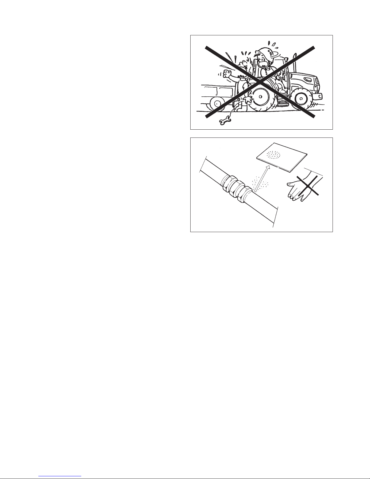
DURING OPERATION
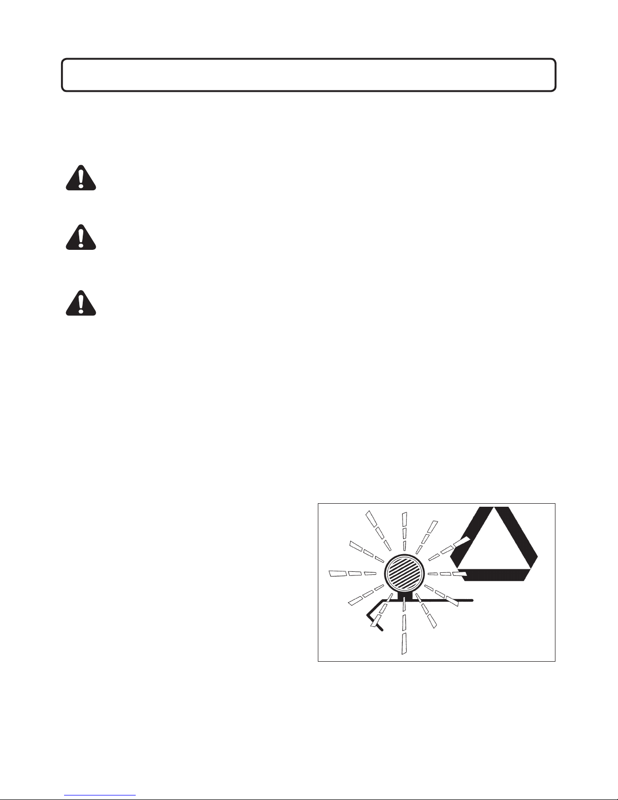
(1) During operation, never allow other persons in the
vicinity of the tractor, because the tractor itself or
flung pieces may cause injury.
(2) Pay atte n tion t o safe t y around the tracto r to
avoid injury to bystanders or damage to property.
Especially when operating with other persons, use
the horn to warn them.
(3) When crossing a ditch or a levee or when passing
through soft land, drive the tractor slowly an d
straight so that it dose not slip or turn over.
(4) Do not touch dangerous parts such as rotating
parts, moving parts, hot parts (muffler, radiator, or
engine, etc.), or electric parts (battery terminals and
other live parts), or you may be injured seriously.
(5) If you use a trailer, use a proper one which suits
your tractor. Using an improper trailer may cause
serious accidents. Never attempt to haul beyond
the tractor`s capacity. If you have a question, please
consult ISEKI dealer.
FIG. 1-16
FIG. 1-17
FIG. 1-18
FIG. 1-19
SAFETY
11
(6) When moving the machine toward an implement
for the purpose if installing the implement, never
allow any one to stand in between. When installing
the im ple ment on the machine, be prepare to
move away promptly in the event of an emergency.
The brakes shoul d be applied securel y d uring
installation.
INSPECTION AND MAINTENANCE
(1) When servicing the tractor or mounting or dismount-
in g an impl ement , place t he tra ctor on lev el,
hard ground which is sufficiently illuminated, or
unexpected accidents may occur.
(2) When servicing the tractor, follow the instructions
listed below:
・Stop the engine.
・Apply parking brakes.
・Disengage all PTO.
・Place all gear shift levers in neutral.
・Remove the starter key.
・Lower the implement fully, if equipped.
If not, your hands or clothes may be caught or
sandwiched between.
(3) When ser vicin g the tra ctor, use pro per t ools.
Using makeshift tools may lead to injuries or poor
servicing, which may result in unexpected accidents
during operation.
(4) The engine, muffler, radiator, etc. are very hot
just after operation, so wait until they cool down
sufficiently to avoid burns.
(5) Never remove the radiator cap while the engine is
hot or running. Wait until the engine cools down and
then relieve the radiator pressure by releasing the
radiator cap. Carelessly pouring cooling water into
the heated radiator can cause serious damage to
the radiator and the engine. Careless removal of
the radiator cap can cause serious injury because
of overheated water vapour.
(6) Never fit unauthorized implements or attempt unau-
thorized modification.
(7) Be sure to reinstall the removed safety covers in
place as exposed dangerous parts may cause seri-
ous injury.
(8) Avoid high-pressure fluids. Escaping fluid under pres-
sure can penetrate the skin and cause serious injury, so
keep hands and body away from pin holes and nozzles
ejecting such fluids. Be sure to consult your dealer
about the hydraulic and fuel injection system trouble.
When checking for leaks, use a piece of cardboard
or wood without fail. If any hydraulic fluid is injected
accidentally into the skin, it must be removed within a
few hours by a doctor familiar with this type or injury.
FIG. 1-20
FIG. 1-21

TJ75
12
(9) When servicing wheels and tires, the tractor and/or
implement must be supported on suitable blocks or
stands. Not a hydraulic jack.
Do not attempt to service a tire unless you have the
proper equipment and experience to perform the job.
Have the work carried out by your ISEKI dealer or a
qualified repair service.
When seating tire beads onto rims, never exceed
the maximum inflation specifications specified on the
tire.Inflation beyond this maximum pressure may
brake the bead, or even the rim, with dangerous,
explosive force.
If tire have deep scratches, cuts or punctures, the
replaced by qualified personnel as soon as possible.
Wear suitable protective clothing, gloves, eye/face
protection.
STORAGE
(1) Never cover a hot machine just after operation with
a tarpaulin or the like, or the heated engine and
related parts may cause a fire.
(2) Before storing the tractor for a long period of time,
disconnect the battery cables to prevent them, in
case they are gnawed by a rat, from causing a short
circuit, which may lead to a fire. When disconnecting
the cables, disconnect the negative (-) cable first.
(3) Safe storage of dangerous objects
・When storing dangerous implements, take appro-
priate safety measures to prevent accidents by
covering with tarpaulin.
・Store fuel in a safe place with caution signs such
as PREVENT FIRE or INFLAMMABLE.
・All inflammable must also be stored in a safe,
fireresistant location.
FIG. 1-22
SAFETY
13
MAINTENANCE OF THE ELECTRIC SYSTEM
TO MAINTENACE ELECTRIC WIRING
(1) When servicing the electric wiring, stop the engine
without fail. Otherwise your hands or clothes may
be caught in or sandwiched between rotating parts.
(2) Before manipulati ng electr ic parts, be sure t o
disconnect the earth battery cable (-), or you may
get an electric shock or be injured by sparks.
(3) Loose electric terminals or connectors may not only
lower electrical performance but also cause short
circuit or leakage of electricity, which may lead to a
fire. Promptly repair or replace damaged wiring.
(4) Remove c haff of dust from the battery, wiring,
muffler, or engine. Otherwise it could result a fire.
TO HANDLE THE BATTERY
(1) When working around the battery, avoid smoking.
The battery generates explosive hydrogen and oxy
gen gases when it is being charged.
Keep the battery away from sparks or open flames.
(2) The battery should be inspected before starting the
engine. Be careful not to touch the electrolyte when
removing the vent plugs. If the battery electrolyte
makes contact with the skin or clothing, wash it off
immediately with water and then consult a doctor.
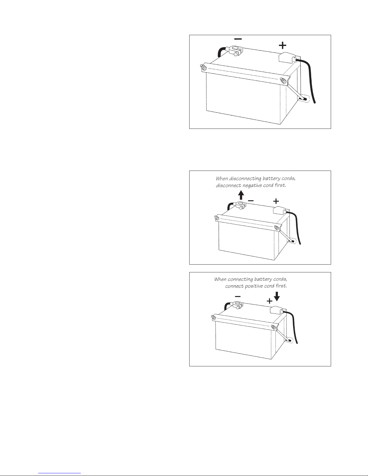
(3) When replacing or inspecting the battery, stop the
engine and turn the main switch off, or electrical
parts may be damaged or unexpected accident may
occur.
When disconnecting the battery cables, disconnect
the earth cable (-) first without fail. When connecting
the battery cables, connect the positive cable (+) first.
Disconnecting or connecting in wrong order may lead to
a short circuit or sparks.
FIG. 1-24
FIG. 1-25
FIG. 1-23

TJ75
14
TO HANDLE BOOSTER CABLES
Wh e n using boos ter cab l es, pay a ttent i on to t h e
following items for safe operation:
(1) Before connecting cables, remove the vent plugs.
This will lower the force in case of explosion.
(2) Before connecting cables, be sure to stop the engine.
Otherwise unexpected accidents may occur.
(3) Use booster cables with sufficient electrical capacity.
A cable of inadequate capacity will cause generation
of heat, which may lead to a fire.
SAFETY DECALS
The labels are stuck on the tractor. You should of course
read the safety instructions in the manual. But never fail
to read the labels on the machine as well.
・The labels should always be clearly seen, that is,
nothing should obscure them.
・When they have become dirty, wash them with
soap water and wipe off with soft cloth.
・If any of them are torn or lost, order new labels
from your dealer. Their codes are mentioned in
SAFETY DECALS AND THEIR LOCATION.
・A new label should be placed in the same place
where the old one was located.
・When sticking on a new label, clean the place to
enable the label to stick and squeeze out all air
bubbles trapped under it.
SAFETY
15
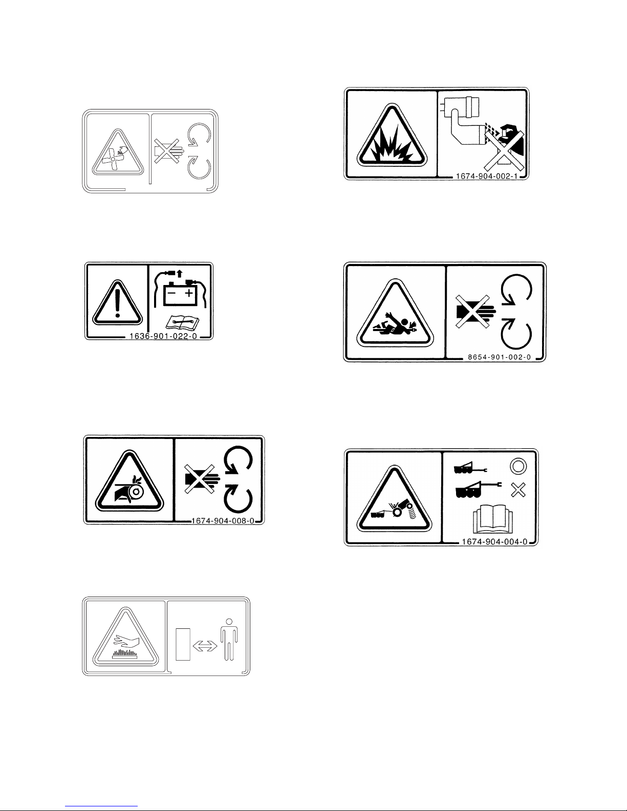
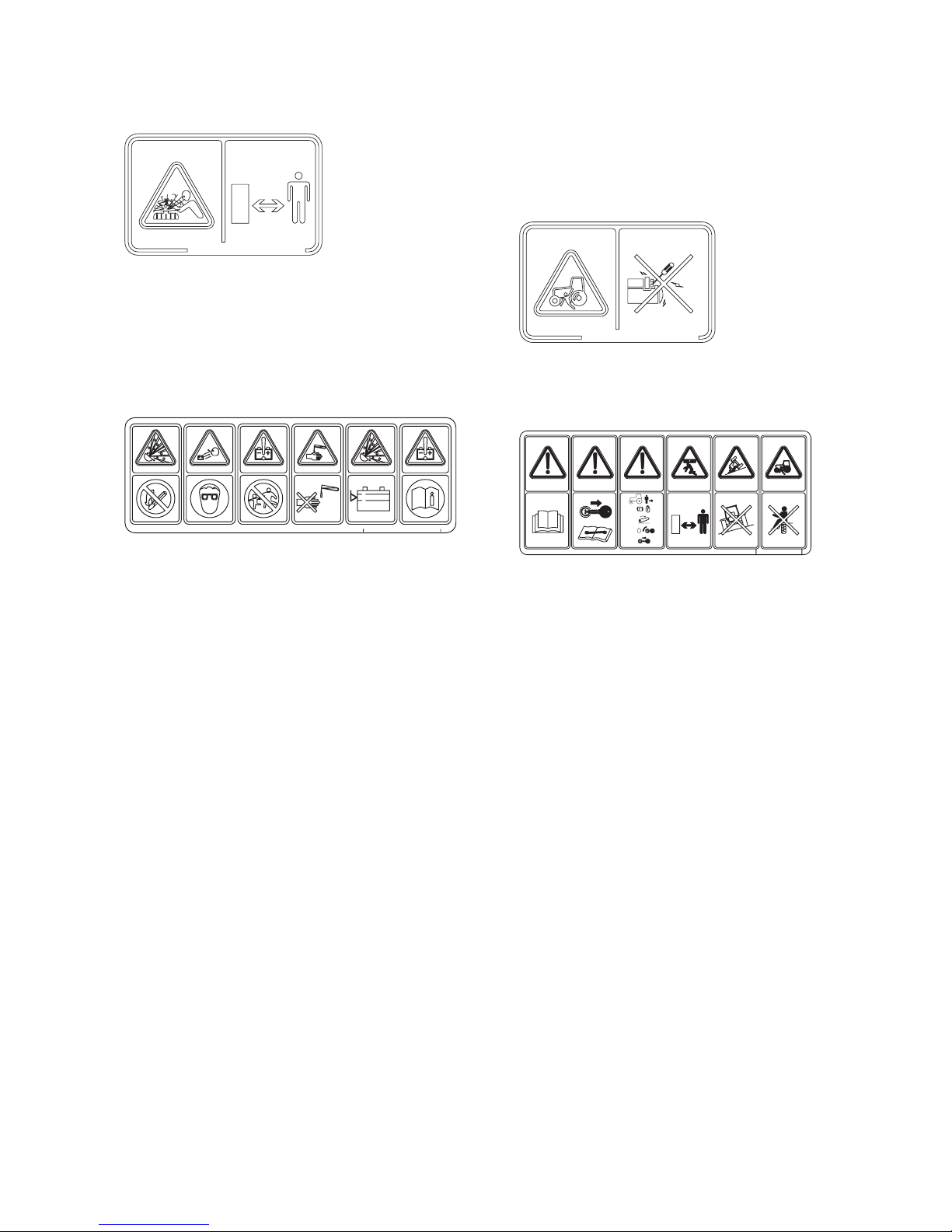
SAFETY DECALS AND THEIR LOCATIONS
(1) Fan warning label
(Code No. 1705-902-006-0)
WARNING: RISK OF ENTANGLEMENT
Stay clear of the fan while it is running.
(2) Battery disconnecting label
(Code No.1636-901-022-0)
WARNING: RISK OF ELECTRIC SHOCK
When disconnecting the battery, detach the negative
terminal first and attach the positive terminal first
when connecting the battery.
(3) Belt warning label
(Code No.1674-904-008-0)
WARNING: RISK OF ENTANGLEMENT
Stay clear of the belt while it is running.
(4) Hot part warning label
(Code No.8595-901-007-0)
WARNING: HOT SURFACES, RISK OF BURNS
ON HANDS AND FINGERS
Stay clear of the heated parts until they cool down
sufficiently.
(5) Ether label
(Code No.1674-904-002-1)
WARNING: RISK OF EXPLOSION
Ether or other starting fluid should never be used to
start engines equipped with glow plugs.
(6) PTO label
(Code No.8654-901-002-0)
WARNING: RISK OF ENTANGLEMENT
Stay clear of the PTO shaft while the engine is
running.
(7) Trailer label
(Code No.1674-904-004-0)
WARNING: RISK OF OVERHEATING
The rear implement should be installed on the
tractor with an approved drawbar or by using the
lower links of the three point hitch. Use only weight
not exceeding the designed capability of the tractor.
㧝㧣㧜㧡㧙㧥㧜㧞㧙㧜㧜㧢㧙㧜
㧤㧡㧥㧡㧙㧥㧜㧝㧙㧜㧜㧣㧙㧜
TJ75
16
(8) Radiator label
(Code No.1705-902-008-0)
WARNING: HIGH PRESSURE STEAM AND HOT
WATER
Never remove the radiator cap during or just after
operation. The water in the radiator is very hot and
highly pressurized, which could cause burns.
(9) Battery label
(Code No.1705-904-002-1)
A. WARNING: RISK OF EXPLOSION
Keep away from sparks or flames, which could
cause explosion.
B. WARNING: WEAR AN EYE PROTECTION DEVICE
Batte ry electroly te (eupho ric aci d) may cause
blindness. Wear an eye protector to prevent contact
with the eyes.
C. WARNING: KEEP OUT OF REACH OF CHILDREN
D. WARNING: RISK OF BURNS
Battery elect rolyte (sulphu ric acid) may cause
burns. Avoid contact with skin or clothing. In case
of an accident, flush affected part immediately with
plenty of water.
E. WARNING: RISK OF EXPLOSION
Never use the battery with the electrolyte surface
below the “LOWER” limit, or it may explode. Never
replenish exceeding “UPPER” limit or electrolyte
may leak out.
Maintenance free battery does not need to replenish
distill water.
F. WARNING: READ OPERATION MANUAL
Read the safety and operating instructions in the
operation manual before operating the tractor.
Take care of handling the battery.
Improper handling may lead to explosion.
Never short the poles.
Charge the battery in a well ventilated place.
(10) Starter warning label
(Code No.1705-902-007-0)
DANGER: RISK OF ELECTRIC SHOCK
Start the engine only from the seat using the key.
(11) Operation caution label
(Code No.1674-904-001-0)
A. WARNING: BEFORE OPERATION
Read the safety and operating instructions in the
operation manual before operating the tractor.
B. WARNING: BEFORE OPERATION
Read the safety and operating instructions in the
operation manual before operating the tractor.
C. WARNING: RISK OF ABRUPT MOVING
Bef o r e leavin g the tra c t or unatta c hed, appl y
the parking brake, lower the implement, turn off
the engine and remove the starter key to avoid
unexpected moving of the tractor.
D. WARNING: RISK OF INJURY OR DAMAGE
Pay attention to safety around the machine to avoid
injury to bystanders or damage to properly.
E. WARNING: RISK OF OVERTURNING
Never operate the tractor on a slope of over 10
degrees, or it could overturn.
F. WARNING: RISK OF INJURY OR DAMAGE
Never allow other persons to get on the tractor or
the implement.
㧝㧣㧜㧡㧙㧥㧜㧞㧙㧜㧜㧤㧙㧜
㧝㧣㧜㧡㧙㧥㧜㧠㧙㧜㧜㧞㧙㧝
㧴
㧸
㧝㧣㧜㧡㧙㧥㧜㧞㧙㧜㧜㧣㧙㧜
㧝㧜q㧗
㧝㧢㧣㧠㧙㧥㧜㧠㧙㧜㧜㧝㧙㧜
㧝㧚
㧟㧚
㧠㧚
㧞㧚
㧿㨀㧻㧼
SAFETY
17
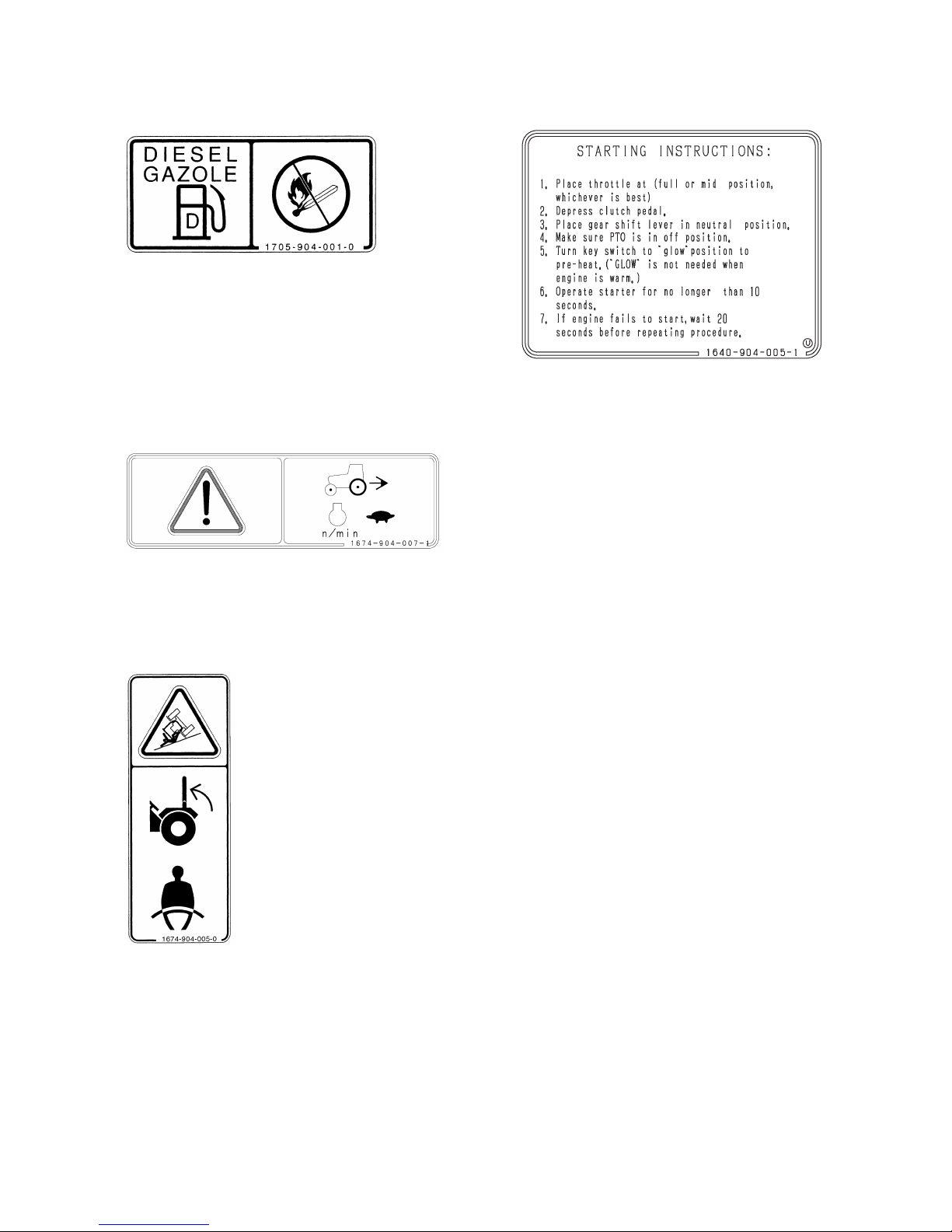
(12) Fuel label
(Code No.1705-904-001-0)
DANGER: RISK OF EXPLOSION AND BURNS
Use only diesel fuel.
Before replenishing fuel, be sure to stop the engine
and wait until the engine and heated parts cool
down sufficiently. Keep sparks, open flames, etc.
way from the fuel tank.
No smoking!
(13) Reverse label
(Code No.1674-904-007-1)
Before moving tractor to reverse direction, be sure
to reduce engine speed.
(14) ROPS label
(Code No.1674-904-005-0)
(ROPS/CABIN type)
WARNING: RISK OF INJURY
Keep the ROPS in the upright position and fasten
the seat belt at all times. Do not jump from the seat
if the tractor starts to overturn, or you could be
crushed under the tractor. The ROPS should usually
be kept in the upright position during operation.
However, when the ROPS has to be lowered, do
not wear the seat belt and operate the tractor with
extreme caution.
Do not operate the tractor w ith a damaged or
modified ROPS/CABIN.
(15) Starting engine caution label
(Code No.1640-904-005-1)
WARNING: RISK OF INJURY
"Before starting engine, be make sure to set throttle
lever in full or mid position.
Depress clutch pedal and set shuttle and shift lever and
PTO lever(switch) in neutral position.
When engine is cold, turn key switch to glow position to
pre-heat.
Operate starter within 10 seconds.
If engine does not start, repeat above procedure after 20
seconds."
TJ75
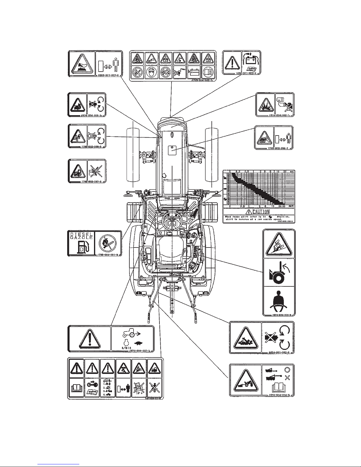
18
LOCATION OF SAFETY DECALS
Location of all instruction decals provided as a reference.
Replace any decals that are damaged, missing or are
not readable. Consult your dealer.

INTRODUCTION
19
INTRODUCTION
The information in this publication describes the operation, maintenance and servicing of the TJ75 Tractor. Every
effort has been made to provide correct and concise information to you, the operator, as available at date of book
publication. Your ISEKI Dealer is available should items in this book or details of your machine not be understood.
This book is supplied with each machine to familiarize the operator with proper instructions needed for operation and
maintenance. Studying and adhering to these instructions will insure optimum machine performance and longevity. A
machine that is maintained properly and operated in the intended manner will provide greater dividends than one that
is neglected and/or operated in manner other than as intended. Design and servicing of this machine has been kept
as simple as possible to permit maintenance operations to be carried out with tools normally available.
This book should be thoroughly read and understood prior to operation of this machine. Inexperienced operators
should study contents of this publication and receive instruction from an experienced operator when possible. Your
ISEKI Dealer can also assist in areas concerning machine operation and provide details concerning safe operation. it
is suggested that this booklet be kept readily accessible, preferably with the machine, for future reference if questions
or concerns arise. If the original book should become damaged, consult your Dealer in regards to acquiring a
replacement.
Customers are strongly advised to use an official ISEKI Dealer in connection with any service problems and
adjustments that may occur. The ISEKI Dealer network is specially trained and equipped for all service work and to
advise customers on specific applications of the Tractor in local conditions.
CAUTION: In some of the illustrations used in this Operator Instruction Book, panels or guards may
have been removed for clarity. Never operate the Tractor with these panels and guards removed. If
the removal of a shield is necessary to make a repair, it MUST be replaced before operation.
CAUTION: READ THIS BOOK IN ITS ENTIRETY PRIOR TO OPERATING MACHINE.
Use only ISEKI parts for repairs and/or replacement.
TJ75
20
TRACTOR IDENTIFICATION
MODEL/SERIAL NUMBER
Each Tractor is identified by means of Tractor model and
serial numbers. As a further identification, engine and
chassis are provided with identification numbers.
To ensure prompt, efficient service when ordering parts
or requesting repairs from authorized Dealer, record
these numbers in spaces provided.
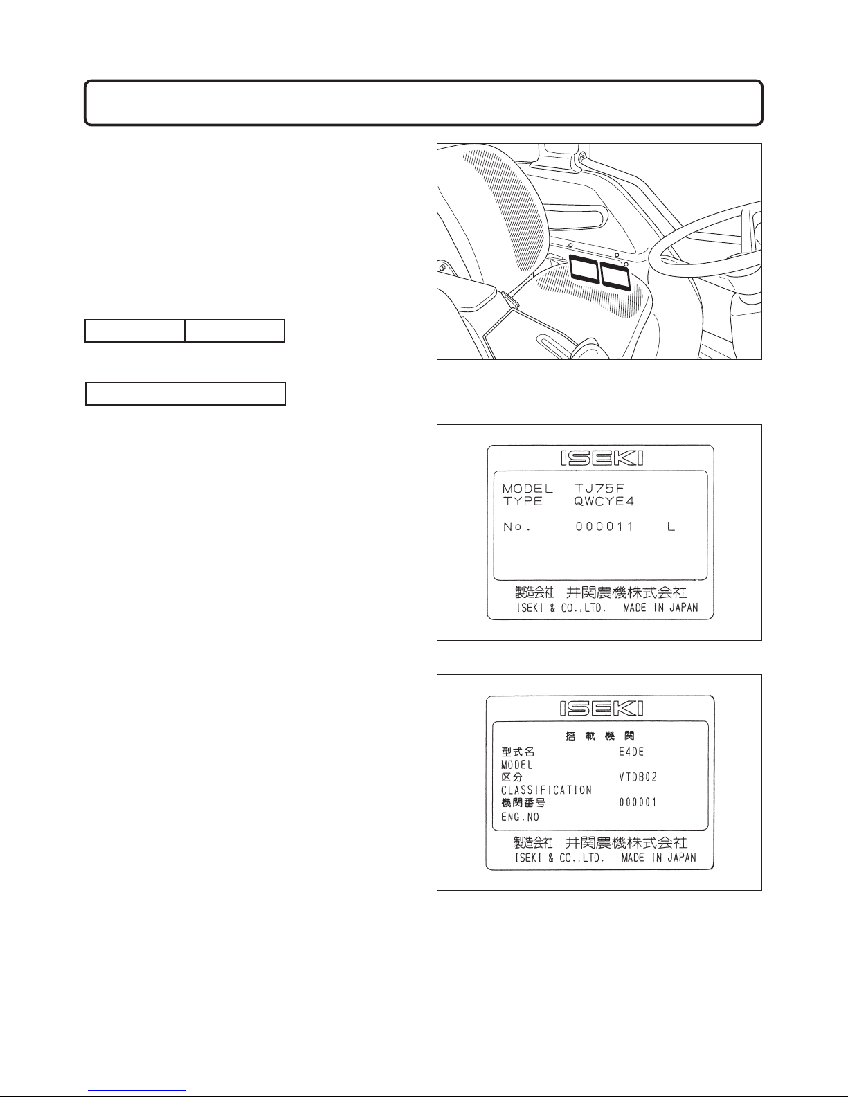
TRACTOR MODEL/TYPE
TRACTOR SERIAL NUMBER
FIGS. 3-1, 3-2, 3-3: Tra ctor identif icati on plate, 1 ,
located below operator's seat on right-hand side of
fender. Contains model number in addition to Tractor
serial number.
FIG. 3-1
FIG. 3-2
FIG. 3-3

TRACTOR IDENTIFICATION
21
ENGINE MODEL NUMBER
ENGINE SERIAL NUMBER
FIG. 3-4: Engine model number, 1, is cast on right side
of engine block, below the injection pump.
Engine serial number, 2, is stamped into cylinder block,
below engine model number.
CHASSIS NUMBER
FIG. 3-5: Chassis number, 1, is stamped in right side of
front frame.
NOTE: Reference to left-hand and right-hand, used
throughout this book, refers to the position when
seated in operator's seat and facing forward
FIG. 3-4
1
2
FIG. 3-5
1
TJ75
22
FIG. 3-6
㧣 㧣
ޓޓ
ޓ
㧯
㧻
㧮
㧻
ޓޓޓ
㧜
㧢
㧚㧝
㧟㧣
㧿㧭㧱ޓ㧭
ޓ㧟
㧡
ޓ㧰㧻㨀
㧵
㧭ޓ
㧱
㧟
ޓ
㧜㧞ޓ
㧡
㧝
㧣㧟㧠ޓ㧵㨑
㧟
ޓ
ޓ
ޓ㧯
㧻
㧮
㧻ޓ
ޓޓ
㧜
㧢
㧚㧝㧟
㧣
㧿㧭㧱ޓ
㧭
ޓ㧟
㧡
ޓ㧰㧻㨀
㧵㧭
ޓ
㧱
㧟
ޓ㧜
㧞
ޓ
㧡
㧝
㧣㧟㧠ޓ
㧵
㨑㧟
㧯㧻㧮㧻
㧵㨀㧭㧸㨅
㧣
㧣
㧣
㧣
29
24 25
11
4
15
14
27
21
22
23
16
1
20 18 19
5
6
7
98
13
2 17 12 10 3
28
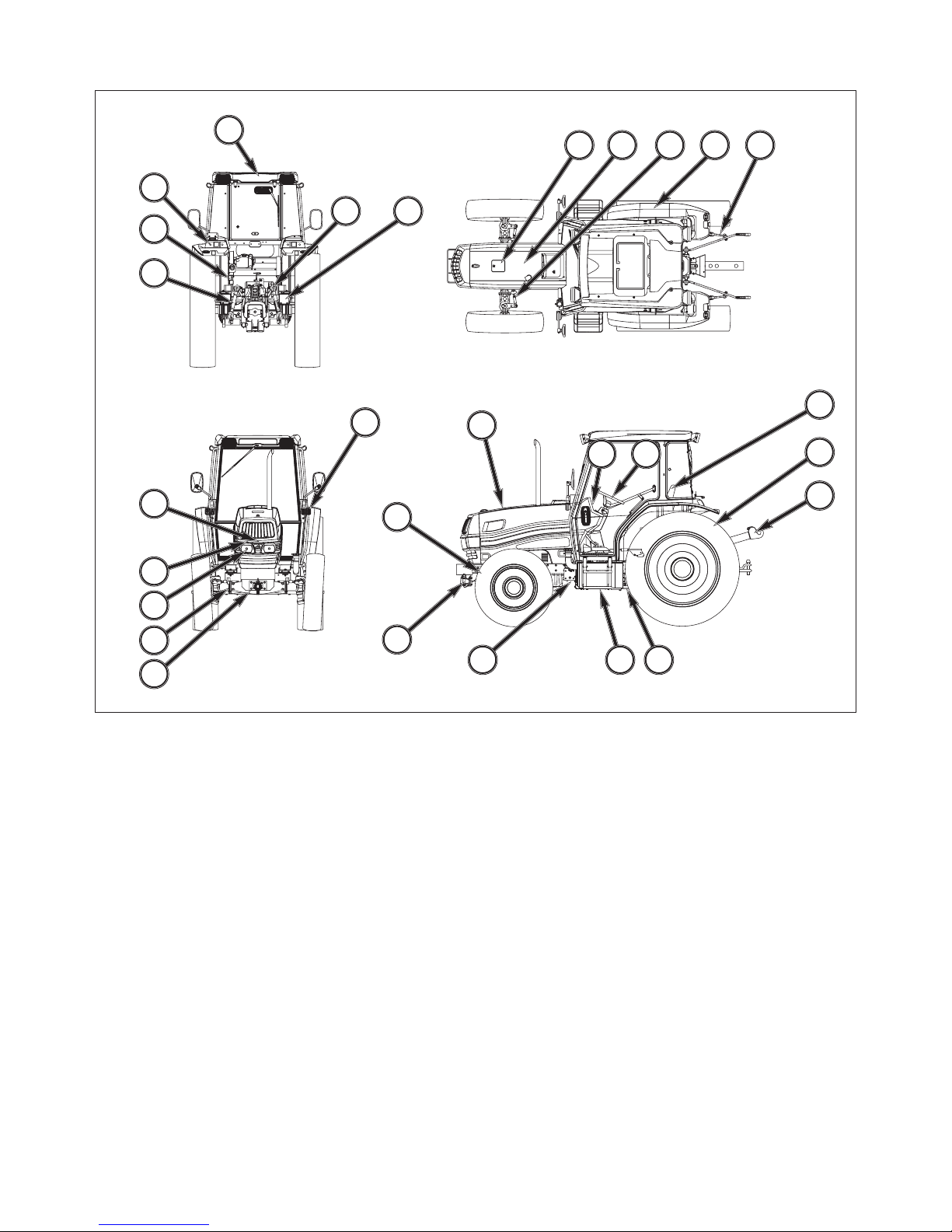
FIG. 3-6: Identification and terminology of major components, as given in this book, are as follows:
1. Front Wheels
2. Fuel Tank Filler
3. Check Chain
4. Lift Rod
5. Lower Link
6. Rear Wheels
7. Operator's Seat
8. Instrument Panel
9. Steering Wheel
10. Fender
11. Reflector
12. Steering Cylinder
13. Hood
14. Front Grille
15. Battery
16. Front Hitch
17. Engine
18. Foot Step
19. Transmission
20. Front Wheel-Drive Shaft
21. Headlight
22. Front Axle
23. Front Axle Pivot
24. Lift Arm
25. Rear Axle
26. Drawbar
27. Turn/Hazard position Light
28. Cabin
29. Turn/Reflector/Tail Light
INSTRUMENTS & CONTROLS
23
INSTRUMENTS & CONTROLS
FIG. 4-1
A
B
A
A
B
N
B
51
2
9
4
7
3
15
8
10
11
18
12
6
13
14
22
21
20
19
16
17
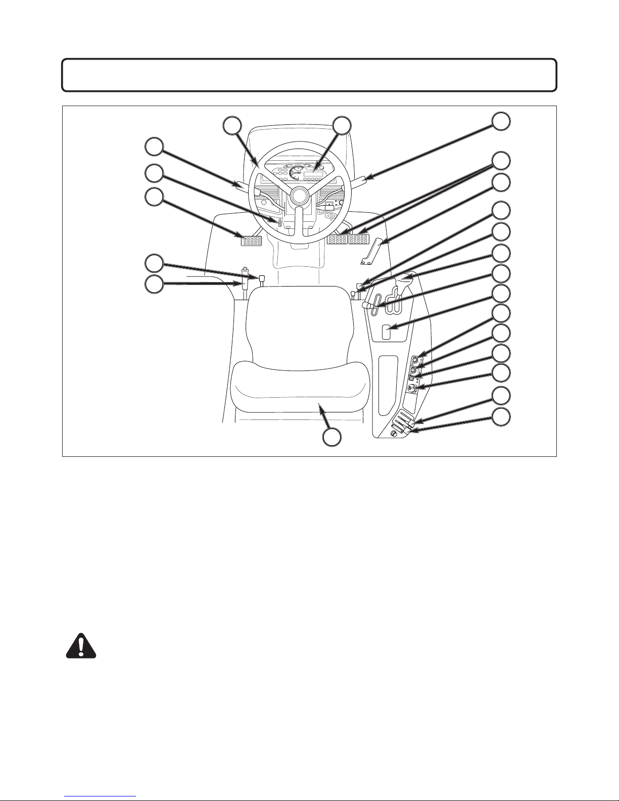
FIG. 4-1: General layout and location of controls within operator's area on Tractor. Specific use of these controls is
given later in this section and also in operationsection of this book:
1. Steering Wheel
2. Forward / Reverse Power Shuttle Lever
3. Parking Brake Lever
4. Clutch Pedal
5. Instrument Panel
6. Range Shift Lever (with Gear Shift Button)
7. Rear Power Take-Off (PTO) Selector Lever
8. Hand Throttle Lever
9. Steering Column Tilt Pedal
10. Brake Pedals
11. Foot Throttle Pedal
12. Differential Lock Pedal
13. Three Point Hitch Position Control Lever
14. Three Point Hitch Position Control Switch
15. Operator's Seat
16. External Auxiliary Hydraulics Lever
17. External Auxiliary Hydraulics Lever
18. Four wheel Drive (4-WD) Shift lever
19. Power Take-OFF (PTO) switch
20. Power Take-OFF (PTO) Mode Switch
21. Highest Position Adjustment Dial
22. Lowest Position Adjustment DialC A U T I O N : B e c o m e fa m i l i a r wi t h al l
operating controls prior to operating Tractor.
Read this book in its entirety before starting.
TJ75
24
FIG. 4-2
INSTRUMENT PANEL
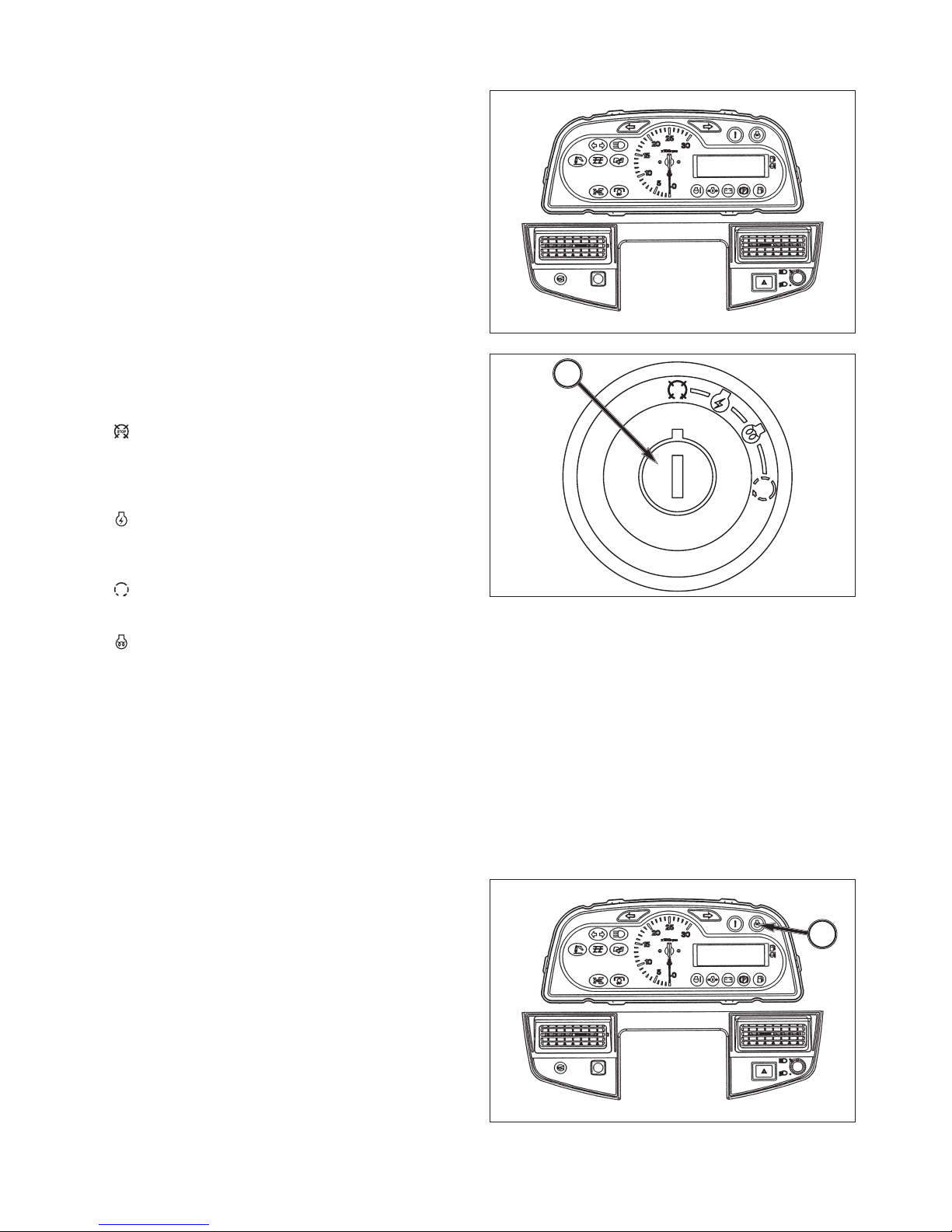
FIG. 4-2: Arrangement of gauges. Control switches and
indicators located in instrument panel. Items are detailed
in the descriptions that follow:
Electric Fuel Shut-Off
Turning main switch to OFF position will stop engine.
Main Switch
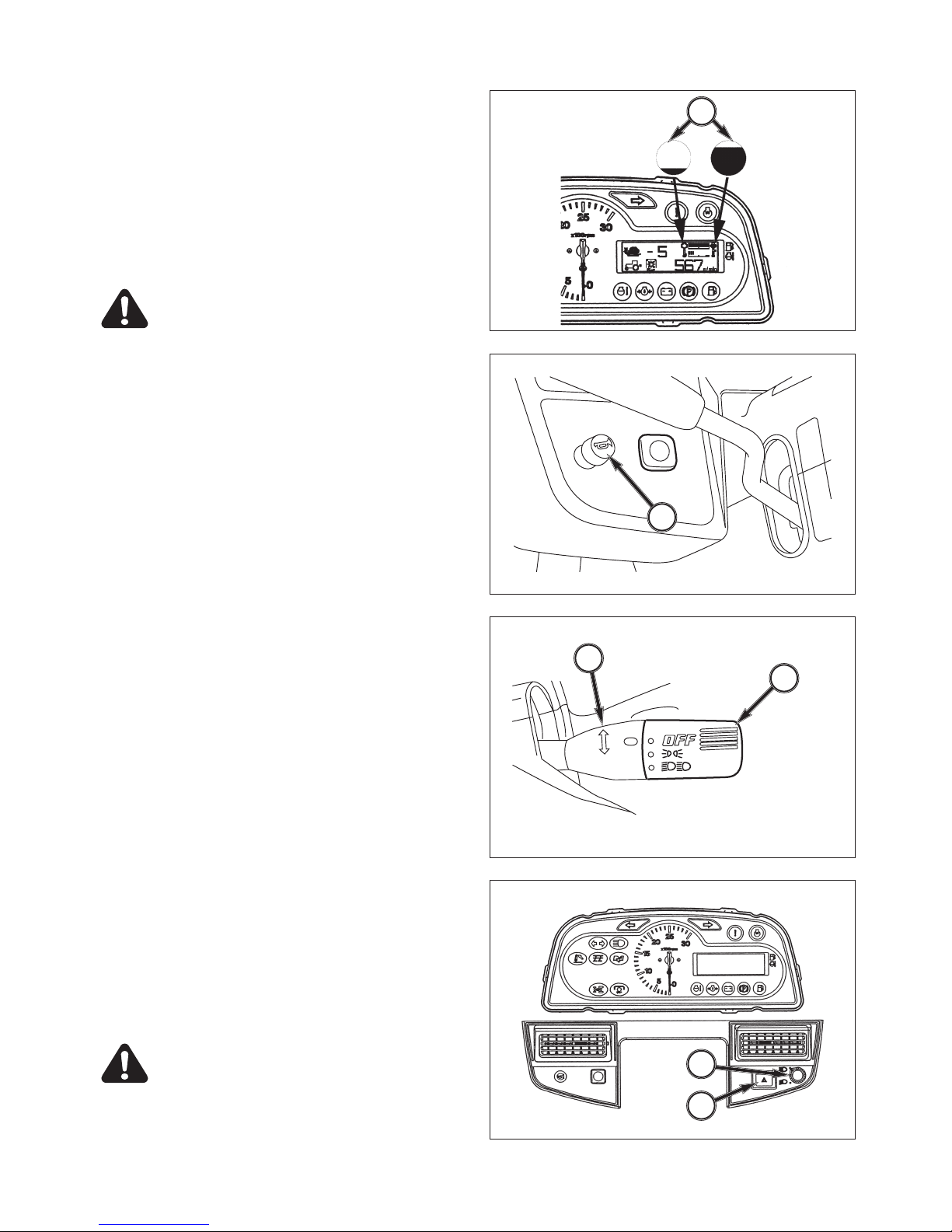
FIG. 4-3: Main switch, 1, has the four following positions:
・ OFF - Tractor engine and all electrical circuits
off.(except for head light, turn/hazard position
light, tail l i g h t , working l a m p ) Key c a n be
removed.
・ ON - P ower sup plie d to all cir cuits. Nor mal
operating position. Linkage on fuel injection pump
moves (electrically) to the run position.
・ START - Starter activated. This position spring
loaded to ON
・ GLOW - E nergizes glow plugs to pre-he a t
combustion chambers and assist starting.
NOTE: Main switch must be turned to ON before any
circuits will operate. PTO switch must be off and
gear shift lever in neutral before engine can be
started.
This tractor is equipped with an electric fuel shut
off. When main switch, 1, is turned to START,
ON, or GLOW position and gear shift lever is
placed in neutral, a solenoid moves the fuel
linkage on injection pump to run position to start
engine. When main switch is turned to OFF
solenoid moves fuel linkage to OFF position to
stop engine.
FIG. 4-4: When main switch, 1, is selected to GLOW
position, glow indicator, 2, will illuminate after several
seconds to indicate the engine combustion chambers
are preheated and allow cold engine to be started.
FIG. 4-3
㧿㨀㧻㧼
1
FIG. 4-4
2

INSTRUMENTS & CONTROLS
25
Indicator Light Strip
FIG. 4-5: Indicator light strip, 3, contains several warning
lights to m oni tor certain functions. Currently us ed
positions (from left to right) are:
・ Main (High) Beam - Illuminates when headlamps
in front grille are selected to high beam position
bylight switch.
・ Power Take-Off (PTO) - Illuminates when PTO
control switch is moved to engage PTO clutch
pack (PTO operating). Light will go out when PTO
switch is moved to off.
・ Engine Oil Pressure - Illuminates if engine oil
pressure is low. If light comes on while engine
is run nin g, s hut off engine imm ediately an d
investigate cause.
・ Battery Charge - Illuminates when main switch is
turned ON and will go out after engine starts, to
indicate battery is being charged.
・ Coolant Temperature - Illuminates when engine is
overheating. Reduce engine speed to idle, allow
to run at no load several minutes and investigate
cause( refer to "Troubleshooting").
・ Fuel - Illuminates when fuel is low level in the fuel
tank.
・ Inspection - Illuminates when hourmeter indicates
50/100/200/300/400・・・hour, please inspect
your tractor.
・ Caution - Illuminates when it is not normal with
starting engine or sensor of Power shift is not
normal.
・ Parking Brake - Illuminates when parking brake
lever is pulled up.
・ 4WD - Illuminates when 4WD is engaged by
shifting 4WD lever.
・ Trailer Indicator - Blink when turn switch is ON
with connecting 7 pins socket to your trailer or
when hazard light switch is ON.
・ Draft Monitor Lamp - Illuminate s w hen draft
control.(OPTION)
・ Lift Arm Upper Position - Illuminates when lift arm
is staying at the highest position. Blink when hyd
control is not ready and in waiting condition if
operating aux switch just after starting engine.
FIG. 4-5
3
TJ75
26
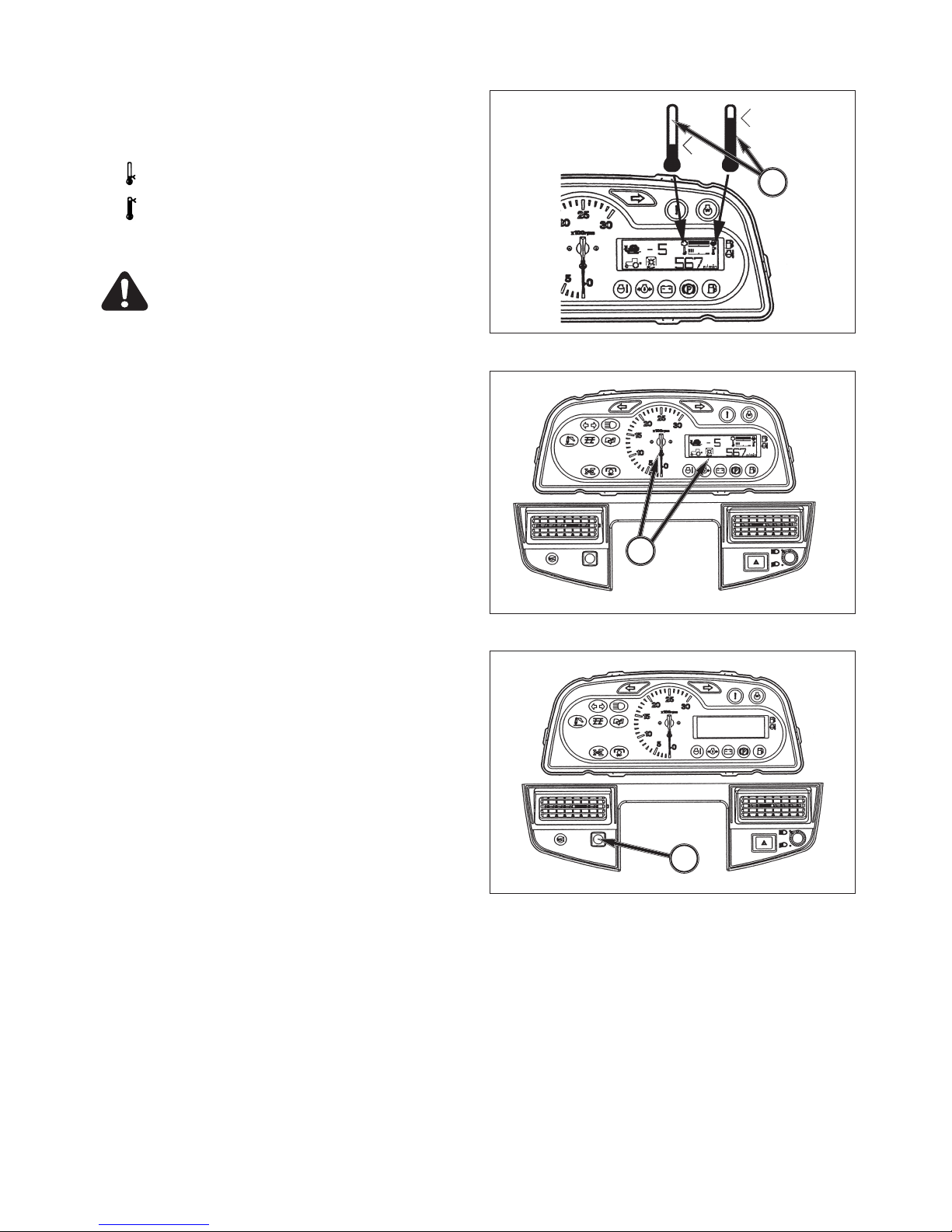
Coolant Temperature Gauge
FI G . 4-6 : Ga u ge , 4, i n d i c a te s en gi n e coo l a n t
temperature when main switch is selected to ON
・ - Shows too cool temperature for severe work.
Allow to warm before applying heavy load.
・ - Indicates overheating. Reduce engine speed to
idle, allow to run at no load several minutes and
investigate cause (refer to Troubleshooting).
CAUTION: Do not service hot engine. Allow
to com plete ly coo l befo r e serv icing or
removing radiator cap.
Tachometer
FIG.4-7 & 4-8: Scale,5, indicates engine speed in crank
shaft revolutions per minute(rpm). Digital panel indicates
not only engine revolutions but also traveling speed, rear
PTO speed, mid PTO speed, hourmeter, trip meter.
Indication of degital panel is changed by pushing the
selectable switch,6.
When rear PTO speed is 540, engine revolutions is
approximately 2430 rpm.
Normally, the PTO speed should be between 540 and
Operating the PTO at a speed above 600 is too fast, and
may result in breakdown of the tractor or implement.
The engine hourmeter is used to assist in maintenance
intervals of the tractor in 1 hour increments.
The tripmeter is used to assist in operation. The extreme
right digit indicates 1/10 hour increments. To reset the
tripmeter, push the selectable switch for two seconds.
FIG. 4-6
4
FIG. 4-7
5
FIG. 4-8
6
INSTRUMENTS & CONTROLS
27
Fuel Gauge
FIG. 4-9: Scale, 7, indicates level of diesel fuel in fuel
tank when main switch is ON.
NOTE: Use only clean diesel fuel and clean area to
pre-vent dirt/water entry into fuel tank when
refilling.DO NOT run out of fuel as bleeding air
from the system will be required. Keep fuel tank
full to minimize condensation.
CA UTION : DO NOT ref ill fuel tank with
engine running or hot. Allow cooling period.
DO NOT smoke near fuel tank. Clean up any
spilled fuel.
Horn Switch
FIG. 4-10: Horn Switch.
Horn Switch, 8 - Horn will sound when switch button is
depressed.
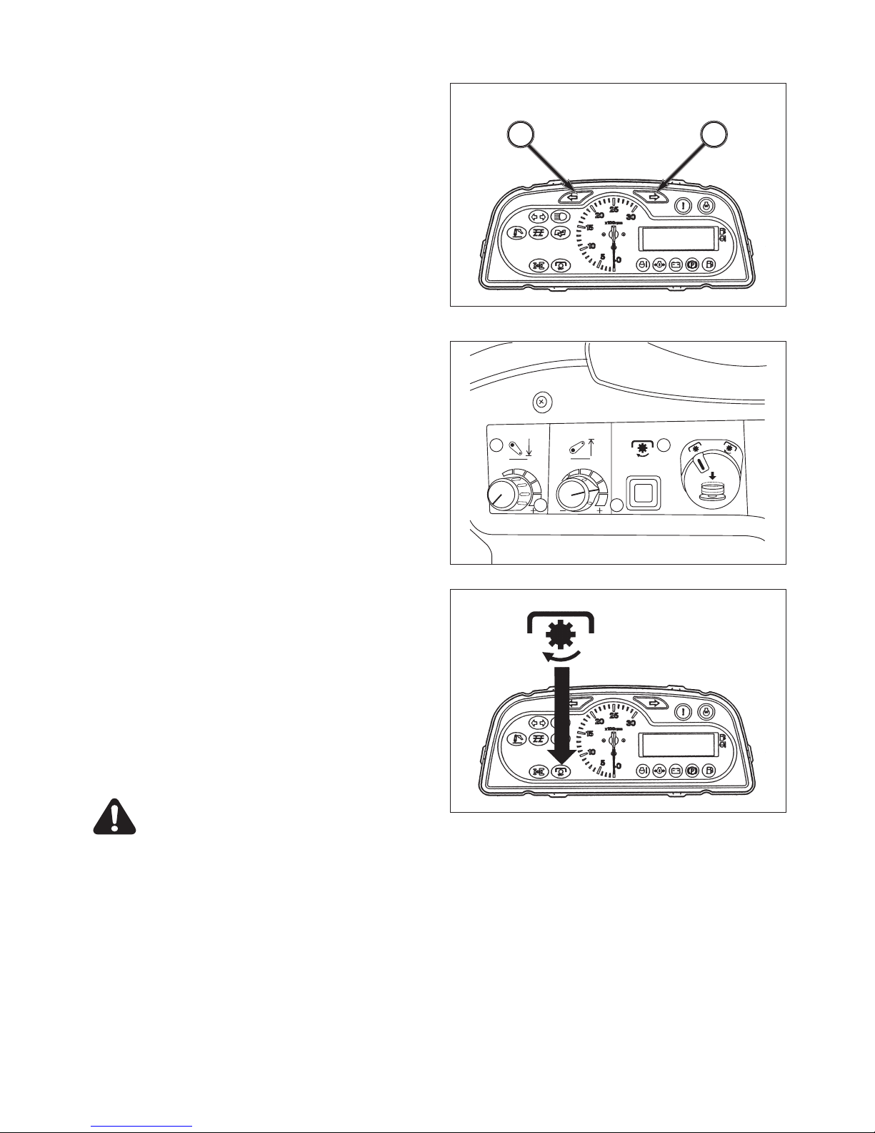
Light Turn Switch
FIG. 4-11: Light Turn Switch.
Light Switch, 9 - Is a select switch with three operating
positions by turning a top part of switch:
・ OFF - Fully counterclockwise. All lights off.
・ 1st - Front and rear position lamps.
・ 2nd - Headlamps and rear tail lights.
Turn Switch, 10 - Operate switch handle in direction
Tractor is being turned.
NOTE: Turn lights will not self-cancel. Select turn/
hazard light switch to center position after
completing turn.
High - Low Beam Switch
FIG. 4-12: Turn high-low beam switch, 11, to select high
beam or low beam.
NOTE: When high beam is selected light in indicator
light strip will come on.
Hazard Light Switch, - Press switch, 12, to turn on
hazard lights.
CAUTION: Hazard lights must be used any
time Tractor is driven on public roadway.
Consult local agencies for other marking
requirements.
FIG. 4-9
7
FIG. 4-10
8
FIG. 4-11
9
10
12
11
TJ75
28
FIG. 4-13: Turn/hazard indicator lights, 13 and 14
Power Take-Off (PTO) Switch
FIG. 4-14 & 4-15: PTO switch, 1, is used to engage and
disengage the PTO drive system.
The switch must first be turned to right and then pulled
up to engage PTO. When engaged, the PTO indicator
light in the indicator light strip will illuminate.
A PTO select switch, 2, is used to adjust PTO clutch
modulation.
Push on: soft start (button depressed and illuminated)
- for high inertia loads
Push off: standard start (button out and not illuminated)
IMPORTANT: PTO switch is equipped with a lock-out
to prevent accidental engagement of
PTO system. To engage PTO, first turn
switch clockwise and then pull up it. DO
NOT FORCE SWITCH.
NOTE: PTO switch, 1, must be used in conjunction
with rear PTO selector lever, to lower left of
operator's seat, when rear PTO is used. Refer
to operationsection for complete details.
When PTO switch is ON, the engine cannot be
started. Always switch off PTO and depress
main clutch pedal to start engine.
WARNING: Always shut off PTO and shut off
Tractor engine before servicing PTO-driven
implement. Allow all movement and motion
to stop before leaving operator's seat.
FIG. 4-13
1413
FIG. 4-14
FIG. 4-15
INSTRUMENTS & CONTROLS
29
FIG. 4-19
MAIN CLUTCH PEDAL
FIG. 4-16: Foot pedal, 1, dis engages engine from
transmission when fully depressed, to permit engine
starting, selecting/changing gears and stopping Tractor
movement. Four-wheel drive selection also requires
clutch disengagement.
Slowly raising the pedal will engage clutch and start
Tractor moving in selected gear.
NOTE: Clutch pedal should be depressed quickly to
prevent abnormal wear. Clutch pedal should be
raised smoothly to prevent sudden movement.
DO NOT ride clutch pedal with your foot.
IMPORTANT: Clutch pedal free-play must be adjustment
correctly. Refer to maintenancesection.
BRAKES
Brake Pedals & Parking Brakes
FIG. 4-17: Inner brake pedal, 1, and outer brake pedal, 2,
independently control the respective left and right wheel
brakes, to assist in turning.
During Tractor transport or high speed operation, brake
pedals must be latched together using interlocking plate,
3.
CA UTIO N: Do not use indi vidu al wh eel
brakes for transporting or operating at high
speed. Always latch pedals together using
interlocking, plate, 3. Make sure brakes are
adjusted evenly.
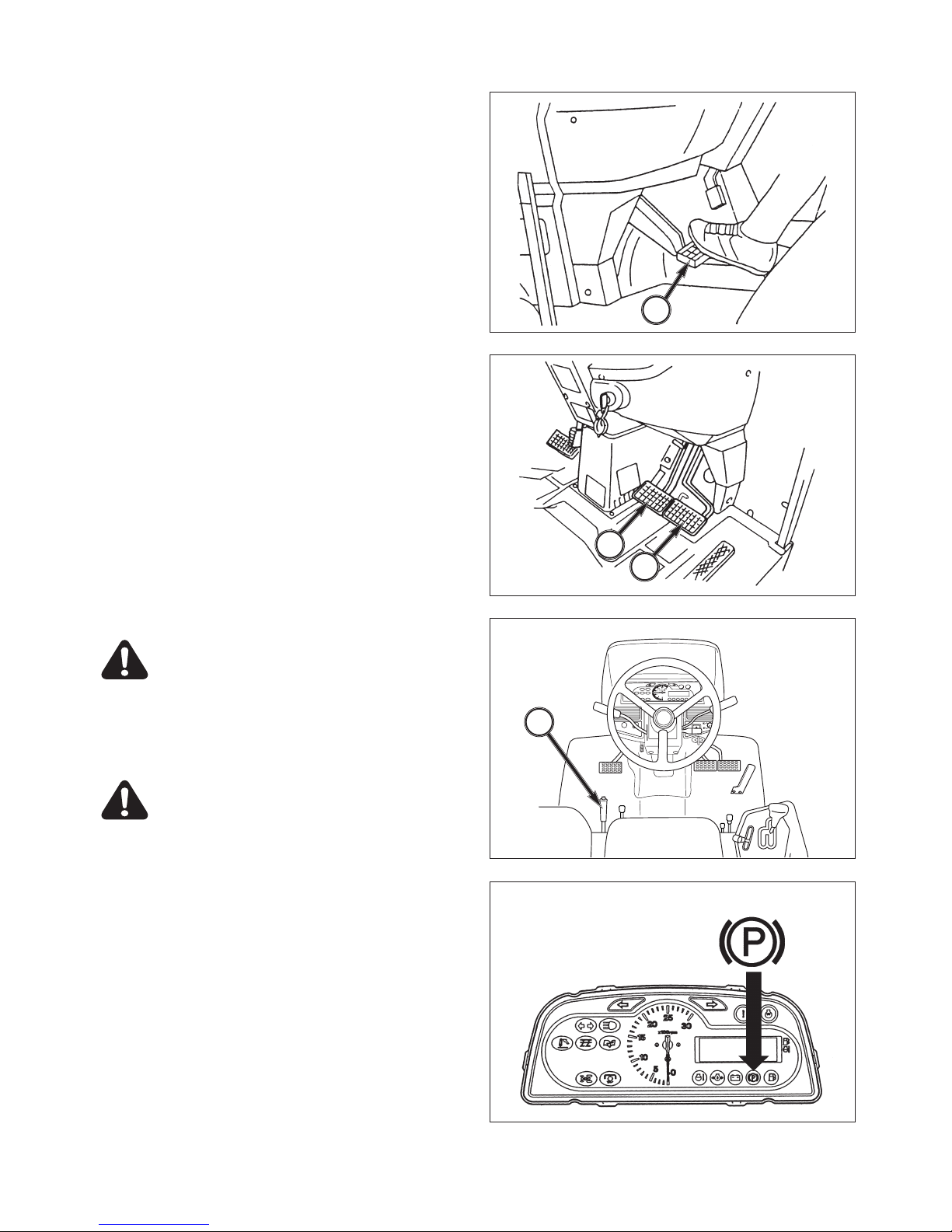
Parking Brake lever
WARNING: ALWAYS apply the parking brake
before dismounting from the tractor.
FIG. 4-18 & 4-19: The parking brake acts on the tractor
rear wheels. To engage the brake, pull upward on the
parking brake lever, 4 to lock brakes in applied position.
To release the parking brake, press the button on the
end of the lever and push the lever down.
When pulling upward on the parking brake lever, the
parking brake indicator light will illuminate.
Ensure the parking brake is fully released before driving
off.
FIG. 4-16
1
FIG. 4-17
1
2
FIG. 4-18
4
 Loading...