


Thank you very much for purchasing an ISEKI tractor.
This operator’s manual provides the information necessary for operating and maintaining
your tractor safely and properly. The contents are mainly composed of the following two
items:
Safety instructions: Essential items which you should observe while
operating the tractor
Technical instructions: Essential items which you should observe while
operating the tractor
Before starting to operate the machine for the first time, you should read this operation manual thoroughly and carefully until you are sufficiently familiar with the operation of the
machine to do jobs safely and properly. The manual should be kept in a handy place so you
can refer to it when required. You are advised to refer to it from time to time to refresh your
understanding of the machine.
Your dealer has performed the pre-delivery service on your new machine.
He will discuss with you the operating and maintenance instructions gives in this manual, and
instruct you in the proper and varied applications of this machine. Call on him at any time
when you have a question, or need equipment related do the use of your machine.
Paragraphs in the manual and labels on the machine which are
accompanied by a caution particularly important information about
safe operation to avoid accidents. You should always keep precautions in mind and follow them during operation.
Be sure to wear
personnel protective equipment
during operation
In some of the illustrations used in this operation manual, panels or
guards may have been remove for clarify. Never operate the tractor
with these panels and guards removed.
If the removal of a shield is necessary to make a repair, it must be
replaced before operation
All information, illustrations, and specifications contained in this manual are based on the latest information available at the time of publication. The right is reserved to make changes at
any time without notice.
ISEKI TRACTORS
1
TO OUR CUSTOMER

TH4330,4290,4260
2
TO OUR CUSTOMER ................................................... 1
TABLE OF CONTENTS ............................................... 2
1. SAFETY .................................................................... 4
PERSONAL SAFETY INSTRUCTIONS ................... 4
MAKING YOUR TRACTOR A SAFE VEHICLE ....... 4
HOW TO MAINTAIN SAFETY ............................ 4
HOW TO BE A SAFE OPERATOR .................... 5
WHEN ANOTHER PERSON OPERATES
YOUR MACHINE ................................................ 5
BEFORE OPERATION ....................................... 6
STARTING ENGINE AND MOVING TRACTOR 6
WHEN TRAVELING ............................................ 7
LOADING ONTO OR UNLOADING
FROM A TRUCK ................................................. 8
DURING OPERATION ........................................ 9
INSPECTION AND MAINTENANCE ..................10
STORAGE ..........................................................11
MAINTENANCE OF THE ELECTRIC SYSTEM .....12
TO MAINTENANCE ELECTRIC WIRING ...........12
TO HANDLE THE BATTERY ..............................12
TO HANDLE BOOSTER CABLE ........................13
SAFETY DECALS ...............................................13
SAFETY DECALS AND THEIR LOCATIONS ....14
2. INTRODUCTION........................................................18
3. TRACTOR IDENTIFICATION ...................................19
MODEL / SERIAL NUMBER.....................................19
ENGINE MODEL / SERIAL NUMBER .....................20
CHASSIS NUMBER .................................................20
MAJOR COMPONENTS ..........................................21
4. INSTRUMENTS & CONTROLS ...............................22
INSTRUMENT PANEL .............................................24
Electric Fuel Shut-Off ..........................................24
MAIN SWITCH..........................................................24
Indicator Light Strip .............................................25
Battery Charge ....................................................25
Engine Oil Pressure ............................................25
Main (High) Beam ...............................................25
Coolant Temperature Gauge ..............................25
Tachometer ......................................................... 25
Fuel Gauge .........................................................26
Parking Lamp Switch ..........................................26
Horn & Light &Turn Switch ..................................26
Hazard Signal Switch ..........................................26
Power Take-Off (PTO) Switch ............................27
MAIN CLUTCH PEDAL.............................................28
BRAKES....................................................................28
Brake Pedal ........................................................28
ENGINE SPEED CONTROL ....................................29
Throttle Lever ......................................................29
TRANSMISSION CONTROLS..................................30
TRANSMISSION SHIFT LEVER
AND CONTROLS (Mechanical Transmission) ....30
TRANSMISSION SHIFT LEVER
AND CONTROLS (Hydrostatic Transmission).....31
Range Gearshift Lever ........................................31
Hydrostatic Control Lever ...................................31
Hydrostatic Control Pedals .................................31
Control Lever Positions .......................................31
(Mechanical Transmission)
DIFFERENTIAL LOCK LEVER.................................32
FOUR-WHEEL DRIVE SHIFT LEVER......................32
REAR PTO SELECTOR LEVER...............................32
MID PTO SELECTOR LEVER..................................32
(Hydrostatic Transmission)
DIFFERENTIAL LOCK LEVER.................................33
FOUR-WHEEL DRIVE SHIFT LEVER......................33
REAR PTO SELECTOR LEVER...............................33
MID PTO SELECTOR LEVER..................................33
THREE-POINT HITCH..............................................34
POSITION CONTROL LEVER..................................34
Lowering Rate Control Knob ...............................34
COMFORT ADJUSTMENT.......................................34
5. OPERATION..............................................................35
BREAK-IN PERIOD .................................................35
STARTING ............................................................... 35
Pre-Start Inspection ............................................35
Normal Starting ...................................................36
Restarting Warm Engine .....................................37
Cold Weather Starting .........................................37
Warm Up Period .................................................38
Operator Observations ........................................38
Starting Circuit Operation ....................................38
GROUND SPEED SELECTION
(Mechanical Transmission) ......................................39
STOPPING TRACTOR (Mechanical Transmission) 39
GROUND SPEED SELECTION
(Hydrostatic Transmission) ......................................41
STOPPING TRACTOR (Hydrostatic Transmission) 42
DIFFERENTIAL LOCK OPERATION .......................42
FOUR-WHEEL DRIVE .............................................43
POWER TAKE OFF (PTO) ......................................44
Rear PTO Shaft ..................................................44
Mid PTO Shaft ....................................................45
PTO Operating Controls
(Mechanical Transmission) .................................45
PTO Operating Controls
(Hydrostatic Transmission) .................................46
THREE-POINT HITCH..............................................47
Hitch Controls .....................................................47
Position Control ...................................................47
Draft Control ........................................................47
Rear Linkage .......................................................48
Attaching Implements .........................................49
Using Position Control ........................................50
TABLE OF CONTENTS

ISEKI TRACTORS
3
Using Draft Control (Accessory) .........................51
Detaching Implements ........................................52
EXTERNAL AUXILIARY HYDRAULICS
(ACCESSORY) ........................................................52
DRAWBAR ............................................................... 53
ROLL OVER PROTECTIVE STRUCTURE (ROPS) 54
How to Tilt ROPS ................................................54
6. LUBRICATION & PERIODIC MAINTENANCE ........55
SPECIFICATIONS & CAPACITIES .........................55
LUBRICATION / FILL POINTS ................................56
PERIODIC MAINTENANCE SCHEDULE ................58
SERVICE ACCESS ..................................................59
LUBRICATION DETAILS .........................................61
Grease Fittings ....................................................61
Engine Oil & Filter ...............................................61
Transmission Oil & Filters ...................................62
Air Bleeding Hydraulic System ............................63
Front Axle Oil ......................................................63
COOLING SYSTEM .................................................64
ENGINE AIR CLEANER ..........................................65
FUEL SYSTEM ........................................................66
Fuel Filter ............................................................66
Air Bleeding Hydraulic System ............................67
Throttle Lever ......................................................67
ELECTRICAL SYSTEM ...........................................68
Battery..................................................................68
To handle the battery ..........................................69
Starting Switches ................................................69
Wiring / Fuse Arrangement .................................70
CLUTCH FREE-PLAY ADJUSTMENT
(Mechanical Transmission) ......................................74
BRAKE ADJUSTMENT ............................................74
HYDROSTATIC ADJUSTMENTS ............................76
WHEELS & TIRES ...................................................76
Tire Inflation Pressure .........................................76
Wheel Bolt Torque ..............................................76
Front Wheel Alignment .......................................76
Front Wheel Spacing ..........................................77
Rear Wheel Spacing ...........................................77
Steering Free-Play ..............................................78
Front Axle End-Float ...........................................78
CLUTCH HOUSING PLUG ......................................78
TORQUE CHART ....................................................78
STORAGE ................................................................ 79
7. TROUBLESHOOTING ..............................................80
ENGINE. ...................................................................80
BRAKE ..................................................................... 81
HYDRAULIC SYSTEM .............................................81
STEERING SYSTEM ...............................................81
ELECTRICAL SYSTEM ...........................................81
HYDROSTATIC TRANSMISSION ...........................81
8. SPECIFICATIONS ....................................................82
(Hydrostatic Transmission)
ENGINE ...................................................................82
TRANSMISSION ...................................................... 82
POWER TAKE-OFF (PTO) ......................................82
HYDRAULICS...........................................................82
ELECTRICAL SYSTEM ...........................................83
CAPACITIES.............................................................83
TREAD WIDTH SETTING ........................................83
MAXIMUM AXLE LOADING ....................................83
GENERAL DIMENSIONS ........................................84
(Mechanical Transmission)
ENGINE ...................................................................85
TRANSMISSION ...................................................... 85
POWER TAKE-OFF (PTO) ......................................85
HYDRAULICS...........................................................85
ELECTRICAL SYSTEM ...........................................86
CAPACITIES.............................................................86
TREAD WIDTH SETTING ........................................86
MAXIMUM AXLE LOADING ....................................86
GENERAL DIMENSIONS ........................................87
9. ASSEMBLY & PRE-DELIVERY INSPECTION ........88
ASSEMBLY...............................................................88
PRE-DELIVERY INSPECTION ................................90
TH4330,4290,4260
4
DANGER: This symbol together with the
word DANGER indicates an imminently hazardous situation that, if not avoided, will
result in DEATH OR VERY SERIOUS INJURY.
WARNING: This symbol together with the
word WARNING indicates a potentially hazardous situation that, if not avoided, could
result in DEATH OR VERY SERIOUS INJURY.
CAUTION: This symbol together with the
word CAUTION is used to indicate a potentially hazardous situation that, if not avoided,
may result in MINOR INJURY.
IMPORTANT: The word IMPORTANT is used to identify
special instruction or procedures which, if
not strictly observed, could result in dam
age to, or destruction of the machine,
process or its surrounding.
NOTE: The word NOTE is used to indicate points of par-
ticular interest for more efficient and convenient
repair or operation.
Understand thoroughly the following precautions, always
keep them in mind before, during, and after operation,
and never take chances.
MAKING YOUR TRACTOR A SAFE VEHICLE
HOW TO MAINTAIN SAFETY
(1) Never attempt to do the following: Modification of the
structure of the tractor Installation of other type
engine.
Installation of tires of other than the original tire size.
Any malfunctions or failures of the tractor due to
unauthorized modification are not covered by the warranty.
(2) This machine cannot be driven on a public road with-
out authorization by a local government agency, etc.
When transporting an unauthorized machine on a
public road, load it on a truck.
When traveling with an implement wider than the tractor, put red caution markers such as flags (red lamps
at night) in the most visible locations on both sides of
the implements, and place a “SLOW MOVING VEHICLE” sign in a place a where it is easily seen by other
drivers. Operate the machine carefully keeping in
PERSONAL SAFETY INSTRUCTIONS
Whenever you see the words and symbols below, used in this Operator`s Instruction Book and on decals, you MUST
take note of their instructions as they relate to personal safety.
SAFETY
FIG. 1-1

SAFETY
5
mind that the implement is wider and may roll easily.
If the implement can be folded, fold it beforehand. If
there are road or railway crossings where the visibility
is poor, you should install on the machine a mirror to
give a view ahead of you so that you need not move
your machine too far into the intersection.
(3) When you travel on a road, you must turn work lights
off it the law requires it.
HOW TO BE A SAFE OPERATOR
(1) Familiarize yourself fully with machine controls by
studying the operation manual before using your
machine.
(2) Never allow persons listed below to operate the
machine.
• Persons with mental disease
• Persons who cannot operate the machine properly
because of fatigue, illness, or drowsiness from
medication, etc.
• Pregnant women
• Young persons or children too young to legally
operate the machine.
Always be careful of your health by taking suitable
rest breaks.
(3) Wear appropriate clothing and other protective
devices during operation.
• Protection of your head
Wear protective headgear such as a helmet, especially when traveling on roads or handling material
above your head.
• Protection to avoid being caught in the machine.
Wear tight fitting clothing and headgear, because
loose clothing or hair can get caught in the moving
parts of the machine.
• Protection from poisonous dust or gases
Be sure to wear a protective device to protect the
respiratory system, eyes, and skin when handling
poisonous chemicals.
• Protection of the ears
Wear ear plugs or take suitable countermeasures
to protect your ears when you must operate the
machine under extremely noisy conditions.
• Maintenance of protective devices
Periodically inspect protective devices to assure
that they are functioning properly. Use them at all
times.
WHEN ANOTHER PERSON OPERATES YOUR
MACHINE
When another person operates your machine, you must
explain how to operate and instruct him or her to read this
manual fully to avoid unexpected accident.
FIG. 1-2
FIG. 1-3
FIG. 1-4
FIG. 1-5

TH4330,4290,4260
6
BEFORE OPERATION
(1) Set up an operation plan with sufficient time allo-
wance. A tight plan may result in unexpected accidents when work has to be rushed.
(2) Inspect and service the machine periodically in ac-
cordance with the instructions given in the operation
manual to maintain the machine in best condition.
Pay special attention to the controls, especially to the
brakes and clutch, and safety measures for the
machine functions properly and performs normally,
the chance of an accident will be reduced greatly.
If safety devices are damaged or do no work, please
consult your ISEKI dealer.
(3) Before removing a safety devices, such as a safety
cover, be sure that the machine has stopped completely. Never forget to replace the removed part after
servicing.
(4) Never inject fuel while the engine is running or is still
hot. Keep away from open fires an never smoke
around a fuel tank or while fueling into the machine.
Never use open flames for illumination when fueling
the machine at night.
STARTING ENGINE AND MOVING TRACTOR
(1) Before starting the engine indoors, make sure that
there is proper ventilation because exhaust fumes
contain poisonous carbon monoxide, which cause
lethal poisoning.
(2) Before starting the machine, confirm that the trans-
mission gear has been shifted to the appropriate
speed, that there is no one near the machine, and
that the implement is securely installed on the
machine.
Always operate the machine from the operator`s
seat. Never leave the seat except in an emergency
when operating the machine.
(3) Before starting to move, pay attention to safety condi-
tions around the machine to avoid injury to
bystanders or damage to property. Never move
abruptly.
FIG. 1-6
FIG. 1-7
FIG. 1-8
FIG. 1-9
SAFETY
7
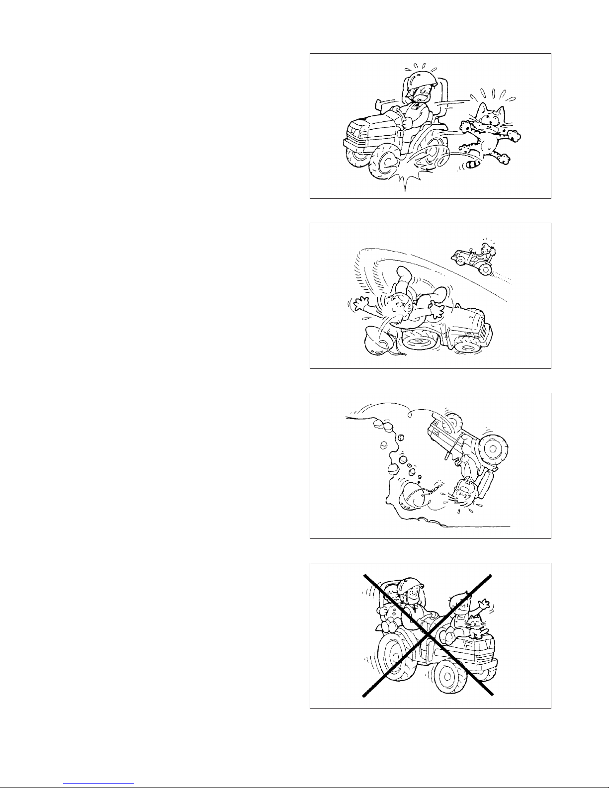
WHEN TRAVELLING
(1) When you travel on roads, ensure the differential lock
is off, or the tractor may turn over.
(2) Do not make sharp turns when operating at high
speed or for transportation as the tractor may turn
over.
(3) When operating on poor footing such as a rough
road, a slope, a road along a ditch or river, or undeveloped land, drive the tractor at low speeds and
operate it carefully.
(4) Do not make sharp turns on a slope. It may cause
turnover of the tractor.
When climbing up a hill, shift the speed change lever
to the most suitable speed. Start moving the tractor
as slowly as possible.
While climbing up a hill, never shift speeds along the
way.
When starting to move the tractor on an up-hill slope,
be sure that the front wheels do not lift up.
When going down a hill, drive the tractor at slower
speed that used to climb up the hill.
While going down a hill, never shift into neutral, and
never try to control the speed only with the brakes;
use the engine brake effectively.
(5) When traveling on a road where one or both shoul-
ders are slanted and which run along a ditch, look out
for softened shoulders especially when the ditch is full
of water and be careful not to let the machine slip
sideway.
(6) Never allow other persons to get on the machine or
the implement except when the machine or the implement is provided with a seat or a platform for persons
to sit or stand on, and only within the capacity specified.
Never allow persons to get on the implement while
traveling on roads.
(7) When parking the tractor, you have to park it on hard,
level ground and provide sufficient safety measures
by grounding the implement, removing the key, applying the parking brakes, and chocking the wheels
securely.
(8) Keep inflammable away from the engine during oper-
ation. Especially during stationary operation do not
operate the engine at high speeds so as not to set fire
to grass or straw with a heated exhaust pipe or
exhaust fumes.
(9) When you have to operate the tractor at night, make
sure of the location of the controls. If not, the tractor
might work unexpectedly by mistake.
FIG. 1-10
FIG. 1-11
FIG. 1-12
FIG. 1-13

TH4330,4290,4260
8
LOADING ONTO OR UNLOADING FROM A TRUCK
(1) When loading the tractor onto a truck or a trailer, turn
off the truck`s engine and apply the parking brakes to
the truck or the trailer.
Otherwise, the truck could move and the tractor falls
to the ground.
(2) Pay sufficient attention to the safety conditions
around the tractor and have it guided by someone to
assist the operation. Never allow other persons to
approach the tractor, especially in front of or behind it.
(3) When loading or unloading the machine on/off a
truck, set slip-proof ramps at the same angles and
drive the tractor straight at sufficiently slow speeds.
Loading the tractor in reverse travel and unloading it
in forward travel.
(4) Never depress the brake pedal during loading or
unloading operation, or the tractor may shift sideways, which may cause it to fall of the ramps.
(5) If the engine stalls unexpectedly on the ramps,
depress the brake pedal immediately and roll the tractor to the ground by manipulating the brake pedal.
Start the engine on the ground and try again.
(6) When the machine is loaded on the truck, stop the
engine, apply parking brakes, and withdraw the stator
key, chock the wheels, and rope it securely to the
truck. During transportation, do not make sharp turns
needlessly so as not to shift the loaded tractor.
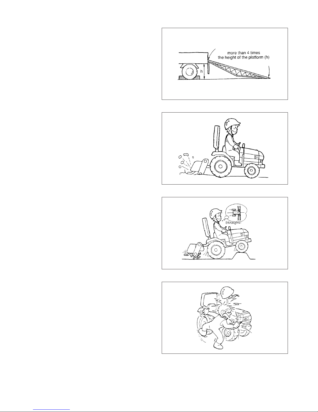
(7) Use ramps with the same or better specifications
mentioned below. When the machine is equipped
with attachments other than those included in the
specifications mentioned below, ask your ISEKI dealer for advice.
FIG. 1-14
FIG. 1-15
SAFETY
9
Specifications of the ramps
Length
More than 4 times the height of the platform of the truck
Width (effective width) more than 35cm
Capacity (one ramp) more than 1700kg
Ramps should have anti-skid surfaces
(8) Hook the ramps securely on the platform of the tractor
with the top of the ramp level with the platform.
(9) Always prepare for even the worst, by never allowing
other persons near the tractor.
(10) Drive the tractor carefully at the moment the trac-
tor moves from the ramps onto the platform, for it
changes angle abruptly.
DURING OPERATION
(1) During operation, never allow other persons in the
vicinity of the tractor, because the tractor itself or
flung pieces may cause injury.
(2) Pay attention to safety around the tractor to avoid
injury to bystanders or damage to property. Especially
when operating with other persons, use the horn to
warn them.
(3) When crossing a ditch or a levee or when passing
through soft land, drive the tractor slowly and straight
so that it dose not slip or turn over.
(4) Do not touch dangerous parts such as rotating parts,
moving parts, hot parts (muffler, radiator, or engine,
etc.), or electric parts (battery terminals and other live
parts), or you may be injured seriously.
(5) If you use a trailer, use a proper one which suits your
tractor. Using an improper trailer may cause serious
accidents. Never attempt to haul beyond the tractor`s
capacity. If you have a question, please consult ISEKI
dealer.
(6) When moving the machine toward an implement for
the purpose if installing the implement, never allow
any one to stand in between. When installing the
implement on the machine, be prepare to move away
promptly in the event of an emergency. The brakes
should be applied securely during installation.
(7) When moving the machine toward an implement for
the purpose if installing the implement, never allow
any one to stand in between. When installing the
implement on the machine, be prepare to move away
promptly in the event of an emergency. The brakes
should be applied securely during installation.
FIG. 1-16
FIG. 1-17
FIG. 1-18
FIG. 1-19

TH4330,4290,4260
10
INSPECTION AND MAINTENANCE
(1) When servicing the tractor or mounting or dismount-
ing an implement, place the tractor on level, hard
ground which is sufficiently illuminated, or unexpected
accidents may occur.
(2) When servicing the tractor, follow the instructions list-
ed below:
• Stop the engine.
• Apply parking brakes.
• Disengage all PTO.
• Place all gear shift levers in neutral.
• Remove the starter key.
• Lower the implement fully, if equipped.
If not, your hands or clothes may be caught or
sandwiched between.
(3) When servicing the tractor, use proper tools. Using
makeshift tools may lead to injuries or poor servicing,
which may result in unexpected accidents during
operation.
(4) The engine, muffler, radiator, etc. are very hot just
after operation, so wait until they cool down sufficiently to avoid burns.
(5) Never remove the radiator cap while the engine is hot
or running. Wait until the engine cools down and then
relieve the radiator pressure by releasing the radiator
cap. Carelessly pouring cooling water into the heated
radiator can cause serious damage to the radiator
and the engine. Careless removal of the radiator cap
can cause serious injury because of overheated
water vapour.
(6) Never fit unauthorized implements or attempt unau-
thorized modification.
(7) Be sure to reinstall the removed safety covers in
place as exposed dangerous parts may cause serious injury.
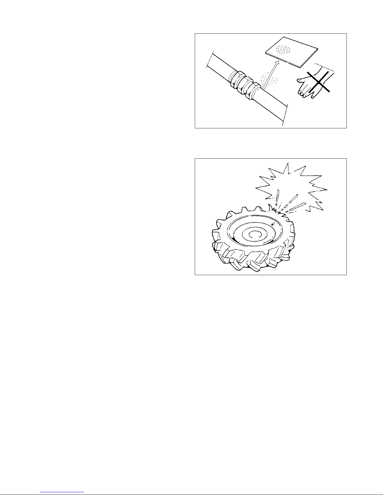
(8) Avoid high-pressure fluids. Escaping fluid under pres-
sure can penetrate the skin and cause serious injury,
so keep hands and body away from pin holes and
nozzles ejecting such fluids. Be sure to consult your
dealer about the hydraulic and fuel injection system
trouble.
When checking for leaks, use a piece of cardboard or
wood without fail. If any hydraulic fluid is injected accidentally into the skin, it must be removed within a few
hours by a doctor familiar with this type or injury.
FIG. 1-20
SAFETY
11
(9) When servicing wheels and tires, the tractor and/or
implement must be supported on suitable blocks or
stands. Not a hydraulic jack.
Do not attempt to service a tire unless you have the
proper equipment and experience to perform the job.
Have the work carried out by your ISEKI dealer or a
qualified repair service.
When seating tire beads onto rims, never exceed the
maximum inflation specifications specified on the tire.
Inflation beyond this maximum pressure may brake
the bead, or even the rim, with dangerous, explosive
force.
If tire have deep scratches, cuts or punctures, the
replaced by qualified personnel as soon as possible.
Wear suitable protective clothing, gloves, eye/face
protection.
STORAGE
(1) Never cover a hot machine just after operation with a
tarpaulin or the like, or the heated engine and related
parts may cause a fire.
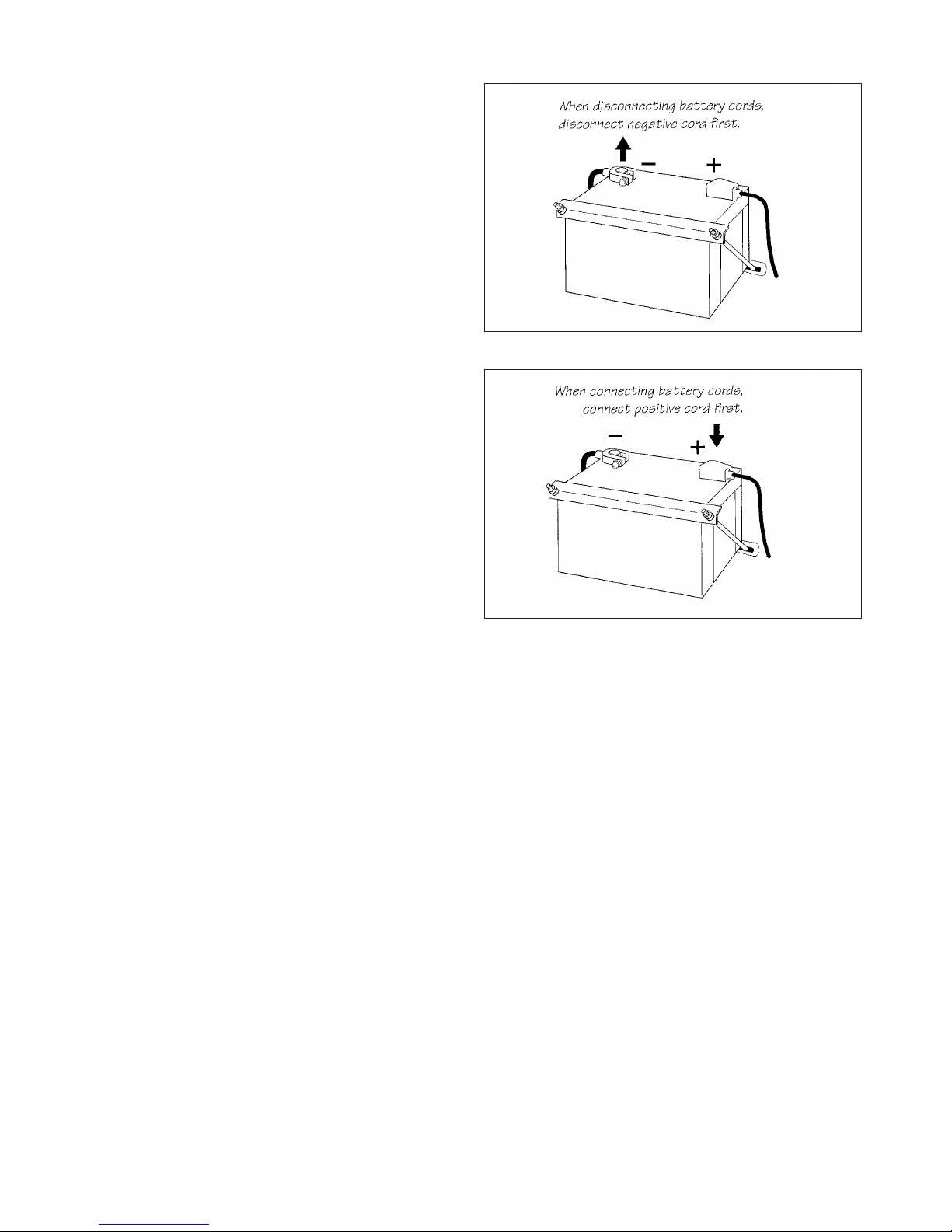
(2) Before storing the tractor for a long period of time,
disconnect the battery cables to prevent them, in
case they are gnawed by a rat, from causing a short
circuit, which may lead to a fire. When disconnecting
the cables, disconnect the negative (-) cable first.
(3) Safe storage of dangerous objects
• When storing dangerous implements, take appropriate safety measures to prevent accidents by
covering with tarpaulin.
• Store fuel in a safe place with caution signs such
as “PREVENT FIRE” or “INFLAMMABLE”.
• All inflammable must also be stored in a safe, fireresistant location.
FIG. 1-21
FIG. 1-22
TH4330,4290,4260
12
MAINTENANCE OF THE ELECTRIC SYSTEM
TO MAINTENACE ELECTRIC WIRING
(1) When servicing the electric wiring, stop the engine
without fail. Otherwise your hands or clothes may be
caught in or sandwiched between rotating parts.
(2) Before manipulating electric parts, be sure to discon-
nect the earth battery cable (-), or you may get an
electric shock or be injured by sparks.
(3) Loose electric terminals or connectors may not only
lower electrical performance but also cause short circuit or leakage of electricity, which may lead to a fire.
Promptly repair or replace damaged wiring.
(4) Remove chaff of dust from the battery, wiring, muffler,
or engine. Otherwise it could result a fire.
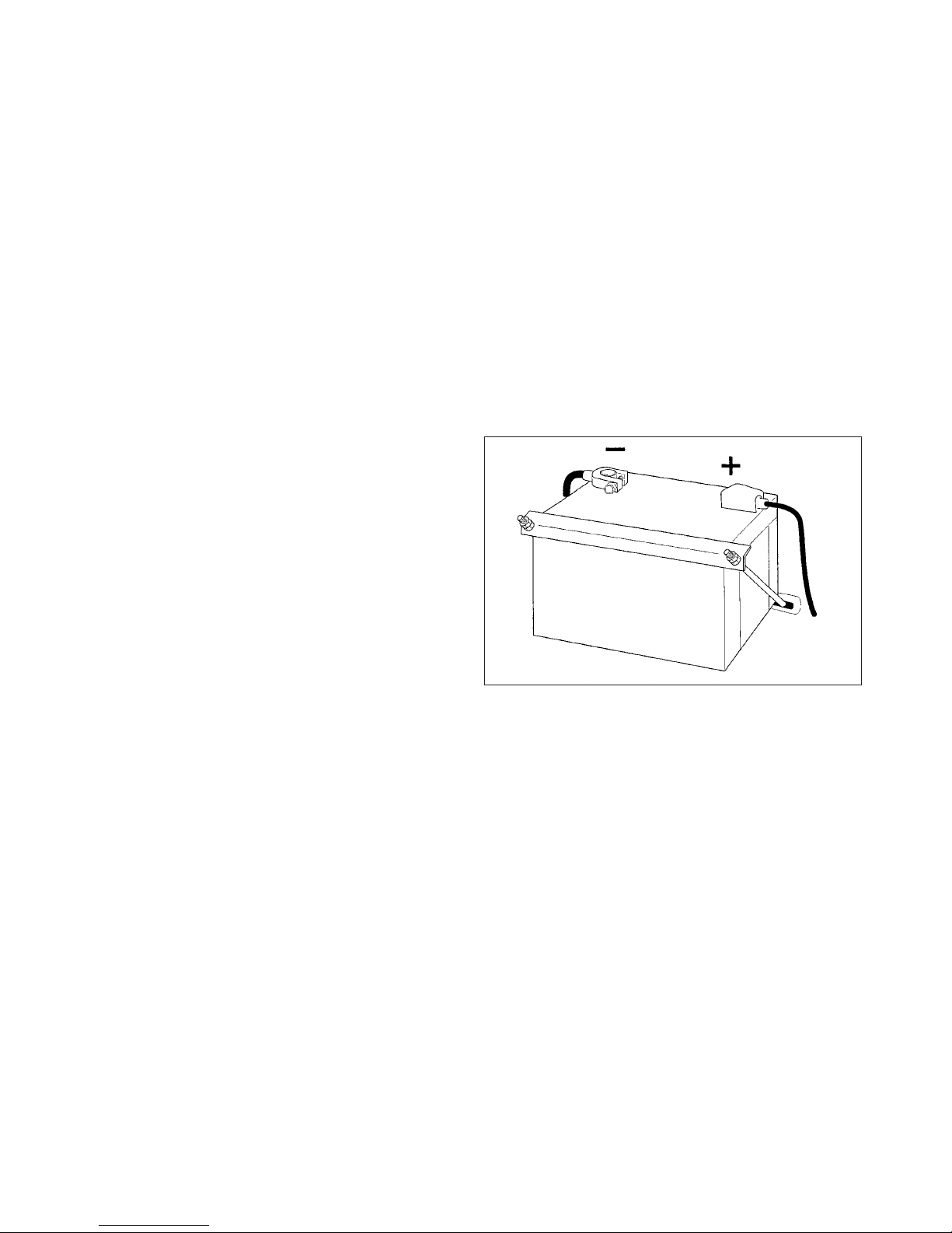
TO HANDLE THE BATTERY
(1) When working around the battery, avoid smoking.
The battery generates explosive hydrogen and oxy
gen gases when it is being charged.
Keep the battery away from sparks or open flames.
(2) The battery should be inspected before starting the
engine. Be careful not to touch the electrolyte when
removing the vent plugs. If the battery electrolyte
makes contact with the skin or clothing, wash it off
immediately with water and then consult a doctor.
(3) When replacing or inspecting the battery, stop the
engine and turn the main switch off, or electrical parts
may be damaged or unexpected accident may occur.
FIG. 1-23
SAFETY
13
When disconnecting the battery cables, disconnect the
earth cable (-) first without fail. When connecting the battery cables, connect the positive cable (+) first.
Disconnecting or connecting in wrong order may lead to a
short circuit or sparks.
TO HANDLE BOOSTER CABLES
When using booster cables, pay attention to the following
items for safe operation:
(1) Before connecting cables, remove the vent plugs.
This will lower the force in case of explosion.
(2) Before connecting cables, be sure to stop the engine.
Otherwise unexpected accidents may occur.
(3) Use booster cables with sufficient electrical capacity.
A cable of inadequate capacity will cause generation
of heat, which may lead to a fire.
SAFETY DECALS
The labels are stuck on the tractor. You should of course
read the safety instructions in the manual. But never fail
to read the labels on the machine as well.
• The labels should always be clearly seen, that is,
nothing should obscure them.
• When they have become dirty, wash them with
soap water and wipe off with soft cloth.
• If any of them are torn or lost, order new labels
from your dealer. Their codes are mentioned in
“SAFETY DECALS AND THEIR LOCATION”.
•A new label should be placed in the same place
where the old one was located.
• When sticking on a new label, clean the place to
enable the label to stick and squeeze out all air
bubbles trapped under it.
FIG. 1-24
FIG. 1-25
TH4330,4290,4260
14
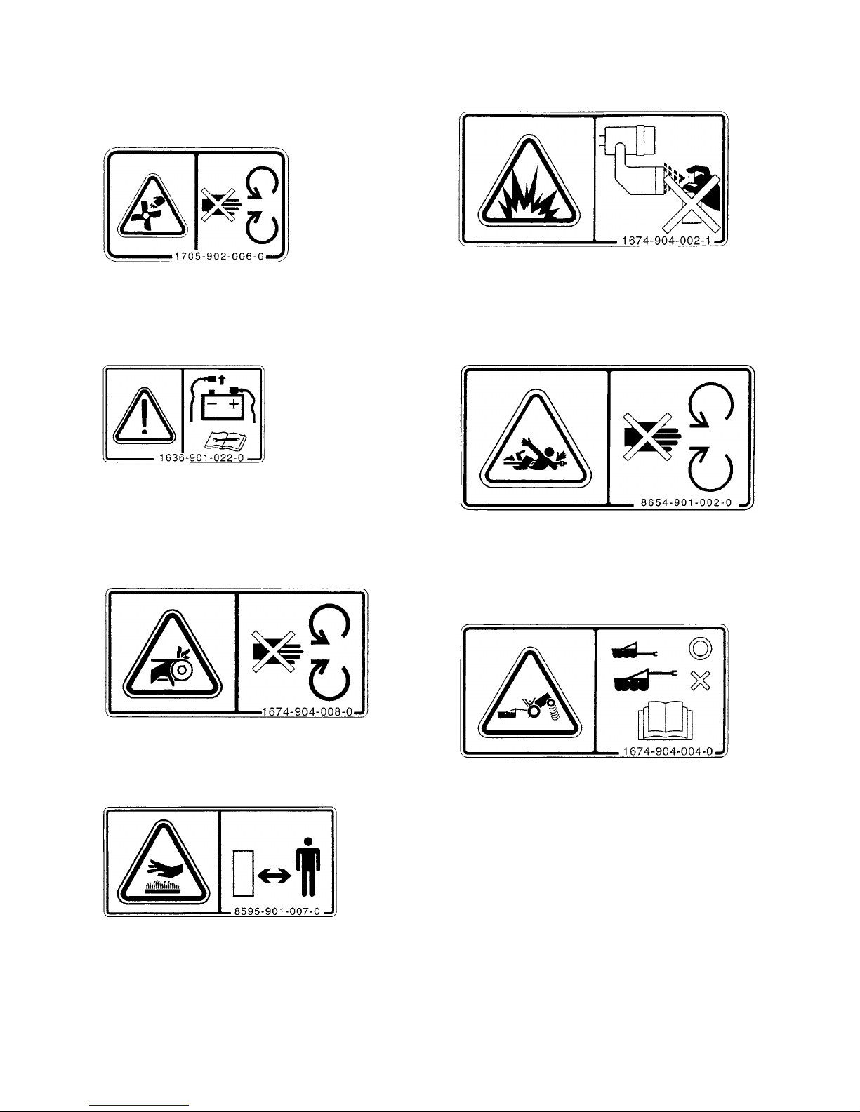
SAFETY DECALS AND THEIR LOCATIONS
(1) Fan warning label
(Code No. 1705-902-006-0)
WARNING: RISK OF ENTANGLEMENT
Stay clear of the fan while it is running.
(2) Battery disconnecting label
(Code No.1636-901-022-0)
WARNING: RISK OF ELECTRIC SHOCK
When disconnecting the battery, detach the negative
terminal first and attach the positive terminal first
when connecting the battery.
(3) Belt warning label
(Code No.1674-904-008-0)
WARNING: RISK OF ENTANGLEMENT
Stay clear of the belt while it is running.
(4) Hot part warning label
(Code No.8595-901-007-0)
WARNING: HOT SURFACES, RISK OF BURNS ON
HANDS AND FINGERS
Stay clear of the heated parts until they cool down
sufficiently.
(5) Ether label
(Code No.1674-904-002-1)
WARNING: RISK OF EXPLOSION
Ether or other starting fluid should never be used to
start engines equipped with glow plugs.
(6) PTO label
(Code No.8654-901-002-0)
WARNING: RISK OF ENTANGLEMENT
Stay clear of the PTO shaft while the engine is running.
(7) Trailer label
(Code No.1674-904-004-0)
WARNING: RISK OF OVERHEATING
The rear implement should be installed on the tractor
with an approved drawbar or by using the lower links
of the three point hitch. Use only weight not exceeding the designed capability of the tractor.
SAFETY
15
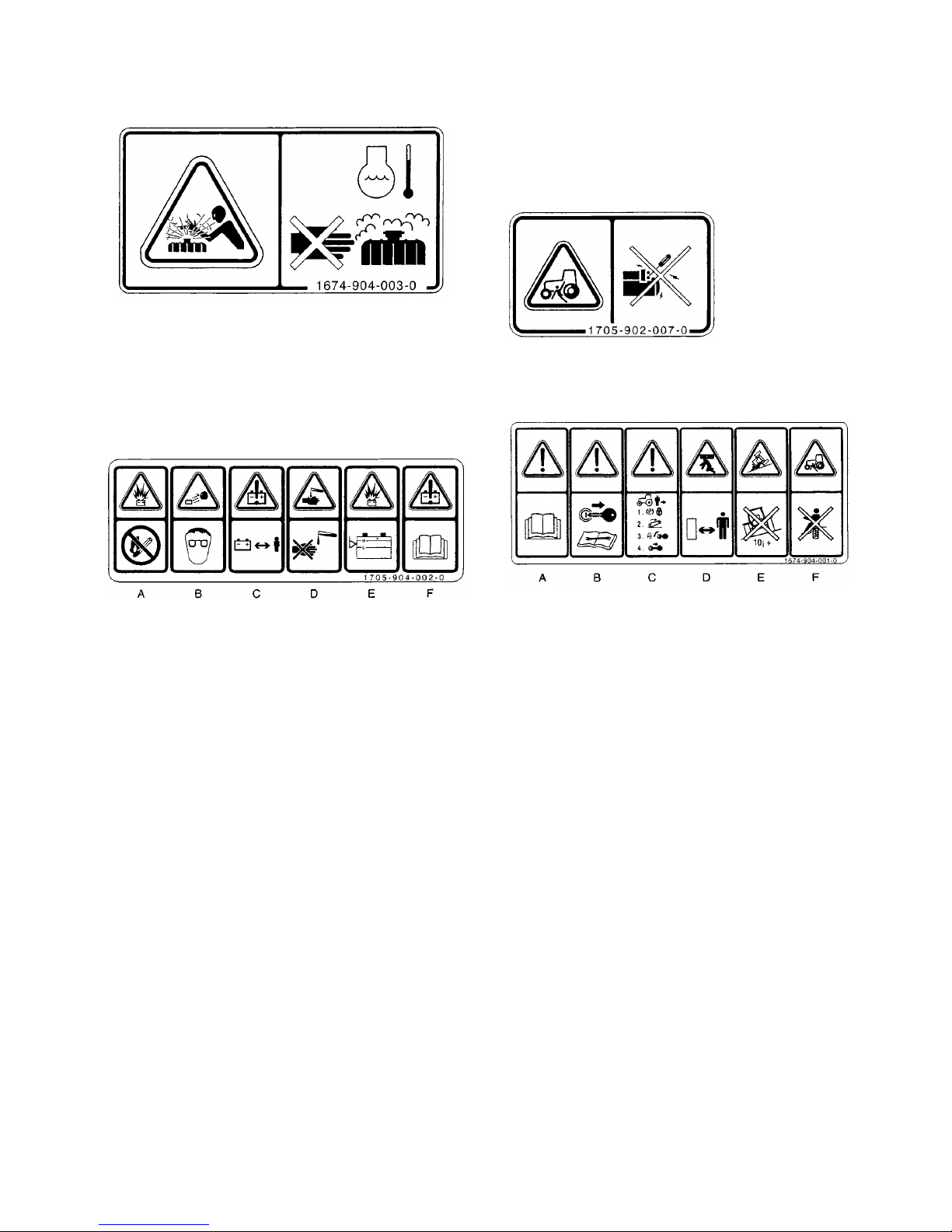
(8) Radiator label
(Code No.1674-904-003-0)
WARNING: HIGH PRESSURE STEAM AND HOT
WATER
Never remove the radiator cap during or just after
operation. The water in the radiator is very hot and
highly pressurized, which could cause burns.
(9) Battery label
(Code No.1705-904-002-0)
A. WARNING: RISK OF EXPLOSION
Keep away from sparks or flames, which could cause
explosion.
B. WARNING: WEAR AN EYE PROTECTION DEVICE
Battery electrolyte (euphoric acid) may cause blindness. Wear an eye protector to prevent contact with
the eyes.
C. WARNING: KEEP OUT OF REACH OF CHILDREN
D. WARNING: RISK OF BURNS
Battery electrolyte (sulphuric acid) may cause burns.
Avoid contact with skin or clothing. In case of an acci-
dent, flush affected part immediately with plenty of
water.
E. WARNING: RISK OF EXPLOSION
Never use the battery with the electrolyte surface
below the “LOWER” limit, or it may explode. Never
replenish exceeding “UPPER” limit or electrolyte may
leak out.
Maintenance free battery does not need to replenish
distill water.
D. WARNING: READ OPERATION MANUAL
Read the safety and operating instructions in the
operation manual before operating the tractor.
Take care of handling the battery.
Improper handling may lead to explosion.
Never short the poles.
Charge the battery in a well ventilated place.
(10) Starter warning label
(Code No.1705-902-007-0)
DANGER: RISK OF ELECTRIC SHOCK
Start the engine only from the seat using the key.
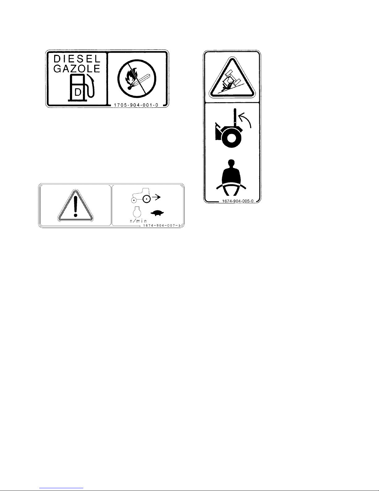
(11) Operation caution label
(Code No.1674-904-001-0)
A. WARNING: BEFORE OPERATION
Read the safety and operating instructions in the
operation manual before operating the tractor.
B. WARNING: BEFORE OPERATION
Read the safety and operating instructions in the
operation manual before operating the tractor.
C. WARNING: RISK OF ABRUPT MOVING
Before leaving the tractor unattached, apply the parking brake, lower the implement, turn off the engine
and remove the starter key to avoid unexpected moving of the tractor.
D. WARNING: RISK OF INJURY OR DAMAGE
Pay attention to safety around the machine to avoid
injury to bystanders or damage to properly.
E. WARNING: RISK OF OVERTURNING
Never operate the tractor on a slope of over 10
degrees, or it could overturn.
F. WARNING: RISK OF INJURY OR DAMAGE
Never allow other persons to get on the tractor or the
implement.
TH4330,4290,4260
16
(12) Fuel label
(Code No.1705-904-001-0)
DANGER: RISK OF EXPLOSION AND BURNS
Use only diesel fuel.
Before replenishing fuel, be sure to stop the engine
and wait until the engine and heated parts cool down
sufficiently. Keep sparks, open flames, etc. way from
the fuel tank.
No smoking!
(13) Reverse label
(Code No.1674-904-007-1)
Before moving tractor to reverse direction, be sure to
reduce engine speed.
(14) ROPS label
(Code No.1674-904-005-0)
WARNING: RISK OF INJURY
Keep the ROPS in the upright position and fasten the
seat belt at all times. Do not jump from the seat if the
tractor starts to overturn, or you could be crushed
under the tractor. The ROPS should usually be kept
in the upright position during operation.
However, when the ROPS has to be lowered, do not
wear the seat belt and operate the tractor with
extreme caution.
Do not operate the tractor with a damaged or modified ROPS.
SAFETY
17
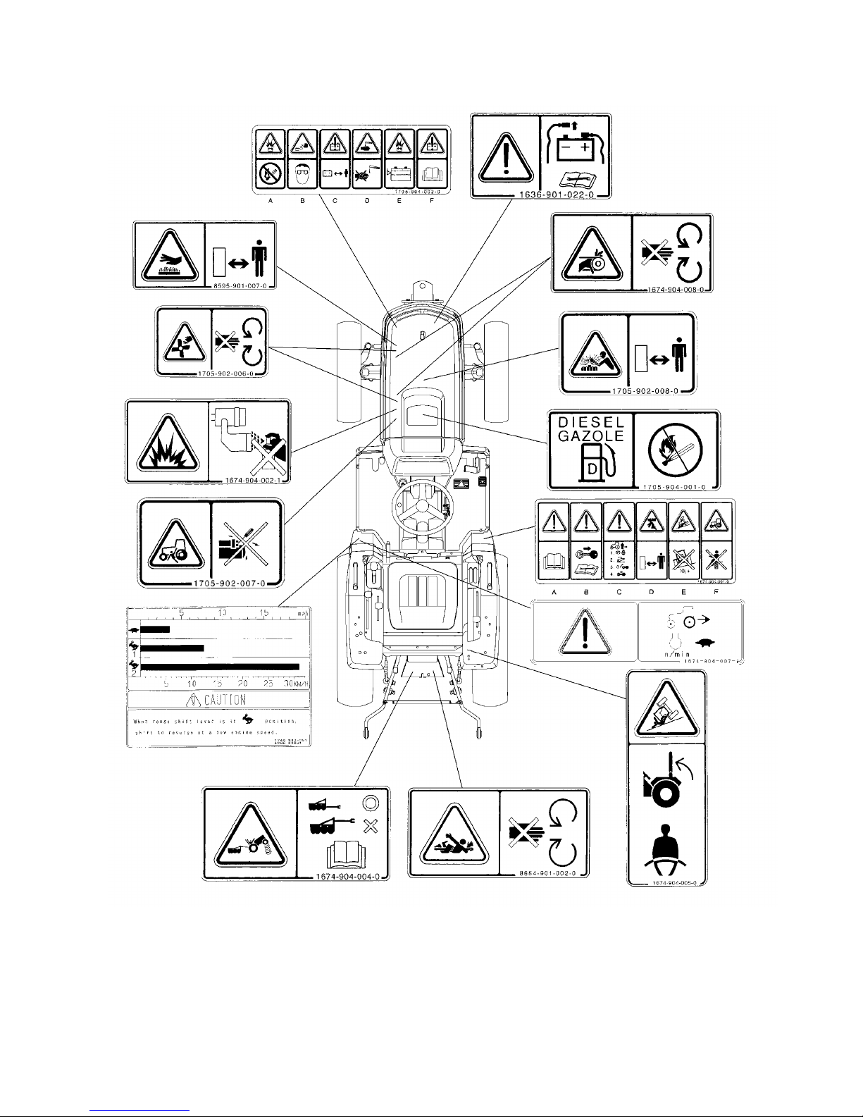
LOCATION OF SAFETY DECALS
Location of all instruction decals provided as a reference.
Replace any decals that are damaged, missing or are not
readable. Consult your dealer.

TH4330,4290,4260 INTRODUCTION
18
The information in this publication describes the operation, maintenance and servicing of the TH4330, 4290 and 4260
Tractors. Every effort has been made to provide correct and concise information to you, the operator, as available at
date of book publication. Your ISEKI Dealer is available should items in this book or details of your machine not be
understood.
This book is supplied with each machine to familiarize the operator with proper instructions needed for operation and
maintenance. Studying and adhering to these instructions will insure optimum machine performance and ·longevity. A
machine that is maintained properly and operated in the intended manner will provide greater dividends than one that
is neglected and/or operated in manner other than as intended. Design and servicing of this machine has been kept as
simple as possible to permit maintenance operations to be carried out with tools normally available.
This book should be thoroughly read and understood prior to operation of this machine. Inexperienced operators
should study contents of this publication and receive instruction from an experienced operator when possible. Your
ISEKI Dealer can also assist in areas concerning machine operation and provide details concerning safe operation. it
is suggested that this booklet be kept readily accessible, preferably with the machine, for future reference if questions
or concerns arise. If the original book should become damaged, consult your Dealer in regards to acquiring a replacement.
Customers are strongly advised to use an official
ISEKI Dealer in connection with any service problems and adjustments that may occur. The ISEKI Dealer network is
specially trained and equipped for all service work and to advise customers on specific applications of the Tractor in
local conditions.
CAUTION: In some of the illustrations used in this Operator Instruction Book, panels or guards may
have been removed for clarity. Never operate the Tractor with these panels and guards removed. If the
removal of a shield is necessary to make a repair, it MUST be replaced before operation.
CAUTION: READ THIS BOOK IN ITS ENTIRETY PRIOR TO OPERATING MACHINE.
Use only ISEKI parts for repairs and/or replacement.
INTRODUCTION
TRACTOR IDENTIFICATION
19
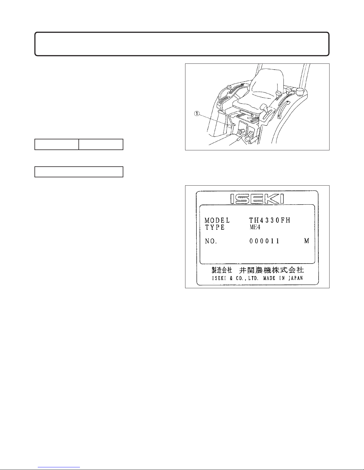
MODEL/SERIAL NUMBERS
Each Tractor is identified by means of Tractor model and
serial numbers. As a further identification, engine and
chassis are provided with identification numbers.
To ensure prompt, efficient service when ordering parts
or requesting repairs from authorized Dealer, record
these numbers in spaces provided.
TRACTOR MODEL
TRACTOR SERIAL NUMBER
FIGS. 3-1 & 3-2: Tractor identification plate, 1, located
below operator's seat on right-hand side of fender.
Contains model number, machine series number and
weight in addition to Tractor serial number.
TRACTOR IDENTIFICATION
FIG. 3-1
FIG. 3-2
TH4330,4290,4260
20
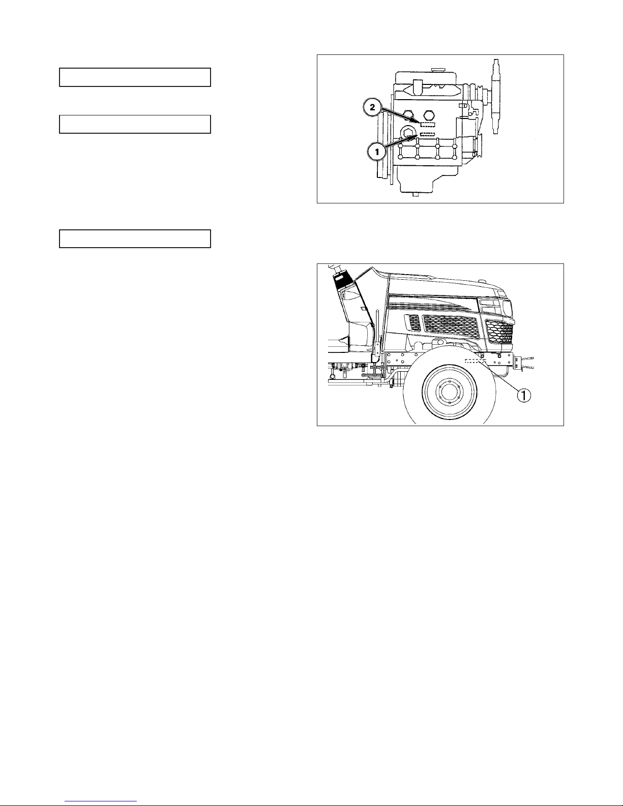
ENGINE MODEL NUMBER
ENGINE SERIAL NUMBER
FIG. 3-3: Engine model number, 1, is cast on right side of
engine block, below the injection pump.
Engine serial number, 2, is stamped into cylinder block,
below engine model number.
CHASSIS NUMBER
FIG. 3-4: Chassis number, 1, is stamped in right side of
front frame.
NOTE: Reference to left-hand and right-hand, used
throughout this book, refers to the position when
seated in operator's seat and facing forward
FIG. 3-3
FIG. 3-4
TRACTOR IDENTIFICATION
21
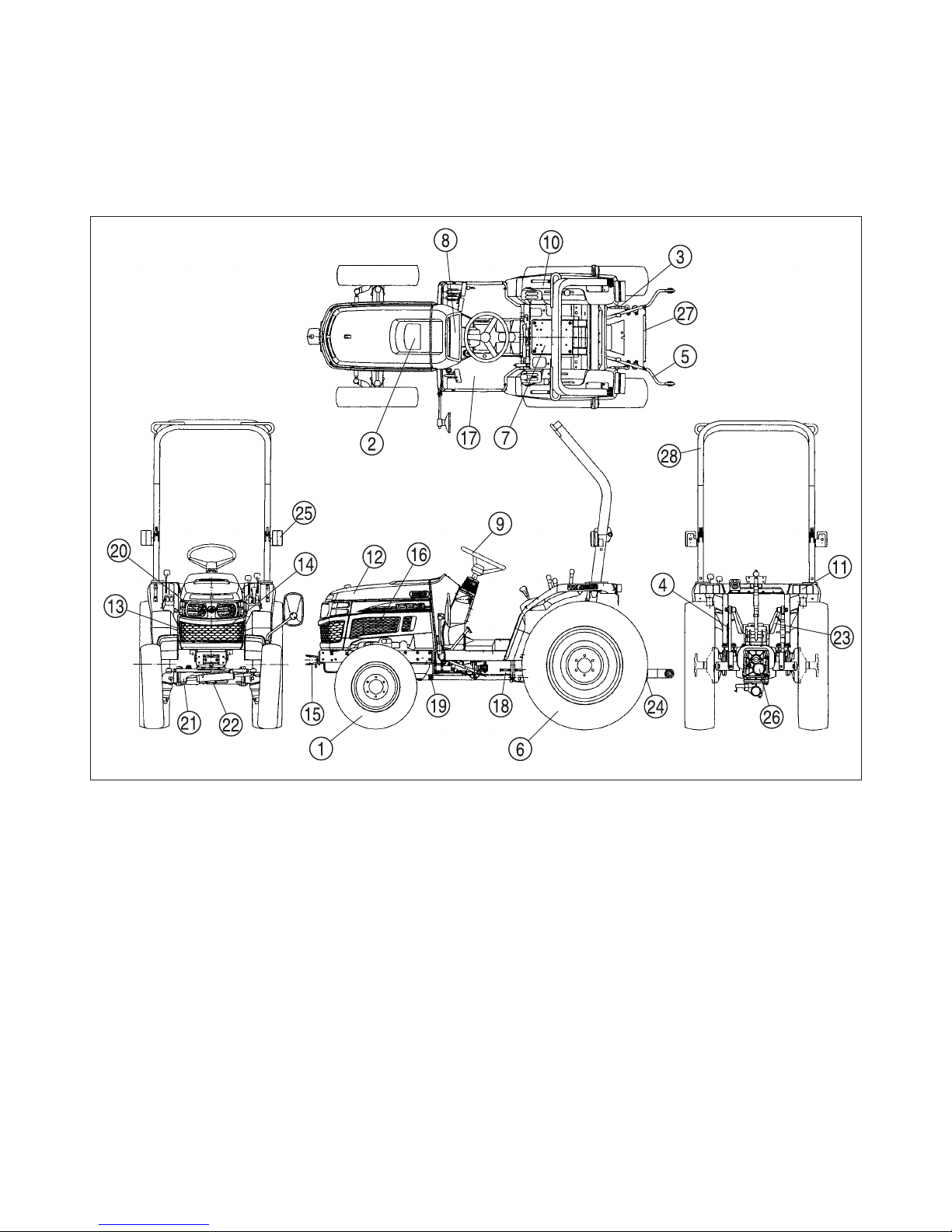
MAJOR COMPONENTS
FIG. 3-5:
Identification and terminology of major components, as given in this book, are as follows;
1. Front Wheels
2. Fuel Tank Filler
3. Stabilizer
4. Lift Rod
5. Lower Link
6. Rear Wheels
7. Operator’s Seat
8. Instrument Panel
9. Steering Wheel
10. Fender
11. Reflector / Tail Light
12. Hood
13. Front Grille
14. Battery
15. Front Hitch
16. Engine
17. Foot Step
18. Transmission
19. Front Wheel- Drive Shaft (4WD)
20. Headlight
21. Front Axle
22. Front Axle Pivot
23. Lift Arm
24. Drawbar
25. Turn / Hazard Light
26. Center Housing
27. Lower Link Spring
28.
Roll-Over Protective Structure (ROPS)
TH4330,4290,4260
22
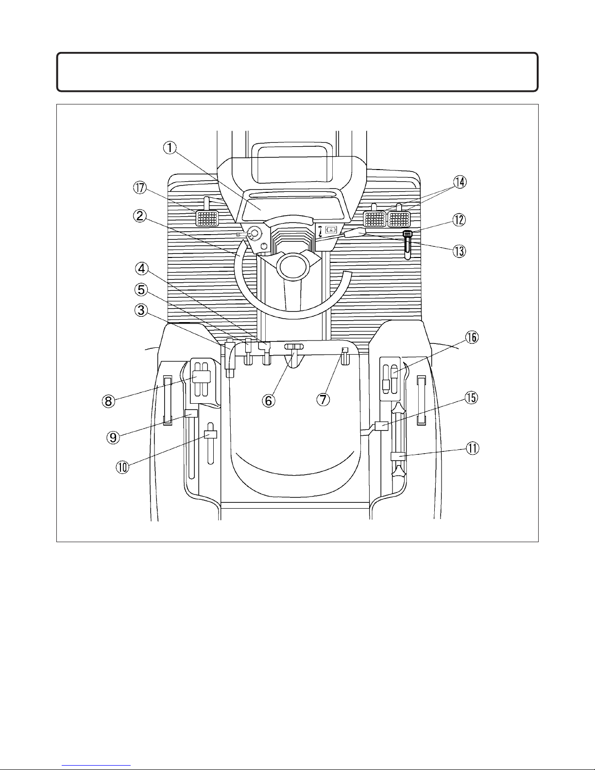
1. Instrument Panel
2. Steering Wheel
3. Parking Brake
4. Mid Power Take-Off (PTO) Selector Lever
5. Front Wheel Drive (4WD) Shift Lever
6. Slow Lowering Control Knob
7. Differential Lock Pedal
8. Main Gear shift Lever
9. Range Gear Shift Lever
10. Rear Power Take-Off (PTO) Selector Lever
11. Three-Point Hitch Position Control Lever
12. Foot Throttle Pedal
13. Hand Throttle Lever
14. Brake Pedals
15. Draft Control Lever (Accessory)
16. Auxiliary Hydraulic Valve Controls (Accessory)
17. Clutch Pedal
INSTRUMENTS & CONTROLS
FIG. 4-1: General layout and location of controls within operator’s area on Tractor. Specific use of these controls is
given later in this section and also in “Operation” section of this book:
FIG. 4-1 (Mechanical Transmission)
INSTRUMENTS & CONTROLS
23
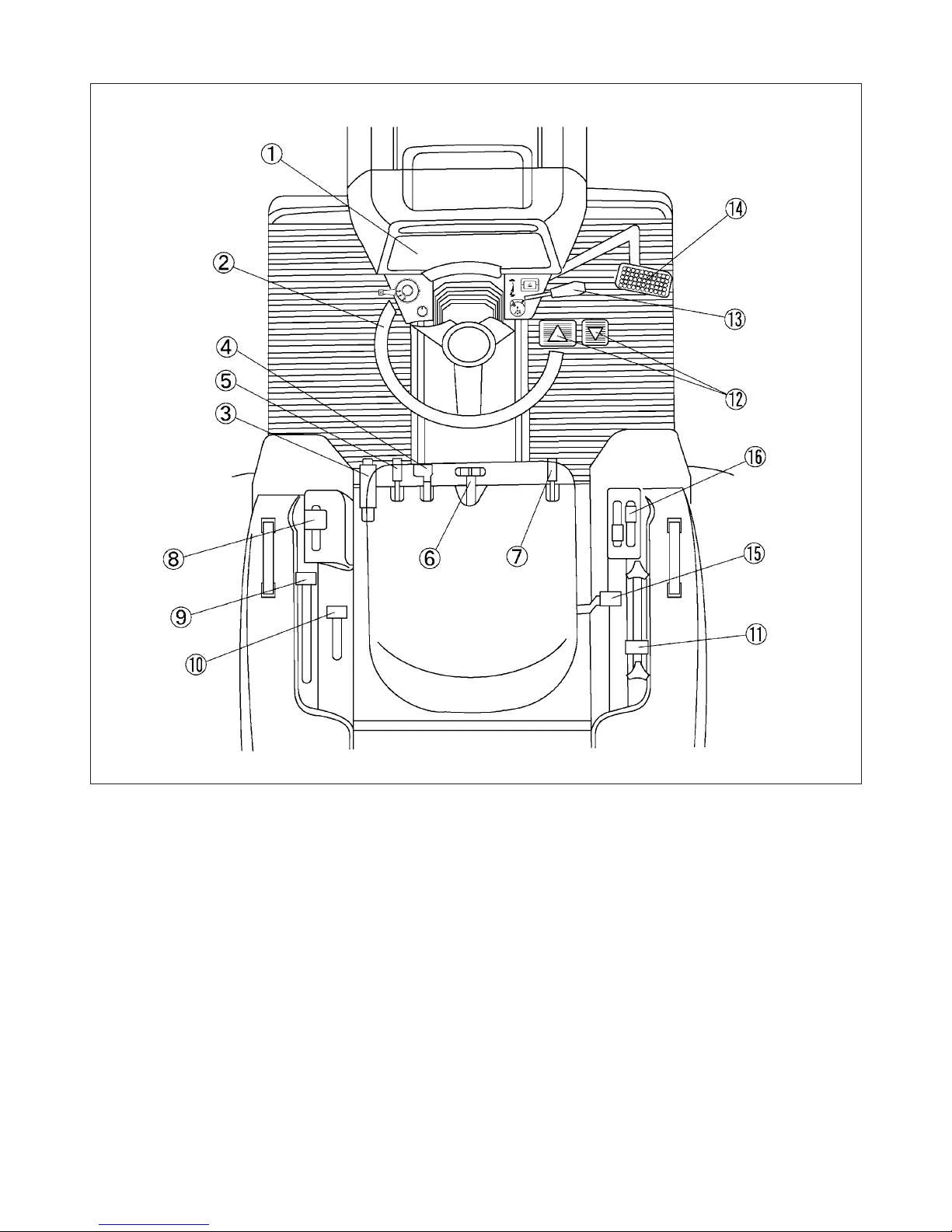
1. Instrument Panel
2. Steering Wheel
3. Parking Brake
4. Mid Power Take-Off (PTO) Selector Lever
5. Front Wheel Drive (4WD) Shift Lever
6. Slow Lowering Control Knob
7. Differential Lock Lever
8. Hydrostatic Control Lever (TH4330/4290)
9. Range Gear Shift Lever
10. Rear Power Take-Off (PTO) Selector Lever
11. Three-Point Hitch Position Control Lever
12. Hydro Forward Reverse Pedal
13. Hand Throttle Lever
14. Brake Pedal
15. Draft Control Lever (Accessory)
16. Auxiliary Hydraulic Valve Controls (Accessory)
FIG. 4-2: General layout and location of controls within operator’s area on Tractor. Specific use of these controls is
given later in this section and also in “Operation” section of this book:
FIG. 4-2 (Hydrostatic Transmission)
TH4330,4290,4260
24
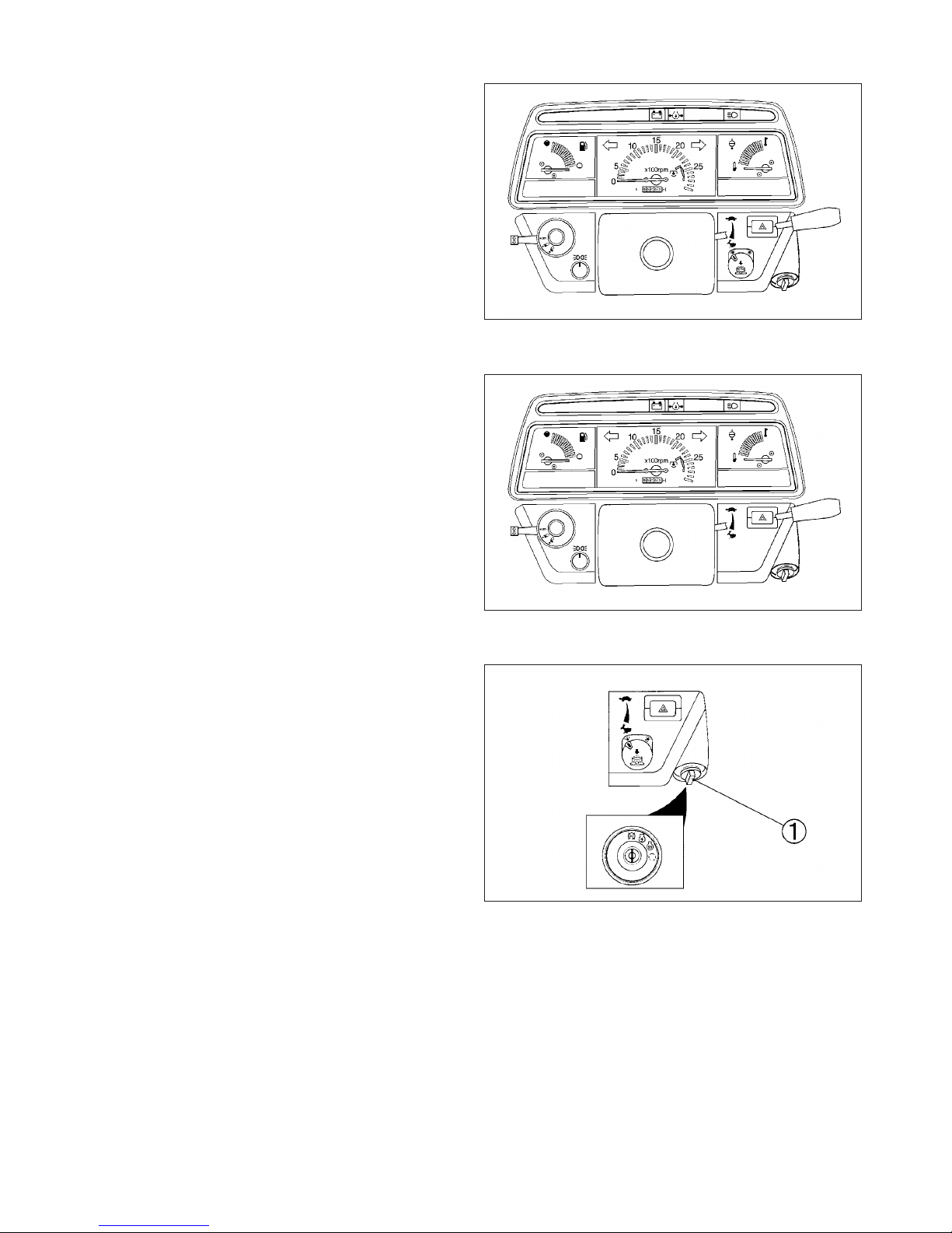
INSTRUMENT PANEL
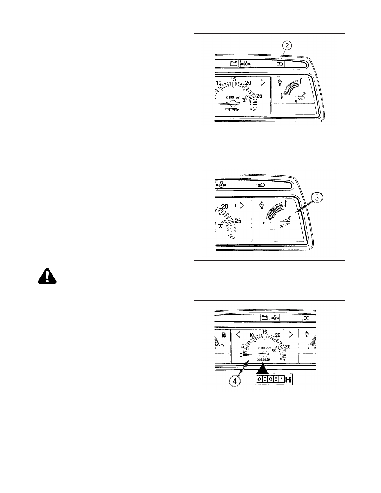
FIGS. 4-3, 4-4: Arrangement of gauges, control switches
and indicators located in instrument panel. Items are
detailed in the descriptions that follow:
NOTE: Instrumental panel and switches may vary from
those shown.
Electric Fuel Shut-Off
Turning main switch to off stop will stop engine. This
Tractor is equipped with electric engine shut-off system,
consisting of a solenoid and timer, to shut off fuel and
stop engine.
When main switch is turned off, timer activates solenoid
to shut-off fuel and hold it off for ten seconds. After ten
seconds, solenoid returns to “fuel on” position.
Selecting main switch to “ON” will override timer to turn
fuel on and allow engine to be immediately restarted.
Main Switch
FIG. 4-5: Main Switch, 1, has the four following positions:
p OFF Engine and all electrical circuits off.
Key can be removed.
O ON Power supplied to all circuits. Normal
operating position.
G GLOW Energizes glow plugs to preheat the com
bustion chambers and assist
starting.
f START Starter activated. This position
spring-located to "ON"
NOTE: The main switch must be turned to "ON" before
any circuits will operate. PTO switch must be
turn off before engine can be started.
This Tractor is equipped with an electric fuel
shut-off. When main switch, 1, is turned to “start”,
“on”, or “glow” position and range gear shift lever
is placed in neutral solenoid moves the fuel linkage on injection pump to run position to start
engine. When main switch is turned to “off”
(stop), solenoid moves fuel linkage to off position
to stop engine.
IMPORTANT: When the main switch is selected to
"GLOW" position, the engine combustion
chambers will be preheated and allow a
cold engine to be started after several
seconds.
FIG. 4-3 (Hydrostatic Transmission)
FIG. 4-4 (Mechanical Transmission)
FIG. 4-5
INSTRUMENTS & CONTROLS
25
Indicator Light Strip
FIG. 4-6: Indicator light strip, 2, contains several warning
lights to monitor certain functions. Currently used positions (from left to right) are:
Battery Charge - Lights up when main switch is turned
"ON" and will go out after engine starts, to indicate battery is being charged.
Engine Oil Pressure - Lights up if engine oil pressure is
low. If the light comes on while the engine is running, shut
off the engine immediately and investigate the cause.
Main (High) Beam – Illuminates when head lamps in
front grill are selected to high beam position by light
switch.
Coolant Temperature Gauge
FIG. 4-7: Gauge, 3, indicates engine coolant temperature
when main switch is selected to “ON”.
Cold - (Extreme left) Shows too cool temperature for
severe work. Allow to warm (needle in mid position)
before applying heavy load.
Hot – (Extreme right) Indicates over-heating (red area on
gauge). Reduce engine speed to idle, allow to run at no
load several minutes, shut off engine and investigate
cause (refer to “Troubleshooting”).
CAUTION: Do not service hot engine. Allow
to completely cool before servicing or removing radiator cap.
Tachometer
FIG. 4-8: Scale on gauge, 4, indicates engine speed in
crankshaft revolutions per minute (rpm). Index is also provided to show rear PTO speed of 540 approximately 2300
engine rpm.
Hour meter in center of gauge indicates engine and tractor use to assist in maintenance intervals. The extreme
right digit indicated 1/10 hour increments.
FIG. 4-6
FIG. 4-7
FIG. 4-8

TH4330,4290,4260
26
Fuel Gauge
FIG. 4-9: Gauge, 5, indicates level of diesel fuel in fuel
tank when main switch is “ON”.
NOTE: Use only clean diesel fuel and clean area to pre-
vent dirt/water entry into fuel tank when refilling.
DO NOT run out of fuel as bleeding air from the
system will be required. Keep fuel tank full minimize condensation.
CAUTION: DO NOT refill fuel tank with engine
running or hot. Allow cooling period. DO NOT
smoke near fuel tank. Clean up any spilled
fuel.
Parking Lamp Switch
FIG. 4-10: When the parking lamp switch, 6, is turned,
small lamps are lighted up.
Horn & Light & Turn Switch
FIG. 4-11: With main switch “ON”:
Horn Switch, 7 – Horn sill sound when center switch but-
ton is depressed.
Light Switch, 8 – Is a rotary switch with three operating
positions:
OFF – Fully counterclockwise. All lights off.
1st – Main (high) beam headlamps and rear tail lights.
2nd – Low beam headlamps and rear red tail lights.
NOTE: When high beam is selected (1st position), light
indicator light strip will come on.
Turn Switch, 9 – Operate switch handle in direction
Tractor is to be turned. The appropriate flashing amber
warning light (fender-mounted) will operate as turn signal.
Return switch to center position to cancel.
NOTE: Turn lights will not self-cancel. Select turn/hazard
lights switch to center position completing turn.
Hazard Signal Switch
FIG. 4-12: Push down switch, 10, to turn on hazard lights.
Both flashing amber warning lights will operate at the
same time.
CAUTION: Hazard lights must be used any
time Tractor is driven on public roadway.
Consult local agencies for other marking
requirements.
FIG. 4-9
FIG. 4-10
FIG. 4-11
FIG. 4-12
INSTRUMENTS & CONTROLS
27
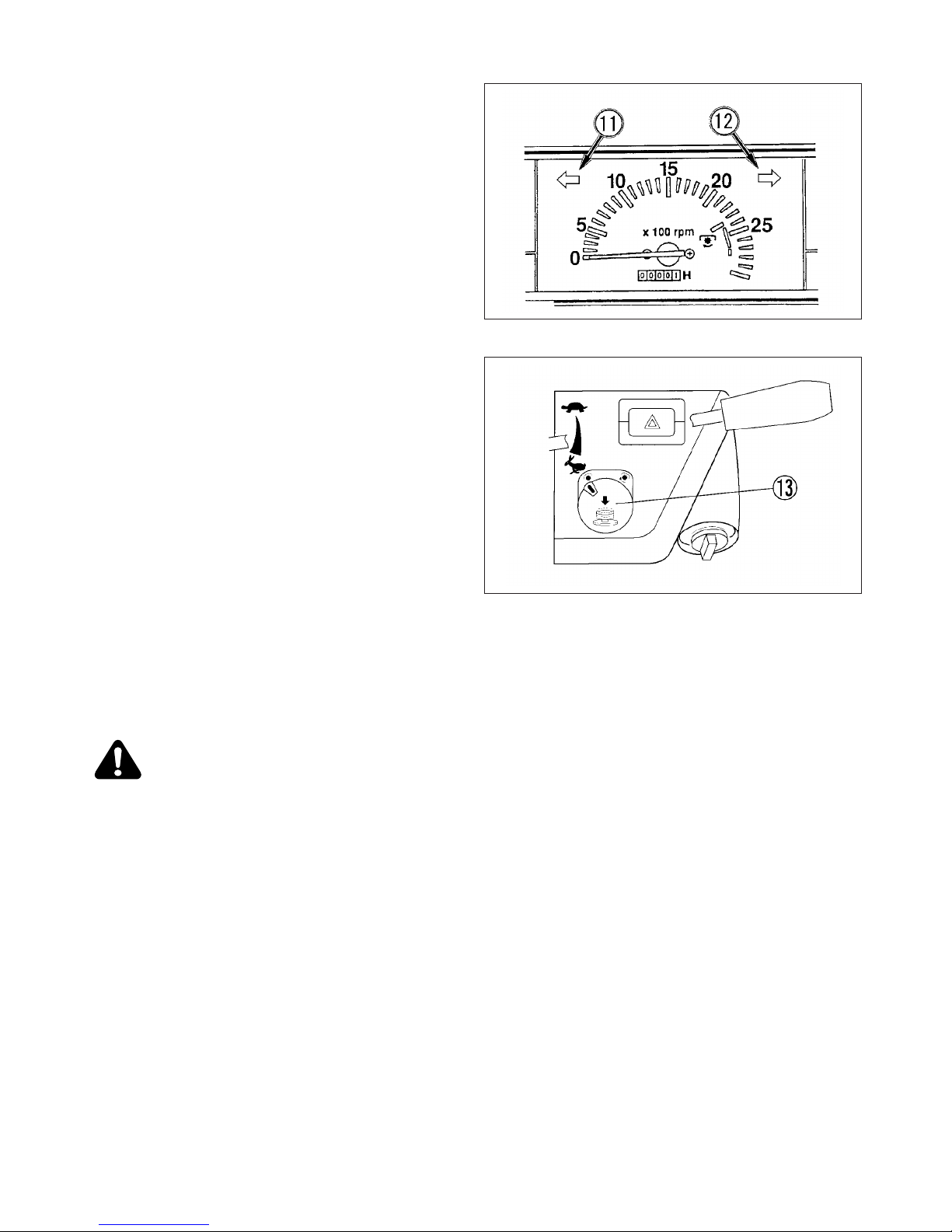
FIG. 4-13: Turn / hazard indicator lights, 11 and 12, will
operate with fender-mounted warning lights. This provides operator with easy indication of warning lights
selection.
NOTE: Turn lights will not self-cancel. Select turn / haz-
ard lights switch to center position after completing turn.
Power Take-Off (PTO) Switch (Hydrostatic transmission)
FIG. 4-14: A push & turn type safety switch, 13, is used to
engage and disengage the PTO drive system.
The switch must first be pushed in and then rotated
clockwise to engage PTO.
The switch is pushed to disengage PTO.
IMPORTANT: PTO switch is equipped with a lock-out to
prevent accidental engagement of PTO
on switch to unlock AND THEN, rotate
switch clockwise to ON position. DO NOT
FORCE SWITCH.
NOTE: PTO switch, 1, must be used in conjunction with
rear and mid PTO selector lever, to left and
under operator’s seat, when rear and mid PTO
used. Refer to “Operation” section for complete
details.
When PTO control switch is “ON”, the engine
cannot be started. Always switch off PTO and
place range gear shift lever in neutral to start
engine.
WARNING: Always shut off PTO and shut off
Tractor engine before servicing PTO driven
implement. Allow movement and motion to
stop before leaving operator’s seat.
FIG. 4-13
FIG. 4-14
TH4330,4290,4260
28
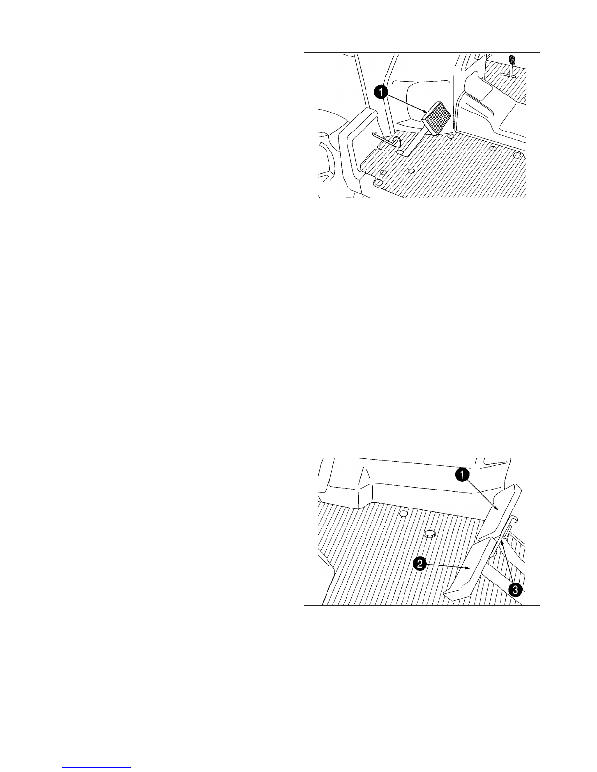
MAIN CLUTCH PEDAL
Dual clutch-TH4290/4260 with a mechanical transmission
FIG. 4-15: These tractors are equipped with a two stage
clutch.
Depressing the pedal (1) will reveal two distinct areas of
operation made apparent by changes in pedal effort.
Depressing pedal through its first stage will disconnect
transmission drive and allow motion of tractor to be
stopped.
The power take-off (PTO) will continue to operate.
Additional and final downward movement of the clutch
pedal will disengage the engine from the PTO drive while
the pedal is depressed.
Releasing the clutch pedal will re-engage the PTO drive
first, which allows the PTO driven machine to get up to
speed, and then with transmission in gear, forward travel
will begin as the second stage clutch is released.
Note:
•Clutch pedal should be depressed quickly to
prevent abnormal wear.
Clutch pedal should be raised smoothly to prevent sudden movement.
DO NOT rest your foot on the clutch pedal
except when operating the clutch.
Important: Clutch pedal free-play adjustment should
be adjusted correctly. Consult "mainte
nance" section.
BRAKES
Brake Pedals (Mechanical Transmission)
FIG. 4-16: Inner brake pedal (1) and outer brake pedal
(2) independently control the respective left and right
wheel brakes, to assist in turning.
During tractor transport or high speed operation, the
brake pedals must be latched together using interlocking
plate (3)
FIG. 4-15
FIG. 4-16
INSTRUMENTS & CONTROLS
29
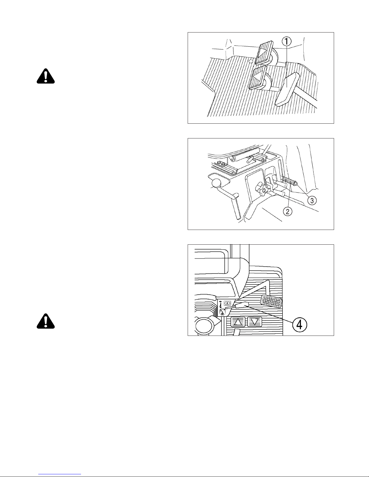
Brake Pedal (Hydrostatic Transmission)
FIG. 4-17: Brake pedal, 1, control the left and right wheel
brakes at the same time.
CAUTION: For towing safety, the towed
equipment, when fully loaded, should not
exceed 1.5 times weight of towing unit.
Parking Brake
FIG. 4-18: To engage parking brakes, pull upward on
parking brake lever, 2, to lock brakes in applied position.
To disengage parking brakes, push in on release button,
3, and lower lever to the released position.
IMPORTANT: Always disengage the brake before driving
the tractor to prevent abnormal brake
wear.
ENGINE SPEED CONTROL
Throttle Lever
FIG. 4-19: Throttle lever, 4, controls engine speed and
will remain in position selected by the operator.
Idling speed: With hand lever is forward, engine will idle.
High speed: Engine speed increases as lever is pulled
progressively rearward.
(Hydrostatic Transmisson)
These tractor is equipped with Auto throttle system, it
raises up engine speed by depressing forward direction
HST pedal. Whenever it would be used, tractor does not
load any implements or trailer.
When tractor is operated with implements or trailer, set
rated engine speed by hand throttle lever.
CAUTION: Always select engine speed to
ensure safe operation. Reduce speed prior to
turning or backing Tractor.
FIG. 4-17
FIG. 4-18
FIG. 4-19
 Loading...