

Iseki SXG19H-UGE, SXG22H-UGE, SXG22H-UE, SXG19H-UE Operation Manual

ISEKI LAWN MOWERS
1
Thank you very much for purchasing an ISEKI lawn mower.
This operator's manual provides the information necessary for operating and maintaining the lawn
mower safely and properly.
SAFETY-DANGER,WARNING AND CAUTION
Every time you see the words and symbols shown below in the manual and on the safety
decals, you must take note of their instructions and warning.
DANGER: This symbol together with the words DANGER indicates an imminently hazadous situation that, if not avoided, will result in VERY SERIOUS INJURY OR EVEN DEATH.
WARNING: This symbol together with the word WARNING indicates a potentially hazardous situation that, if not avoided, could result in SERIOUS INJURY OR EVEN DEATH.
CAUTION: This symbol together with the word CAUTION is used to indicate a potentially hazardous
situation that,if not avoided,may result in MINOR INJURY.
IMPORTANT: The word IMPORTANT is used to provide instructions or advice in order to let
the lawn mower provide the optimum performance.
NOTE: The word NOTE is used to indicate points of particular interest for more efficient and
convenient repair or operation.
SAFETY INSTRUCTIONS: Essential items which you should observe while operating the
lawn mower
TECHNICAL INSTRUCTION: Items which are necessary to operate, adjust,and service the
lawn mower properly
Before starting to operate the lawn mower for the first time, you should read this operation manual thoroughly and carefully until you are sufficiently familiar with the operation of the lawn mower in order to do
jobs safely and properly. You are advised to refer to it from time to time to refresh your understanding of the
lawn mower.
The manual should be kept in a handy place so you can refer to it when required.
The parts employed in this lawn mower may be modified without notice for better performance and
quality and for safety purposes, which may lead to some inconsistency found on your lawn mower with the
contents of this manual.
The lawn mower is designed to be used on well-kept lawns. Using the lawn mower in other places is not
authorized. Besides, the manufacturer will not pay for any damage caused by unauthorized use and the risk is
only borne by the user. Proper use of the lawn mower also implies that the user follows the operational,
adjusting,and servicing instructions indicated in the operation manual.
When you have any question about your lawn mower, you are always welcome to ask your dealers.
INTRODUCTION

SXG
2
INTRODUCTION ............................................................................................................................ 1
I. FOR SAFE OPERATION ............................................................................................................ 5
1. HOW TO BE A SAFE OPERATOR........................................................................................ 5
2. BEFORE STARTING THE LAWN MOWER.......................................................................... 6
3. OPERATION OF THE LAWN MOWER................................................................................. 7
4. OPERATION ON A SLOPE ................................................................................................... 8
5. DRIVING ON PUBLIC ROADS: ............................................................................................ 8
6. LOADING ONTO OR UNLOADING FROM A TRUCK:......................................................... 8
7. WHEN FILLING WITH FUEL: ............................................................................................... 9
8. MOUNTING AND DISMOUNTING OF THE MOWER DRIVE SHAFT.................................. 10
9. LAWN MOWER MAINTENANCE:......................................................................................... 10
10. ELECTRICAL SYSTEM ........................................................................................................ 11
11. TYRES AND WHEELS.......................................................................................................... 12
12. BEFORE STORING THE LAWN MOWER............................................................................ 12
13. LONG TERM STORAGE ...................................................................................................... 13
14. Caution labels & their positions............................................................................................. 14
II. WARRANTY AND AFTER-SAFE CARE ................................................................................... 21
III. SPECIFICATIONS..................................................................................................................... 23
LAWN MOWERS
IV. NAMES OF MAJOR COMPONENTS....................................................................................... 25
V. CONTROLS AND METERS....................................................................................................... 26
1. CONTROL PANEL ................................................................................................................ 26
1.1. STARTER SWITCH.......................................................................................................... 27
1.2. THROTTLE LEVER ......................................................................................................... 27
1.3. MONITOR LAMP ARRAY................................................................................................. 27
1.4. PTO LEVER ..................................................................................................................... 28
1.5. HOURMETER .................................................................................................................. 28
1.6. Headlight switch (UE TYPE) ............................................................................................ 28
1.7. Position switch (UGE TYPE)............................................................................................ 28
1.8. Conbination switch (UGE TYPE)...................................................................................... 28
1.9. Hazard switch (UGE TYPE) ............................................................................................. 28
1.10. Parking lamp (UGE TYPE)............................................................................................... 28
1.11. High beam signal lamp (UGE TYPE)............................................................................... 28
2. FENDER (WING) PANEL...................................................................................................... 28
2.1. LIFT SWITCH................................................................................................................... 28
2.2. PARKING BRAKE LEVER ............................................................................................... 29
2.3. FUEL GAUGE .................................................................................................................. 29
3. CONTROL PEDALS.............................................................................................................. 29
3.1. MASTER BRAKE PEDAL ................................................................................................ 29
3.2. HST FORWARD TRAVEL PEDAL ................................................................................... 29
3.3. HST REVERSE TRAVEL PEDAL..................................................................................... 29
3.4. DIF-LOCK PEDAL............................................................................................................ 29
4. OTHER CONTROLS............................................................................................................. 30
4.1. SAFETY SWITCHES ....................................................................................................... 30
4.2. FENDER OPENING LEVER ............................................................................................ 30
VI. PRE-OPERATIONAL ROUTINE INSPECTION........................................................................ 31
1. INSEPCTION ITEMS ............................................................................................................ 31
2. WAY OF INSPECTION AND MAINTENANCE ...................................................................... 31
CONTENTS

ISEKI LAWN MOWERS
3
VII. OPERATION ............................................................................................................................ 32
1. BEFORE STARTING THE ENGINE...................................................................................... 32
2. STARTING THE ENGINE...................................................................................................... 32
3. STOPPING THE ENGINE..................................................................................................... 33
4. TRAVELLING ........................................................................................................................ 34
5. STOPPING............................................................................................................................ 35
VIII. MAINTENANCE...................................................................................................................... 37
1. ENGINE OIL LEVEL.............................................................................................................. 37
2. TRANSMISSION OIL LEVEL................................................................................................ 38
3. COOLANT LEVEL................................................................................................................. 38
4. FUEL LEVEL......................................................................................................................... 39
5. AIR-CLEANER ...................................................................................................................... 39
6. FUEL STRAINER..................................................................................................................40
7. INSPECTION OF FUEL HOSES........................................................................................... 41
8. FAN BELT.............................................................................................................................. 41
9. MAINTENANCE OF FRONT PTO ........................................................................................ 41
10. ADJUSTMENT OF BRAKE................................................................................................... 42
11. NEUTRAL POSITION OF HST ............................................................................................. 43
12. INSPECTION OF WHEEL TIGHTENING BOLTS AND NUTS.............................................. 44
13. BATTERY .............................................................................................................................. 44
14. TYRE PRESSURE (INFLATION) .......................................................................................... 45
15. INSPECTION OF STEERING WHEEL ................................................................................. 45
16. ENGINE OIL REPLACEMENT.............................................................................................. 46
17. ENGINE OIL FILTER REPLACEMENT................................................................................. 46
18. TRANSMISSION OIL REPLACEMENT ................................................................................ 47
19. REPLACEMENT OF HYDRAULIC OIL FILTER.................................................................... 47
20. CHAIN CASE OIL REPLACEMENT...................................................................................... 48
21. WASHING AND REPLACEMENT OF SUCTION FILTER..................................................... 48
22. INSPECTION AND CLEANING OF AIR-INTAKE OPENINGS.............................................. 49
23. CLEANING OF THE RADIATOR........................................................................................... 49
24. COOLANT REPLACEMENT................................................................................................. 50
25. INSPECTION OF FUSES AND WIRING (UE TYPE)............................................................ 50
26. INSPECTION OF FUSES AND WIRING (UGE TYPE) ......................................................... 51
27. MAINTENANCE OF HYDRAULIC SYSTEM PARTS............................................................ 51
28. INSPECTION OF SAFETY SWITCHES ............................................................................... 52
29. FILLING DIAGRAM............................................................................................................... 53
30. PERIODICAL INSPECTION TABLE...................................................................................... 54
IX. STORAGE................................................................................................................................. 55
X. TROUBLESHOOTING............................................................................................................... 57
XI. ELECTRIC WIRING.................................................................................................................. 63
MOWER DECKS
I. NAMES OF MAJOR COMPONENTS......................................................................................... 67
II. ATTACHING AND DETACHING MOWER DECK...................................................................... 68
1. ATTACHING THE MOWER DECK........................................................................................ 68
2. DETACHING THE MOWER DECK ....................................................................................... 69
III. MOWER OPERATION .............................................................................................................. 70
1. BEFORE OPERATION.......................................................................................................... 70
2. CUTTING HEIGHT ADJUSTMENT....................................................................................... 70
3. STARTING MOWING OPERATION ...................................................................................... 71
4. CLEANING A MOWER DECK AND CHUTE CLOGGED WITH GRASS.............................. 72
5. EMERGENCY STOP ............................................................................................................ 73
6. STOPPING MOWING OPERATION ..................................................................................... 73

SXG
4
7. EFFICIENT MOWING ........................................................................................................... 74
IV. INSPECTION AND MAINTENANCE OF MAJOR PARTS ....................................................... 76
1. INSPECTION AND REPLACEMENT OF GEAR CASE OIL ................................................. 76
2. INSPECTION AND REPLACEMENT OF TIMING-BELT....................................................... 77
3. INSPECTION & REPLACEMENT OF BLADES.................................................................... 78
4. INSPECTION OF GAUGE WHEELS .................................................................................... 79
5. INSPECTION OF ROLLERS................................................................................................. 79
6. CLEANING OF MOWER DECK............................................................................................ 80
7. FILLING DIAGRAM...............................................................................................................81
8. PERIODICAL INSPECTION TABLE...................................................................................... 82
V. STORING THE MOWER............................................................................................................83
VI. TROUBLESHOOTING.............................................................................................................. 84
COLLECTOR
I. NAMES OF MAJOR COMPONENTS......................................................................................... 86
II. DETACHING AND ATTACHING COLLECTOR ......................................................................... 87
1. DETACHING THE HIGH DUMP COLLECTOR..................................................................... 87
2. ATTACHING THE HIGH DUMP COLLECTOR ..................................................................... 87
3. DETACHING THE LOW DUMP COLLECTOR...................................................................... 88
4. ATTACHING THE LOW DUMP COLLECTOR ...................................................................... 88
III. COLLECTOR OPERATION ...................................................................................................... 89
1. BEFORE OPERATION.......................................................................................................... 89
2. ADJUSTING THE GRASS LIMIT SENSOR.......................................................................... 89
3. INSPECTION BEFORE OPERATION................................................................................... 89
4. CLEANING A COLLECTOR.................................................................................................. 90
5. REPLACEMENT OF CONTAINER REAR NET .................................................................... 90
6. EFFCIENT COLLECTING..................................................................................................... 90
IV. INSPECTION AND MAINTENANCE OF MAJOR PARTS ....................................................... 91
1. INSPECTION OF CYLINDER ............................................................................................... 91
2. INSPECTION OF HYDRAULIC HOSES............................................................................... 91
3. FILLING DIAGRAM...............................................................................................................92
4. PERIODICAL INSPECTION TABLE...................................................................................... 93
V. STORING THE COLLECTOR.................................................................................................... 94
VI. TROUBLESHOOTING.............................................................................................................. 95
This manual explains about several types of the lawn mowers and mower decks as listed below. Please
confirm the type of yours by referring to the name plate.
All information, illustrations, and specifications contained in this manual are based on the latest
information available at the time of publication
Secondary braking device
SXG22H-UGE
○
SXG22H-UE
SXG19H-UGE
○
SXG19H-UE
Cutting width
1370mm (54") 1220mm (48")
SCMA 54
○
SCMA 48
○
High dump Low dump
SBC 550X-H
○
SBC 550X-L
○
CollectorsMower decksLawn mowers
I. FOR SAFE OPERATION
5
1.HOW TO BE A SAFE OPERATOR
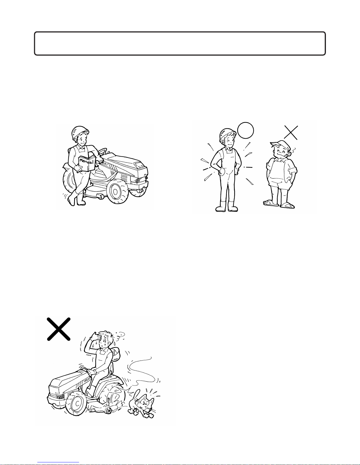
1.1. Before starting the lawn mower for the first
time, read this manual thoroughly and carefully.
Especially abide by the instructions for safe
operation. If you do not, it may result in bodily
injuries.
1.2. Pay attention to the caution labels on the lawn
mower, mower deck and collector, and observe
the instructions they give to avoid physical
injuries.
1.3. Be sure to use necessary protective devices
such as headgear, safety glasses, safety shoes,
ear plugs, gloves, etc.
1.4. If you have consumed intoxicating beverages,
are drowsy from medication, ill, or tired, never
operate the lawn mower.
1.5. When operating, adjusting, or servicing the
lawn mower, always wear substantial shoes and
long trousers. Avoid wearing long loose clothes,
accessories or letting long hair hang loose,
which could be caught in rotating parts or on
projections.
1.6. When you let someone else operate the lawn
mower, instruct this person how to operate the
lawn mower and also advise the reading of this
manual. Never lend the mower to anyone who
cannot understand the contents of this manual
and safety labels. Operation of the lawn mower
by a person unfamiliar with the lawn mower
may lead to an unexpected accidents.
1.7. Never permit the following persons to operate
the lawn mower:
-Persons not properly trained to operate the lawn
mower
-Persons who cannot understand the instructions
mentioned in this operation manual and on the
caution labels
- Pregnant women
- Children
Local regulations may restrict the age of the
operator.
1.8. Inspect the lawn mower periodically. If not, this
may not only shorten the lawn mower's service
life but also make safe and efficient operation
impossible.
I. FOR SAFE OPERATION
SXG
6
2.BEFORE STARTING THE LAWN MOWER
2.1. Set up an operation plan with sufficient time
allowance. A tight plan may result in unexpected accidents. Especially when operating the
lawn mower under extremely hot, cold, or
humid circumstances, set up an operation
schedule or method which will ensure operational safety.
2.2. Thoroughly inspect the area where the lawn
mower is to be used and remove all stones,
sticks, wires, and other foreign objects.
Otherwise, they will be hit by the mower
blades, which may lead to serious accidents.
2.3. The lawn mower is equipped with various safety systems. All safety shields, guards, and covers should always be in position and functioning properly.
2.4. Before starting the engine, make sure that
everything is safe around the lawn mower and
all control levers are in the neutral or off positions, the parking brakes applied, and the PTO
lever in the OFF position. Otherwise, unexpected accidents may occur.
2.5. Start the engine with the starter switch only.
Never attempt to start the engine by shorting
the terminals, or the lawn mower may move
abruptly, and result in unexpected accidents.
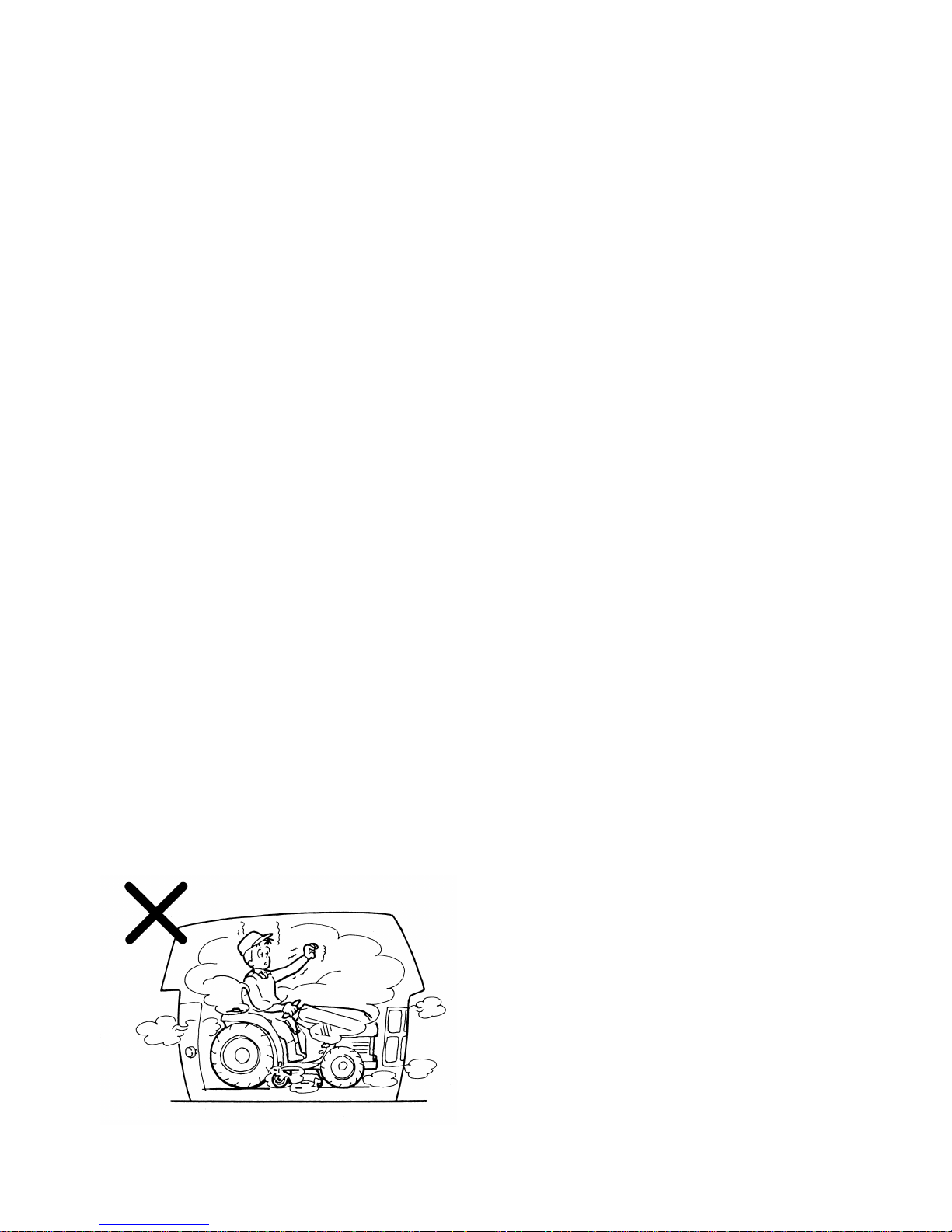
2.6. Never start the engine in a closed place. Exhaust fumes contain poisonous carbon monoxide,
so sufficient ventilation should be provided
when starting the engine indoors.
2.7. Make sure if safety around the lawn mower and
move slowly when starting. Abrupt starting may
cause unexpected accidents.
2.8. Become familiar with the operation, particularly, the stopping of the lawn mower. You should
be skilful enough to be able to stop the lawn
mower at will.
2.9. When your lawn mower is equipped with an
implement other than a standard mower deck,
such as a collector, a cabin, etc., never fail to
ask your dealers about machine balance.
Always follow their advice.
2.10.Keep in mind that the operator or user is responsible for the accidents or hazards caused by
the lawn mower to other people or their property.
2.11.Especially before starting the mower, be sure to
perform advised pre-operation inspections
especially on the brakes and inspect visually to
see that the blade and blade tightening nuts are
not worn, damaged or loose. Replace worn or
damaged blade and nuts as an assembly to preserve blade balance. Otherwise, poor braking or
scattered broken blades may result, which is
very dangerous.
2.12.When operating the lawn mower equipped with
attachment which is not ISEKI-made at the
slope, be sure to equip with lawn mower with
balance weights. Order the following parts to
secure your safty at the slope and install suitable weights with the lawn mower.
•Front hitch
(1620-410-001-1F) ....................1pc
•Front weight(15)
(1614-922-200-1B)....................1pc
If you have any question, please consult your
dealer.
2.13.Machine weight balance is a very important
factor for safe operation. When your machine is
equipped with an implement such as a collector, a cabin, etc., never fail to ask your dealers
about machine balance. Always follow their
advice.

I. FOR SAFE OPERATION
7
3.OPERATION OF THE LAWN MOWER
3.1. During operation, never allow anyone, especially children, and animals to be in the vicinity of
the lawn mower, especially near the discharge
of the mower deck.
3.2. When you are working with co-workers, be
sure to alert them by signalling before you take
a new action.
3.3. Be sure to mow only in daylight. Mowing in the
dark may cause unexpected accidents.
3.4. When operating the lawn mower, you should be
seated in the operator's seat properly, hold the
steering wheel by both hands, and look in the
direction in which the lawn mower advances.
Avoid looking aside or holding the steering
wheel by one hand during operation.
3.5. Always be sure to operate the lawn mower from
the driver's seat. Never attempt to get on or off
the lawn mower while it is travelling.
3.6. Never allow other persons to get on the lawn
mower during operation.
3.7. When turning the lawn mower, slow down sufficiently. Turning at high speed may cause the
lawn mower to turn over.
3.8. Never attempt to depress the dif-lock pedal
while turning around the lawn mower. Turning
with the dif-lock on may cause the lawn mower
to turn over.
3.9. When reversing the lawn mower, make sure of
the safety conditions behind.
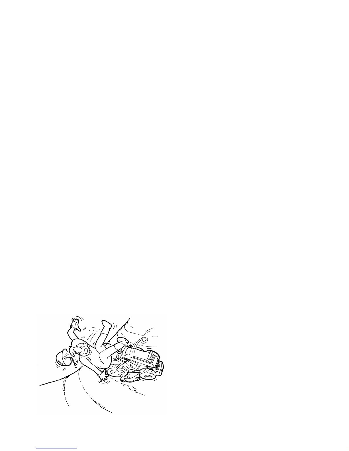
3.10.Never operate the lawn mower in terrain where
there are ditches, holes, or steps easy to collapse. In such a place, the lawn mower could
turn over or fall.
3.11.Befor making access to moving parts, stop the
engine, and keep your hands, feet, clothing,
accessories and etc. away so as not to be caught
in the moving parts of the lawn mower
3.12.Always pay attention in lawn of the lawn
mower to avoid obstacles such as corner stones,
stubs, sprinkler heads, etc. When there is an
obstacle that cannot be removed, provide a marker flag as a warning to keep away from it
when mowing. When approaching the obstacle,
slow down the lawn mower sufficiently to avoid
it.
3.13.Never rest a foot on the brake pedal. If so, the
brakes wear rapidly, which may lead to serious
accidents.
3.14.Adjust the cutting height with the gauge wheels
in accordance with the condition of the ground
surface at the working site. Mowing on rough
ground with low cutting height may cause the
blades to hit soil or stones, which is very dangerous.
3.15.After striking a foreign object, stop the engine
and inspect the lawn mower and the mower
deck for damage and be sure to make repairs
before mowing again.
3.16.Be sure to keep the grass discharging part
clean. A clogged discharging part may cause
the discharge cover to open, resulting in scattering of grass and stones, which is very dangerous.
3.17.Never allow grass or leaves to accumulate
around heated parts such as the engine and the
muffler, or this may cause a fire.
3.18.Before moving the lawn mower to another
place, be sure to stop the mower blades and lift
up the mower deck. Otherwise, they may hit
stones and scatter them around, which is very
dangerous.
3.19.When driving over a levee or a step, stop the
mower blades, lift up the mower deck, and
move the lawn mower straight to the levee and
make it climb over slowly. Avoid climbing over
a levee too high, or the lawn mower may fall
sideways or turn over.
3.20.Before stopping the engine, be sure to lower the
mower deck onto the ground, apply the parking
brakes, and shift the PTO lever to the OFF position.
SXG
8
3.21.Before leaving the lawn mower, stop the
engine, lower the mower deck onto the ground,
draw the engine key, apply the parking brakes,
and chock the wheels. The lawn mower should
be parked in a place which is flat and spacious,
and has hard surface in order to avoid unexpected moving of the lawn mower.
3.22.Never attempt to use the lawn mower to draw
an implement or a trailer. It is not designed to
draw a load.
4. OPERATION ON A SLOPE
We cannot recommend this lawn mower be operated
on a slope, but advise you to use a lawn mower
designed for slope operation. On a slope, various elements of operation such as slope angles, ground conditions, way of operation, grass conditions, etc. may
lead to slipping, or over-turning of the lawn mower,
which may result in bodily injury.
If the lawn mower has to be used on a slope, remember there is on such thing as a "safe" slope. Never
use it on a slope of more than "12˚", and be sure to
abide by the following instructions. Even if using it
on a slope of less than "12˚", be sure to abide by the
following instructions.
•A slope angle of 12˚is specified with the lawn
mowers equipped with the attachments mentioned respectively.
When your lawn mower is equipped with an
implement other than standard, such as a collector, a cabin, etc., never fail to ask your dealers about machine balance. Always follow their
advice.
- The lawn mower is not equipped with any
attachments or a cabin.
- The lawn mower is equipped with a standard
mower deck.
4.1. Be sure to wear a helmet during operation.
4.2. Operate at sufficiently low speeds.
4.3. When turning, be sure to slow down sufficiently.
4.4. Avoid sudden starting and stopping.
4.5. Operate the lawn mower up and down across
the contour lines of the hill. Never operate
along the contour lines.
4.6. Never perform mowing operation on wet grass.
4.7. Never park the lawn mower on a slope.
4.8. Pay attention to other possible causes of danger
which could lead to overturning, etc.
5. DRIVING ON PUBLIC ROADS:
5.1. This lawn mower cannot be driven on a public
road without authorization by a local goverment agency. etc. Therefore it may be illegal for
the lawn mower not only to travel on but also to
cross a public road.
5.2. When transporting the lawn mower on a public
road, load it on a truck.
6. LOADING ONTO OR UNLOADING FROM A
TRUCK:
6.1. When loading the lawn mower onto a truck,
turn off the truck's engine, apply the parking
brakes to the truck, and chock the wheels to
avoid unexpected moving of the truck.
6.2. Pay sufficient attention to safety conditions
around the lawn mower and have it guided by
someone to assist the operator. Never allow
other persons to approach the lawn mower,
especially in lawn of or behind it.
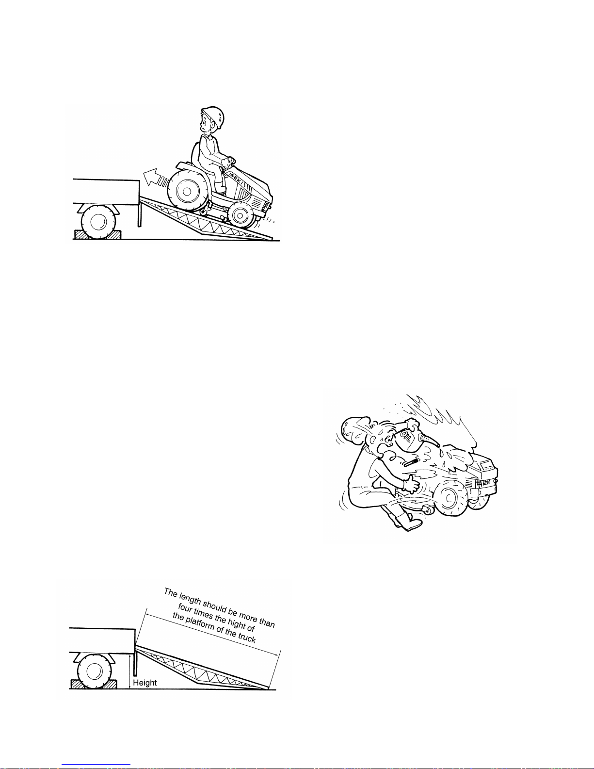
6.3. When loading the lawn mower onto a truck, lift
I. FOR SAFE OPERATION
9
up the mower deck fully and reverse it straight
back at sufficiently low speeds. Drive it forward when unloading it from the truck.
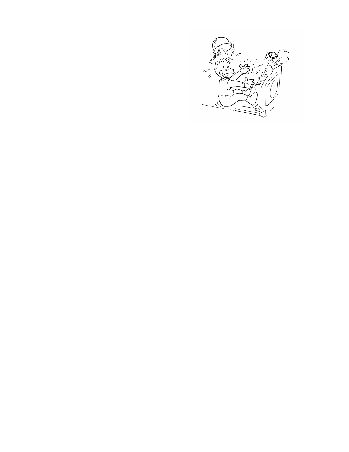
6.4. If the engine stalls unexpectedly on the ramps,
depress the brake pedals immediately and roll
the lawn mower to the ground by releasing the
brakes gradually. Then start the engine and try
again.
6.5. Use ramps with the same or better specifications mentioned below. When the lawn mower
is equipped with the attachments other than
those included in the specifications mentioned
below, ask your dealers for advice.
Specifications of the ramps
for the SXG 19 and SXG 22
• Length.........more than 4 times the height of the platform
.......................................................................of the truck
• Width(effective width)............................more than 30 cm
• Required quantity................................................2 ramps
• Capacity (one ramp).............................more than 750 kg
• Ramps should have anti-skid surfaces.
• The above specifications are effective with the lawn
mower with the following conflgurations.
• mowers are not equipped with any attachments or a
cabin.
• Lawn mowers are equipped with a standard mower
deck.
6.6. Park the truck on hard level ground. Hook the
ramps securely on the platform of the truck
with the top of the ramp level with the platform.
6.7. Drive the lawn mower carefully at the moment
the lawn mower moves from the ramps onto the
platform, for it changes angles abruptly.
6.8. When the lawn mower is loaded on the truck,
stop the engine, apply parking brakes, and
withdraw the starter key, chock the wheels, and
rope it securely to the truck. Refrain from
unnecessary abrupt starting, stopping, and turning during transportation, or the lawn mower
may shift position on the truck, which is very
dangerous.
7. WHEN FILLING WITH FUEL:
7.1. Never smoke while refilling with fuel, nor
allow any open flames near the lawn mower.
7.2. Never open the fuel tank cap while the engine
is running or while it is still hot after operation.
Wait until the engine cools down sufficiently.
7.3. Provide adequate measures to prevent fuel from
spilling when pouring it into the fuel tank. Spilt
fuel should be wiped off completely.
7.4. Avoid refueling indoors. If this is inevitable,
provide sufficient ventilation.
7.5. Replace the fuel tank and container caps
securely.
7.6. Store fuel in containers specifically designed
for this purposes.
SXG
10
8. MOUNTING AND DISMOUNTING OF THE
MOWER DRIVE SHAFT
The mower gear box is driven through a drive shaft
with universal joints from the lawn mower. When
connecting or disconnecting the shaft, follow the
next instructions.
8.1. Lower the mower deck onto the gournd, stop
the engine, draw the engine key, and apply the
parking brakes before mounting or dismounting
the drive shaft.
8.2. Shift the PTO lever to the OFF position(N).
8.3. Make sure that the PTO shaft and mower blades
stop completely.
8.4. The drive shaft should be mounted or dis
mounted at the lawn mower side. Never leave
the shaft connected only at the lawn mower
side. If the PTO shaft be driven unexpectedly,
the shaft will be swung around and damage the
lawn mower or cause serious accidents.
9. LAWN MOWER MAINTENANCE:
9.1. Never start the engine in a closed place.
Exhaust fumes contain poisonous carbon
monoxide, so sufficient ventilation should be
provided when starting the engine indoors.
9.2. Be sure to wear safety glasses and gloves when
servicing the lawn mower.
9.3. When servicing the lawn mower or mounting or
dismounting the mower deck, place the lawn
mower on level, hard ground.
9.4. Service the lawn mower in a place sufficiently
illuminated, or darkness may cause unexpected
accidents.
9.5. When servicing the lawn mower or mounting or
dismounting the mower deck, stop the engine
and remove the engine key and apply the parking brakes.
9.6. The engine, muffler, radiator, etc. are very hot
just after operation, so wait until those heated
parts cool down sufficiently to avoid burns.
9.7. Never remove the radiator cap while the engine
is hot or running. Wait until the engine cools
down and then relieve the radiator pressure by
releasing the radiator cap. Carelessly pouring
cooling water into the heated radiator can cause
serious damage to the radiator and the engine.
Careless removal of the radiator cap can cause
serious injury because of superheated water
vapor.
9.8. Before servicing the lawn mower, be sure to
shift the PTO lever to the OFF position and
make sure that the mower blades have stopped
completely. Rotating blades may cause serious
accidents.
9.9. When servicing the lawn mower, use proper
tools. Using makeshift tools may lead to
injuries or poor service, which may result in
unexpected accidents during operation.
9.10.When removing a tyre, chock other tyres and
support the lawn mower securely. When
installing tyres, be sure to tighten the wheel
nuts to the specified torque. Loose nuts may
cause serious accidents.
9.11.When servicing the mower blades, pay sufficient care so your hands or fingers are not cut
by them. As the three blades are driven by one
belt, turning one blade will cause the other
blades to turn.
9.12.Never step on the mower deck, or the mower
deck may be damaged or deformed, which may
lead to breakdown or accidents.
9.13. A first aid kit and a fire extinguisher should be
I. FOR SAFE OPERATION
11
kept in a place always in instant access.
9.14.Avoid high-pressure fluids. Escaping fluid
under pressure can penetrate the skin and cause
serious injury, so keep hands and body away
from pin holes and nozzles ejecting such fluids.
Be sure to consult your dealer about the
hydraulic and fuel injection system troubles.
9.15.If any hydraulic fluid is injected accidentally
into the skin, it must be removed within a few
hours by a doctor familiar with this type of
injury.
9.16.Never allow grass or leaves to accumulate
around heated parts such as the engine and the
muffler, or this may cause a fire.
9.17.Be sure to reinstall the removed parts in place.
Never attempt to start the engine with any parts
removed.
9.18.Never attempt unauthorized modification of the
lawn mower as this could be very hazardous.
Damaged or worn parts should be replaced with
ISEKI genuine spare parts. Unauthorized parts
may cause breakdown of the lawn mower, acci
dents, and ISEKI warranty to expire.
9.19.Keep all nuts, bolts and screws tight to be sure
that the equipment is in safe working condition.
10. ELECTRICAL SYSTEM
10.1.Before servicing the electrical system, be sure
to stop the engine, lower the mower deck on the
ground, draw the starter key, shift the PTO lever
to the OFF position, and apply parking brakes.
10.2.Before inspecting the connections of the electrical system, be sure to disconnect the negative
terminal of the battery to avoid short circuits
and electric shocks.
10.3.Loose connections, terminals, and damaged
wiring should be repaired as soon as possible.
They will not only deteriorate the performance
of electric parts but also may cause short circuits, leading to fires.
10.4.The surroundings of the wiring and the battery
should be kept clean, or accumulated grass or
chaff may catch fire.
10.5.Never smoke nor allow any open flames nearby
or sparks, which may be caused by short circuits during servicing the battery. The battery
generates explosive gases(hydrogen and oxygen) during charging, so the battery should
becharged in a place well ventilated to let such
explosive gases diffuse smoothly. Otherwise
settled gases may catch fire.
10.6.Battery electrolyte is diluted sulphuric acid, so
it is corrosive and naturally poisonous. Never
allow acid to contact skin or clothing, or it may
cause burns. Always wear a face shield to avoid
acid getting in eyes. If acid contacts skin or
clothing, wash off immediately with clean
Parts code of blade
Punched ID
SCMA 54
Left 8665-306-001-00
I 8665 A
Right 8665-306-002-00
I 8665 B
SCMA 48
Left 8663-306-001-00
I 8663 A
Right 8663-306-002-00
I 8663 B
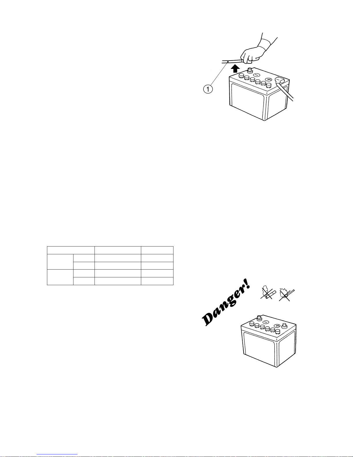
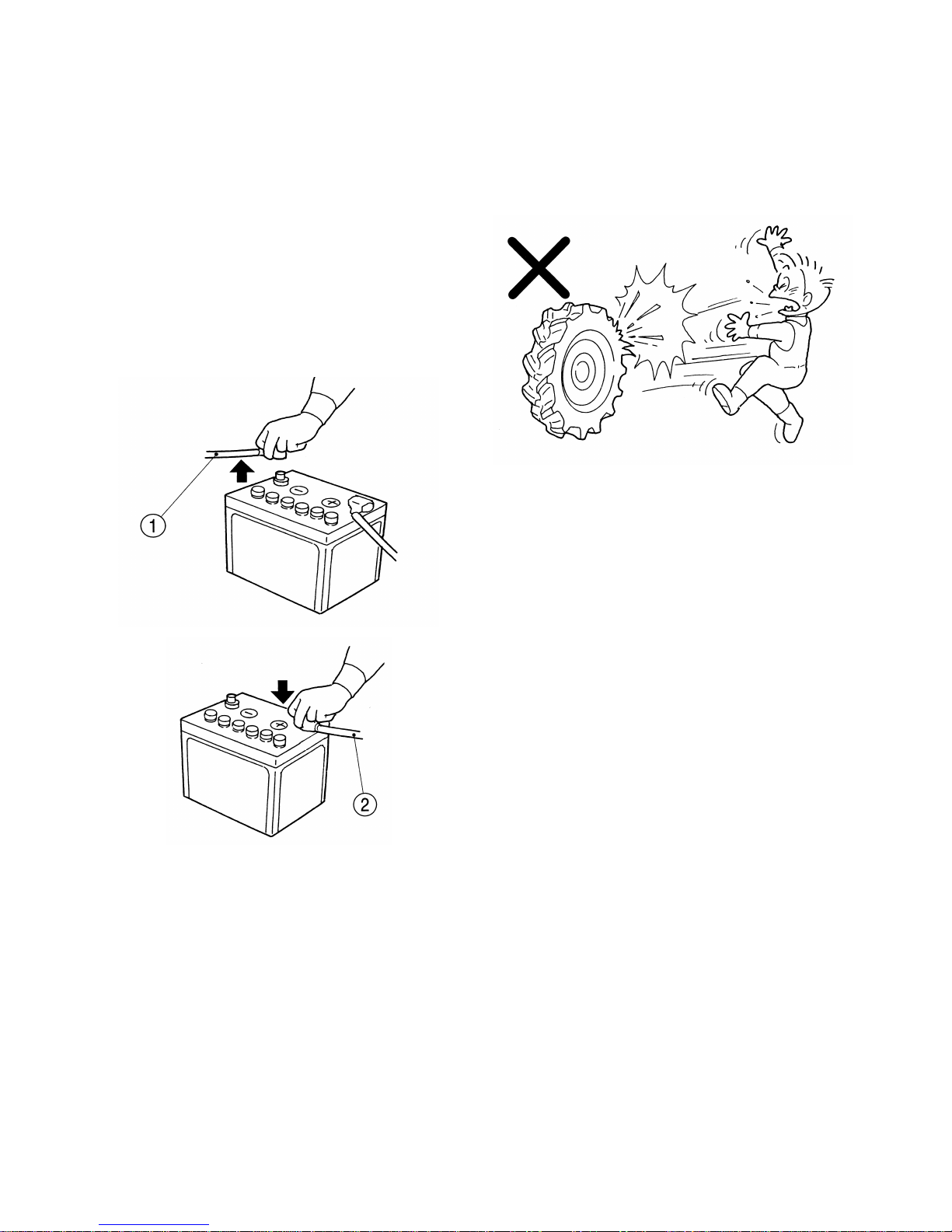
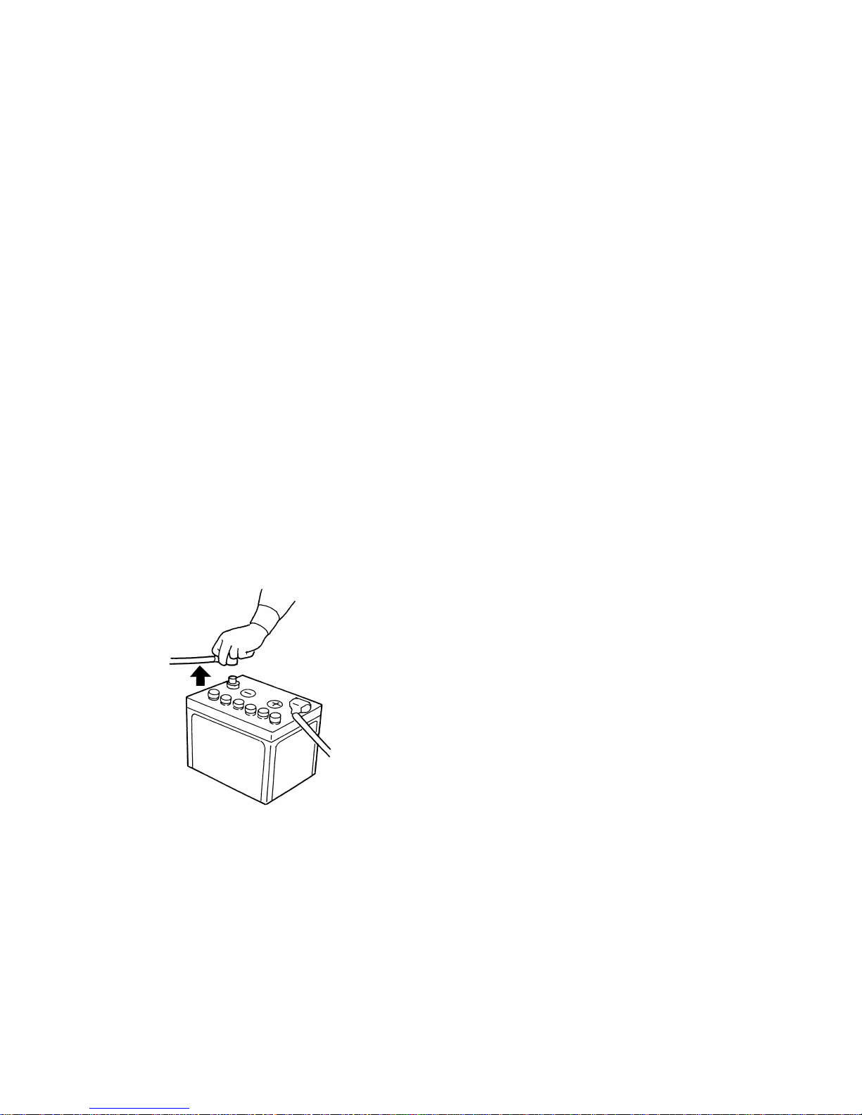
(1) Negative cord
SXG
12
water. If acid contacts eyes, flush immediately
with clean water and get medical attention.
10.7.Before servicing and mounting or dismounting
the battery, stop the engine, draw the starter
key, and apply the parking brakes. Otherwise,
electric parts may be damaged.
10.8. When disconnecting the battery, disconnect the
negative(-) cable first, while connect the positive(+) cable first when connecting the battery.
Wrong order of disconnecting or connecting
the battery will cause sparks, which is very
dangerous.
10.9.When using booster cables, observe the following instructions to avoid accidents:
•Remove the filler caps of battery cells ahead of
time to lessen explosive power of gases if they
should catch fire.
•Before connecting booster cables, be sure to
stop the engine.
•Use booster cables of sufficient capacity, or
they may be heated or burnt out.
11. TYRES AND WHEELS
11.1.Be sure to keep tyre pressures at the levels
specified in this manual. Excessively high tyre
pressure may result in explosion, which may
lead to physical accidents.
11.2.If a cut is found in a tyre and the cut reaches
the cords, do not use it. Such a tyre may
explode.
11.3.Before replacing or repairing tyres, tubes, or
rims, consult your dealers ahead of time. Such
operation should be performed by trained
mechanics.
12. BEFORE STORING THE LAWN MOWER
12.1.After opeation, be sure to close the fuel cock to
prevent fuel from spilling, as spilled fuel may
catch fire.
12.2.Never allow grass or leaves to acoumulate
around heated parts such as the engine and the
muffler, or this may cause a fire.
12.3.Be sure to remove the ignition key to prevent
unexpected accidents caused by engine starting
by untrained persons or children.
12.4.When storing the lawn mower with the mower
deck attached, be sure to lower the mower deck
on the ground. Otherwise manipulation of the
lift lever by untrained person or children may
cause unexpected accidents.
12.5.Store the lawn mower in a place provided with
sufficient illumination. Inspection and moving
of the lawn mower in a dark place may lead to
(1) Negative cord (2) Positive cord
I. FOR SAFE OPERATION
13
unexpected accidents.
12.6.When the lawn mower is to be stored in a
closed place like a garage or a barn, provide
sufficient ventilation for exhaust gases. Exhaust
fumes can be lethal.
12.7.To avoid fire hazard, keep the engine, muffler,
battery, and fuel storage area free of grass,
leaves, or excessive grease.
12.8.Never cover a hot lawn mower just after operation with a tarpaulin or the like, or the heated
engine and related parts may cause a fire.
13. LONG TERM STORAGE
13.1.Before storing the lawn mower for long period
of time, disconnect the battery cables to prevent
them, in case they are gnawn by rats, from
causing a short circuit, which may lead to a
fire. When disconnecting the battery, disconnect the negative(-) cable first, while connecting the positive(+) cable first when connecting
the battery. Wrong order of disconnecting on
connecting the battery will cause sparks, which
is very dangerous.
SXG
14
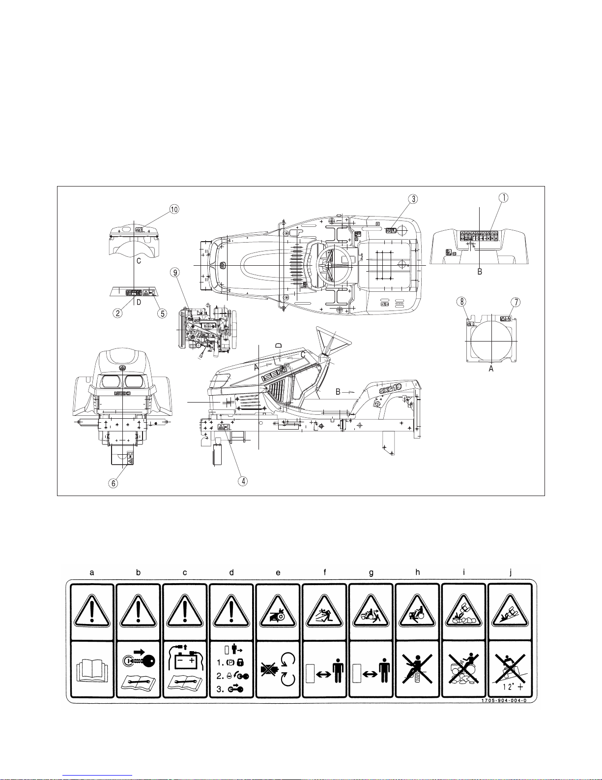
14. CAUTION LABELS & THEIR POSITIONS
•Caution labels on the lawn mower and the mower deck and the lawn collector
The following labels are stuck on the lawn mower and mower deck. You should of course read the caution instructions in the manual. But never fail to read the labels on the lawn mower and mower deck as
well. Their respective code numbers are also mentioned below, so order them from your dealer if any of
them are lost or damaged.
On the lawn mower
(1) Caution label
(Code No.1705-904-004-0)
I. FOR SAFE OPERATION
15
a. Read the manual thoroughly.
b. Shut off the engine and remove the starter
key before servicing or repairing the
machine.
c. The negative terminal of the battery should
be disconnected before servicing or repairing the machine.
d. When leaving the machine,
Apply the parking brakes,
Shut off the engine, and
Remove the engine key.
e. Risk of injury
Keep all safety devices such as guards,
safety switches, etc in place and working
properly.
f. Risk of injury
Remove objects from around the machine
that could be thrown by blades and keep
people away from the machine before starting the machine.
g. Risk of running over a person
Watch behind before reversing the machine
and keep people from around the machine
before starting the machine.
h. Risk of running over a person
Don't allow any other person to ride on a
wheel fender or any place other than the dri
ver's seat of the machine.
i. Risk of overturning or crushing
Do not operate the machine in any place
where it could slip or tip over.
j. Rist of overtuning or crushing
Avoid operating the machine on a slope of
over 12˚.
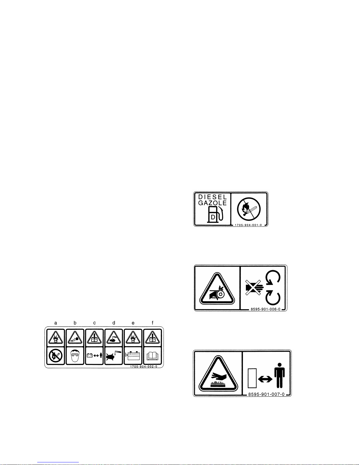
(2) Battery label
(Code No. 1705-904-002-0)
a. Avoid sparks and flames.
b. Wear a eye protection gear.
c. Keep battery out of reach of children.
d. Beware of sulphuric acid.
e. Beware of explosion.
f. Read the manual thoroughly.
Handle the battery carefully:
- Improper handling of the battery may lead to
explosion. Never short the poles. Keep away
from sparks or flames. When charging or
using, provide sufficient ventilation. Watch
out when using booster cables.
- Battery electrolyte(sulphuric acid) may cause
blindness or burns. Avoid allowing electrolyte
to contact eyes, skin or clothing. In the event
of an accident flush area immediately with
plenty of water. If acid gets into the eyes,
rinse with plenty of water any get medical
attention.
- Never use the battery with the electrolyte
level below the "LOWER" limit, or it may
explode.
- Never replenish exceeding the "UPPER"
limit or the electrolyte may spill out.
(3) Fuel label
(Code No. 1705-904-001-0)
Use diesel fuel only. No open flame.
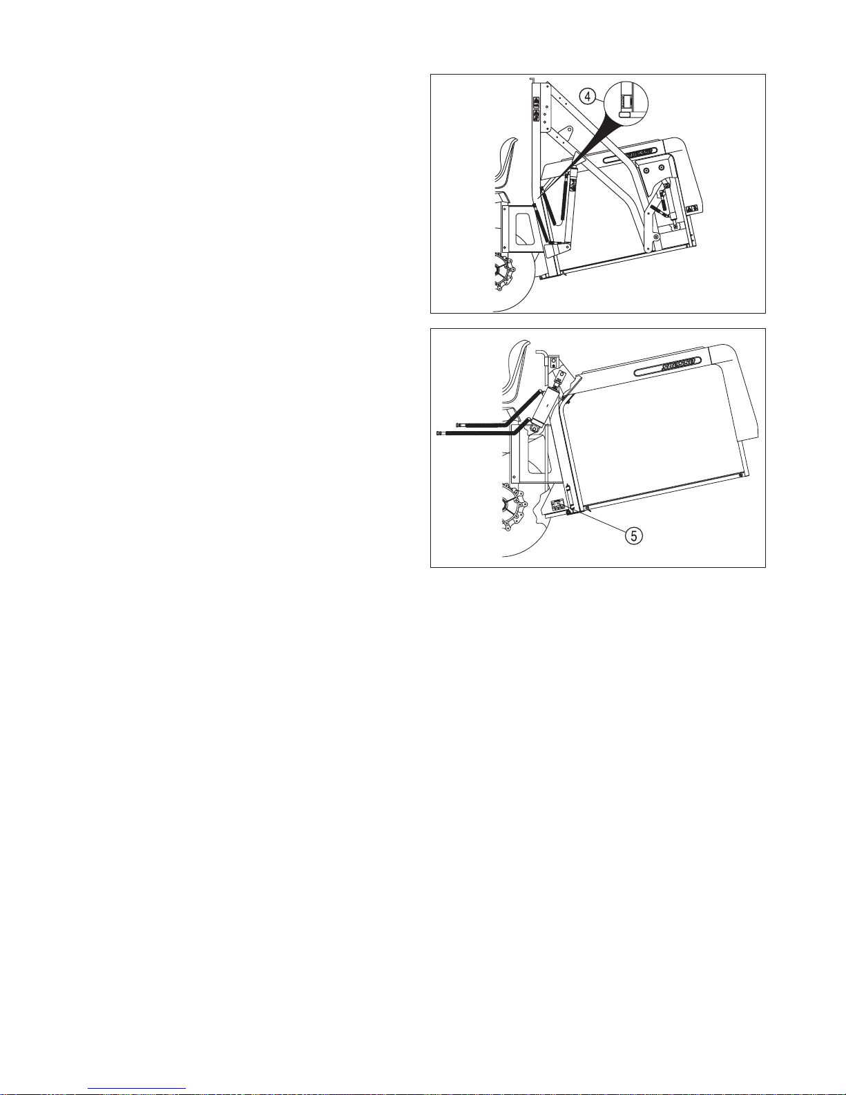
(4) Belt caution label
(5) (Code No. 8595-901-006-0)
(6)
Stay clear of the belt while it is running.
(7) Hot-part caution label
(Code No. 8595-901-007-0)
Stay clear of the heated parts while they are
hot.
SXG
16
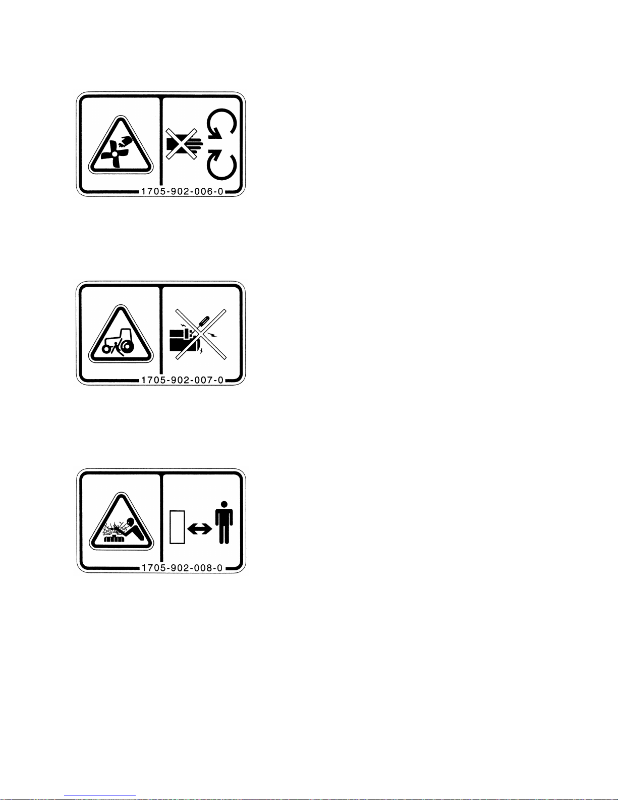
(8) Fan caution label
(Code No.1705-902-006-0)
Stay clear of the fan while it is running.
(9) Starter caution label
(Code No. 1705-902-007-0)
Start engine only with key from seat.
(10) Radiator caution label
(Code No. 1705-902-008-0)
Hot pressurized system. Do not open cap
while radiator is hot.
I. FOR SAFE OPERATION
17
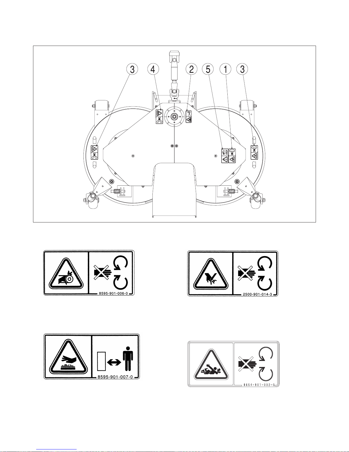
On the mower deck
(1) Belt caution label
(Code No. 8595-901-006-0)
Stay clear of the belt while it is moving.
(2) Hot-part caution label
(Code No. 8595-901-007-0)
Stay clear of the heated parts while they are
hot.
(3) Danger label
(Code No. 2500-901-014-3D)
Stay clear of the mower blades while the
engine i running.
(4) PTO label
(Code No. 8654-901-002-0)
Stay clear of the PTO shaft while the engine
running.

SXG
18
(5) Maintenance label
(Code No. 1593-901-015-0)
Shut off the engine and remove the starter
key before performing maintenance or repair
work.
• Maintenance of the caution labels
- The labels should always be clearly seen,
that is, nothing should obscure them.
- When they have become dirty, wash them
with soapy water and wipe off with soft cloth.
- If any of them are torn or lost, order new
labels from your dealer.
-Anew label should be placed in the same
place where the old one was located.
- When sticking on a new label, clean the
place to enable the label to stick and
squeeze out all air bubbles trapped under it.
- When replacing a part with a caution label
stuck on, a new caution label should also be
ordered.
I. FOR SAFE OPERATION
19
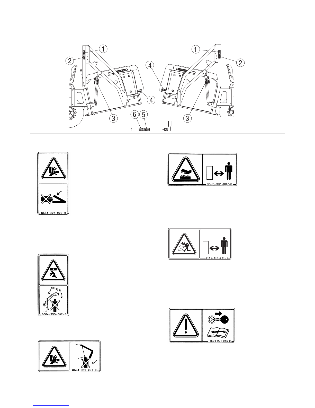
On the collector
High dump collector
(1) Link caution label
(Code No. 8664-905-003-0)
Stay clear of the collector frame while the
container dumping.
(2) Collector caution label
(Code No. 8664-955-002-0)
(3) Door caution lablel
(Code No. 8664-955-001-0)
Stay clear of the container rear frame while
the close of the rear door.
(4) Hot-part caution label
(Code No. 8595-901-007-0)
Stay clear of the heated parts while they are
hot.
(5) Discharge label
(Code No. 8595-901-005-0)
Stay away of the discharge opening of the
mower deck because stones or other hard
objects ejected from the mower may hit you.
(6) Maintenance label
(Code No. 1593-901-015-0)
Shut off the engine and remove the starter
key before performing maintenance or repair
work.
SXG
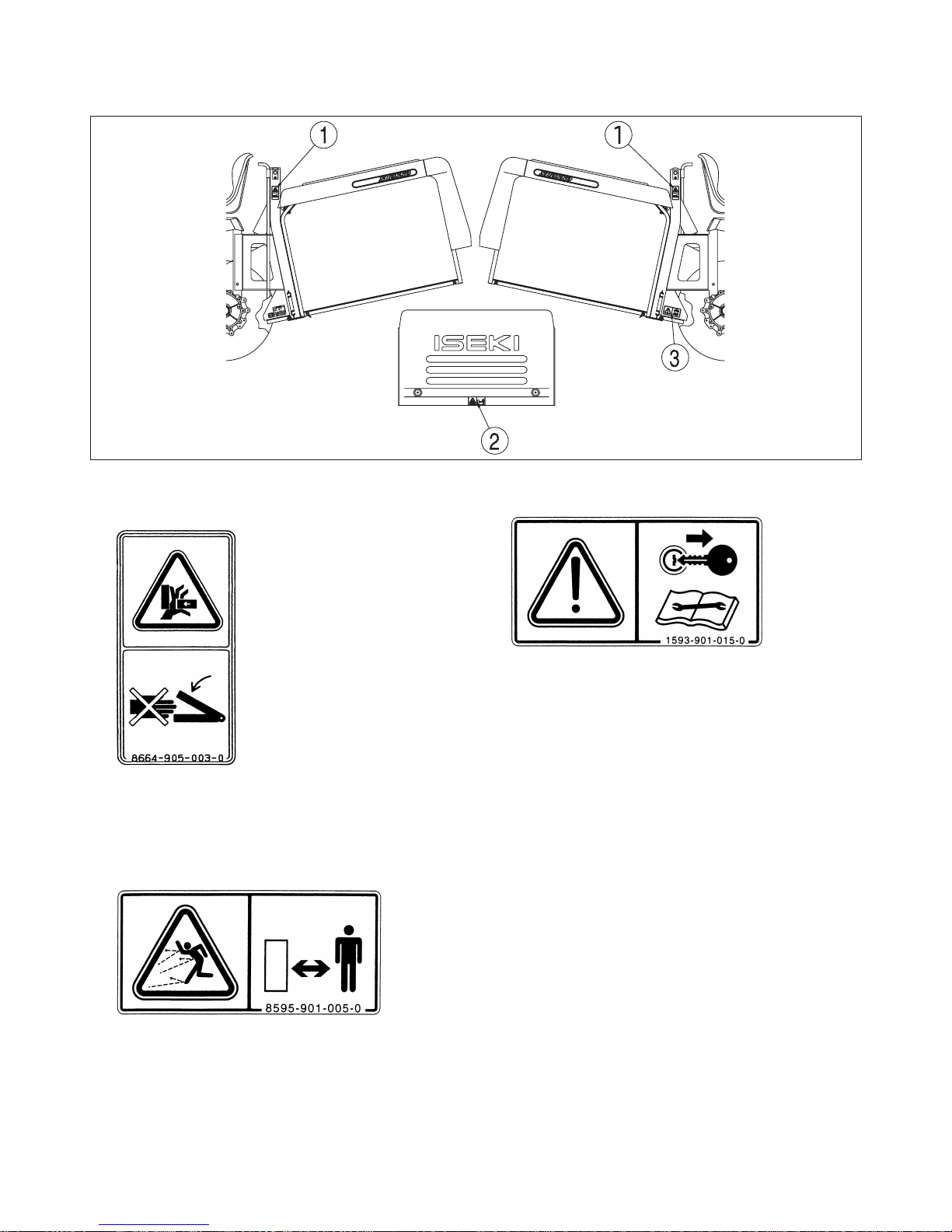
20
Low dump collector
(1) Link Caution label
(Code No. 8664-905-003-0)
Stay clear of the collector frame while the
container dumping.
(2) Discharge label
(Code No. 8595-901-005-0)
Stay away of the discharge opening of the
mower desk because stones or other hard
objects ejected from the mower may hit you.
(3) Maintenance label
(Code No. 1593-901-015-0)
Shut off the engine and remove the starter
key before performing maintenance or repair
work.
II. WARRANTY AND AFTER-SALE CARE
21
WARRANTY
On the warranty of this lawn mower and mower deck, refer to the warranty policy attached.
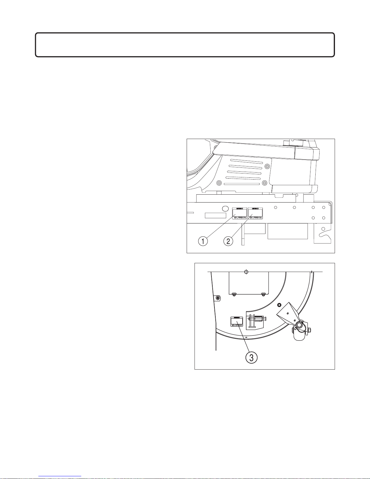
AFTER-SALE CARE
As for breakdown or questions about the lawn mower and mower deck, consult with your dealers identifying
the model and serial number of your lawn mower.
Lawn mower
(1) Model name and serial number
(2) Engine model name and serial number
Mower deck
(3) Model name and serial number
II. WARRANTY AND AFTER-SALE CARE
SXG
22
Collector high dump (SBC550X-H)
(4) Model name and serial number
Collector low dump (SBC550X-L)
(5) Model name and serial number
SUPPLY LIMT OF SPARE PARTS
•The supply time limit of the spare parts for this model is 12 years after manufacture of the model is stopped. Even within the supply limit, the delivery date of some parts have to be determined after negotiation.
•The supply of spare parts terminates when the limit mentioned above is exceeded. But orders for parts
after the limit may be met after negotiation about the delivery date, price etc.

MOWER DECKS
III. SPECIFICATIONS
23
LAWN MOWERS
III. SPECIFICATIONS
Model
SXG 22 H SXG 19 H
UE UGE UE UGE
Dimensions
overall length 2110 (83.1 in.)
overall width 1130 (44.5 in.) 1100 (43.3 in.)
overall height 1265 (49.8 in.)
Weight
515 kg (1135 lb.) 520 kg (1145 lb.) 510 kg (1124 lb.) 515 kg (1135 lb.)
Engine
Model E3112-G03 E3100-G01
Type Vertical, Water-cooled, 4-cycle, diesel
Combustion chamber
Swirl chamber type
No, of cylinders 3
Total displacement
1123 1006
Output (net)
15.5 kw (21ps)
2600 min
-1
(rpm)
14 kw (19 ps)
2600 min
-1
(rpm)
Fuel Diesel fuel
Fuel tank capacity 18.5 liters (40 IMP. gal.)
Transmission
Main transmission
HST (Hydrostatic transmission)
Rear axle Chain drive
Travel
Speeds
Forward 0-16.5 km/h (0-10.3 mph) 0-15km/h (0-9.4 mph)
Reverse 0-10 km/h (0-6.3 mph)
Wheel base 1450 mm 1365 mm
Wheel Tread
Front 910 mm
Rear 865 mm 860 mm
Driving system 2WD
Steering system Power steering
Brake system Dry internal-shoe expanding
No. of Brake
1 (Before dif.)
2 (After dif.)
1 (Before dif.)
2 (After dif.)
Tyre size
Front 210 x 60 D-8 16 x 6.5-8
Rear 250 x 60D-14 23 x 10.50-12
PTO Front 1750 min-1(rpm)
PTO Clutch Belt tension clutch
Minimum ground
clearance
Lawn mower 140 mm (5.5 in.) 110 mm (4.3 in.)
Mower lift 150 mm (5.9 in.)
Model SCMA 48 & 54 SCMA 48
Dimensions
Overall length 945 mm (37.2 in.) 905 mm (35.6 in.)
Overall width 1440 mm (56.7 in.) 1285 mm (50.6 in.)
Overall height 385 mm (15.2 in.)
Type Rotary mower
Cutting width
1220 mm (48 in.) & 1372 mm (54 in.)
1220 mm (48in.)
No. of blades 2
Cutting-height adjustment1 Adjustable in 7 stages by pin replacement
Cutting-height adjustment2 Dial
Cutting heights 30 - 120 mm (1.2 - 4.7 in.)
Weight
Deck 106 kg (233lbs) 96 kg (211 lbs)
Link 9 kg (20 lbs)

SXG
24
Collectors
Model
SBC 550 X
H (high dump) L(low dump)
Type Blower less center collect high & low dump collector
Dimensions
overall length 1400 mm (55.1 in.) 1410 (55.5 in.)
overall width 1115 mm (43.9 in.) 920 (36.2 in.)
overall height 1440 mm (56.7 in.) 1000 (39.4 in.)
Weight 138 kg (304 lbs.) 70 kg (154 lbs.)
Container capacity 550 liters
Height of lift 1900 mm (74.8 in.) Height of dump - 890 mm (35 in.)
Lift system Hydro Dump system Hydro Hydro
No. of lift cylinder 2 No. of dump cylinder 2 1
Piston & cylinder
Dia. x stroke
Lift 25 x 40 x 450 mm -
Dump 20 x 30 x 150 mm 30 x 65 x 115 mm
Full censor system limit switch
IV. NAMES OF MAJOR COMPONENTS
25
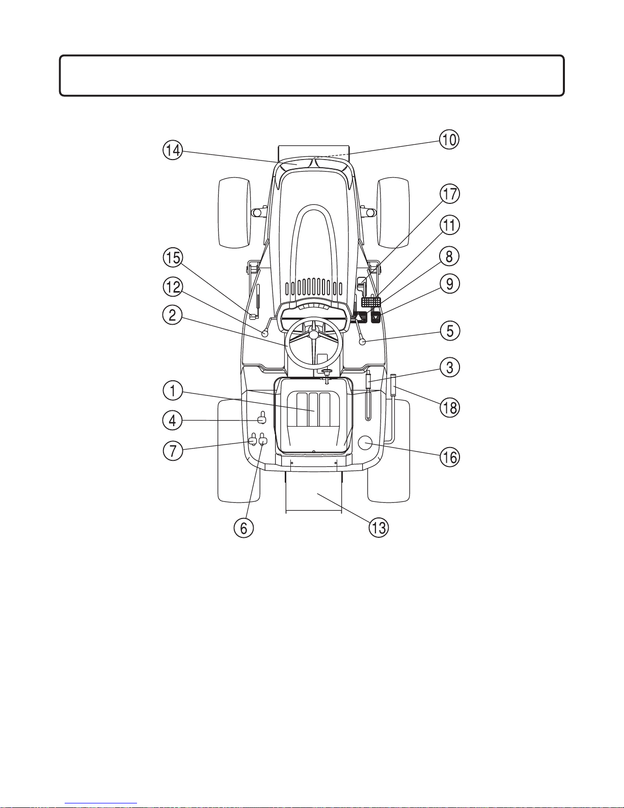
(1) Seat
(2) Steering wheel
(3) Parking brake lever (UGE)
(4) Lift lever
(5) PTO lever
(6) Collector lift lever
(7) Collector dump lever
(8) HST forward travel pedal
(Forward control)
(9) HST reverse travel pedal
(Reverse control)
(10) Front PTO shaft (OPT)
(11) Master brake pedal
(12) Throttle lever
(13) Shooter
(14) Headlight
(15) Dif lock pedal
(16) Fuel tank cap
(17) Parking brake lever (UE)
(18) Cleaning lever
IV. NAMES OF MAJOR COMPONENTS

SXG
26
1. CONTROL PANEL
(UE TYPE)
V. CONTROLS AND METERS
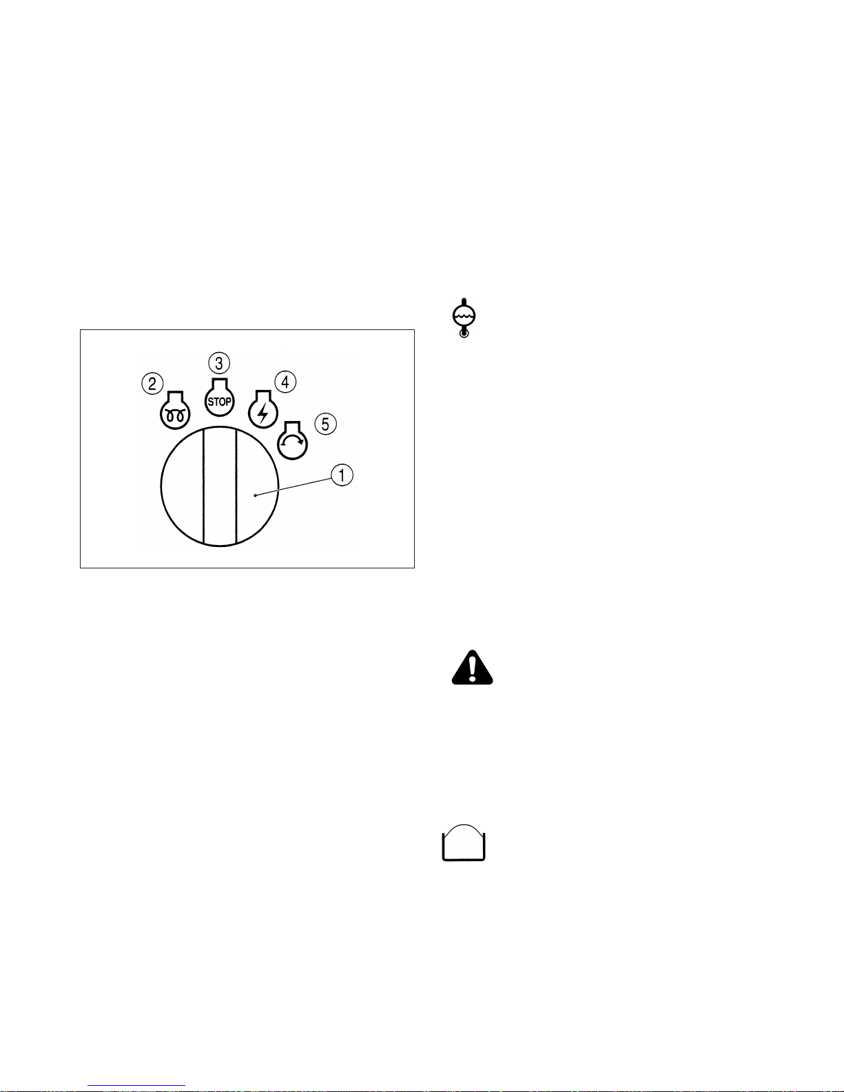
(1) Starter switch
(2) Throttle lever
(3) Monitor lamp array
(4) PTO lever
(5) Hourmeter
(6) Headlight switch
(UGE TYPE)
(1) Starter switch
(2) Throttle lever
(3) Monitor lamp array
(4) PTO lever
(5) Hourmeter
(6) switch position
(7) Turning signal lamp
(8) Combination switch
(9) Hazard switch
(10)Parking lamp
(11) High beam lamp
V. CONTROLS AND METERS
27
1.1. STARTER SWITCH
G: Glow position: the engine is pre-heated in
this position.
$: OFF position: the engine stops and all
electric circuits are turned off.
O: ON position: the key turns to this position
after starting the engine and remains there
during operation.
s:START position: the starter motor is
switched on in this position.
1.2. THROTTLE LEVER
With this lever, the engine speed is controlled.
t:Turn this lever towards the "tortoise"
mark, the engine decelerates.
r:Turn this lever towards the "hare" mark,
the engine accelerates.
1.3. MONITOR LAMP ARRAY
• Charge lamp:
b: The lamp lights up while the battery is
not being charged. It also lights up when
the key turns to the ON (O) position or
the START. (s) position while the
engine stops, but turns off as soon as the
(1) Starter switch
(2) Glow position
(3) OFF position
(4) ON position
(5) START position
engine starts.
• Oil pressure lamp:
o: The lamp lights up when the engine oil
pressure is not circulating normally. It
also lights up when the key turns to the
ON (O) position or the START (s) position while the engine stops, but turns off
as soon as the engine starts.
• Engine coolant warning lamp:
: The lamp lights up when the engine
coolant is over-heated.
Important:
When the engine coolant is over-heated, the monitor lamp is lit and at the same time the buzzer
sounds while the PTO lever is in the "ON" (M)
position. The buzzer turns off when the PTO lever
is shifted to the "OFF" (N) position.
When the monitor lamp is lit, shift the PTO lever
to the "OFF" (N) position, decelerated the
engine to idling, and wait until the lamp turns off.
When the lamp turns off, stop the engine and correct the trouble (clogged grass or dust around
engine, radiator, etc.). Then re-start operation.
Warning:
When inspecting the radiator, be sure that the
engine cools down sufficiently. Never release the
radiator cap while the coolant is hot, or boiling
water will gush out.
• Grass collector lamp:
: The lamp works only when the machine
is equipped with the grass collector It
lights up when the collector is filled with
grass. The buzzer sounds also when the
PTO lever is in the "ON" position. It
turns off when the lever is shifted to the
"OFF" position. When the collector is
emptied, the lamp turns off.
SXG
28
• Turning signal lamp (UGE TYPE)
: The lamp blinks while turning signal
switch is ON.
1.4. PTO LEVER
With this lever the PTO can be either engaged to
spin or disenaged to stop.
M: Shift the lever to the position indicated
by this mark, and the front PTO shaft
starts spinning.
N: Shift the lever to the position indicated
by this mark, and the front PTO shaft
stops spinning.
Important:
When engaging the PTO clutch, slow down the
engine speed sufficiently for safety.
1.5. HOURMETER
The hourmeter counts operation hours of the
lawn mower and shows them.
The lowest figure indicates one tenth hour of
operation.
1.6. Headlight switch (UE TYPE)
: The light in front grill light up while the
headlight switch is ON.
1.7. Position switch (UGE TYPE)
: The light in combination lamp (option)
light up while the position switch is ON.
1.8. Combination switch (UGE TYPE)
This is a combination switch, which incorporates
the headlight switch, turning signal switch and
horn button.
• Headlight
• Turning signal
• Horn
1.9. Hazard switch (UGE TYPE)
: The lamp and turning signal lamps
blinks while hazard switch is ON.
1.10. Parking lamp (UGE TYPE)
: The lamp light up with key switch ON
while parking lever is pulled upward to
lock brakes.
Important:
Always disengage brake lever and confirn that the
lamp is OFF before driving the lawn mower to
prevent abnormal brake wear.
1.11. High beam signal lamp (UGE TYPE)
: The lamp light up while high beam light
of combination switches is ON.
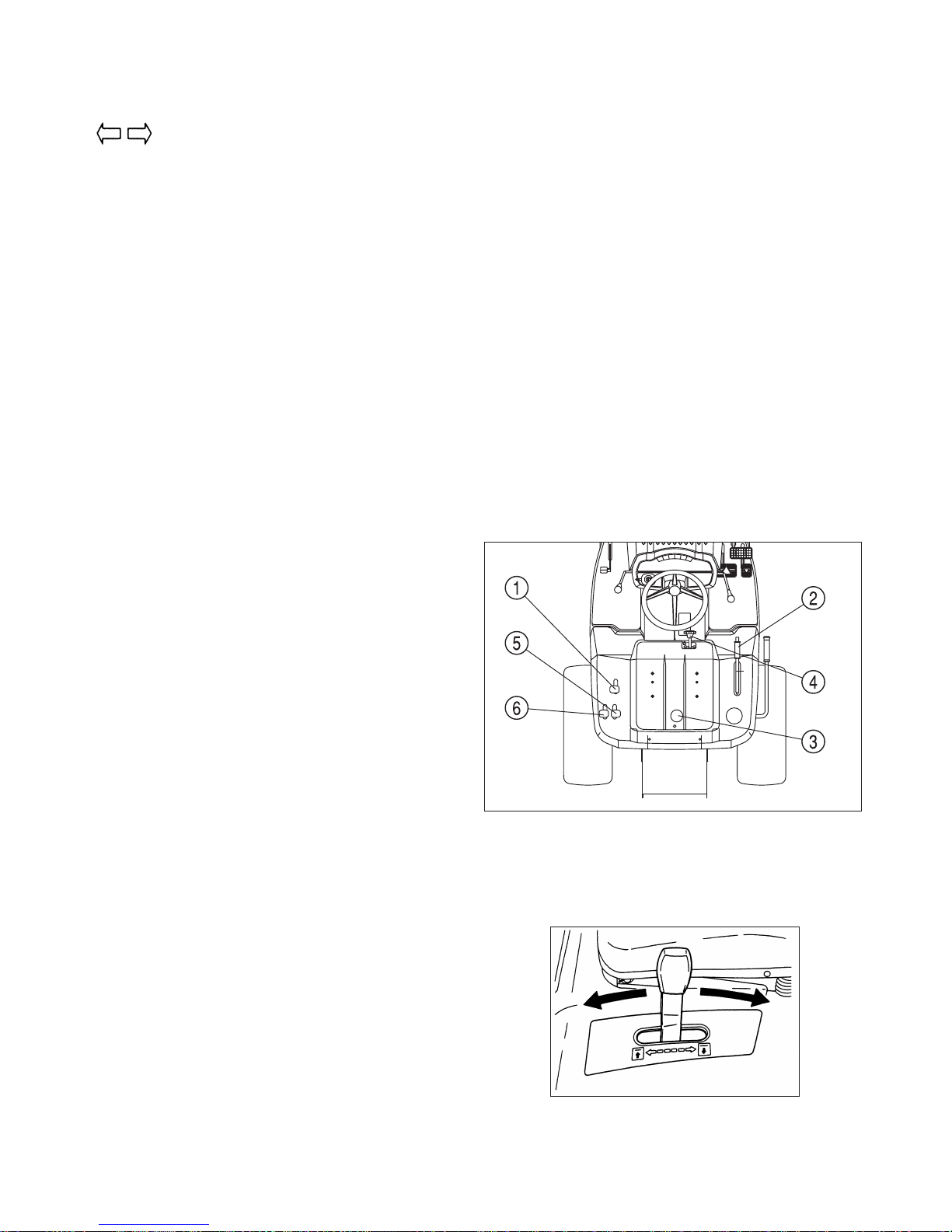
2. FENDER (WING) PANEL
(1) Lift lever (4) Heigh adjust dial
(2) Parking brake lever (UGE)(5) Collector Lift lever
(3) Fuel gauge (6) Collector Dump lever
2.1. LIFT LEVER
With this lever the lift link is raised and lowered:
 Loading...