


MODELS:
SF310
SF370
SF310
SF370
Operator’s Manual
ENGLISH
-Original Instructions-


INTRODUCTION
1
1
INTRODUCTION
Thank you very much for purchasing an ISEKI front mower.
This operator’s manual provides the information necessary for operating and maintaining your front mower safely and
properly. The contents are mainly composed of the following two items:
SAFETY INSTRUCTION: Essential items which you should observe while operating the front mower.
TECHNICAL INSTRUCTION: Items which are necessary to operate, adjust, and service the front mower
properly.
Every time you see the words and symbols shown below in the manual and on the safety decals, you must take note of
their instructions and warning.
DANGER: This symbol together with the words DANGER indicates an imminently hazardous situation that, if
not avoided, will result in VERY SERIOUS INJURY OR EVEN DEATH.
WARNING: This symbol together with the word WARNING indicates a potentially hazardous situation that, if
not avoided, could result in SERIOUS INJURY OR EVEN DEATH.
CAUTION: This symbol together with the word CAUTION is used to indicate a potentially hazardous situation
that, if not avoided, may result in MINOR INJURY.
IMPORTANT: The word IMPORTANT is used to provide instructions or advice in order to let the front mower provide
the optimum performance.
NOTE: The word NOTE is used to indicate points of particular interest for more efficient and convenient repair or
operation.
Before starting to operate the front mower for the first time, you should read this operator’s manual thoroughly and
carefully until you are sufficiently familiar with the operation of the front mower in order to do jobs safely and properly.
You are advised to refer to it from time to time to refresh your understanding of the front mower.
The manual should be kept in a handy place so you can refer to it when required.
The parts employed in this front mower may be modified without notice for better performance and quality and for safe-
ty purposes, which may lead to some inconsistency found on your front mower with the contents of this manual.
The front mower is designed to be used on well-kept lawns. Using the front mower in other places is not authorized.
Besides, the manufacturer will not pay for any damage caused by unauthorized use and the risk is only borne by the
user. Proper use of the front mower also implies that the user follows the operational, adjusting, and servicing instructions indicated in the operator’s manual.
When you have any question about your front mower, you are always welcome to ask your dealers.
All information, illustrations, and specifications contained in this manual are based on the latest information available at
the time of publication. The right is reserved to make changes at any time without notice.

2

INTRODUCTION
3
INTRODUCTION .......................................................... 1
TABLE OF CONTENTS ............................................... 3
ABBREVIATION LIST ................................................... 5
UNIVERSAL SYMBOLS ............................................... 5
1. FOR SAFE OPERATION ........................................ 6
1. HOW TO BE A SAFE OPERATOR ..................... 6
2. BEFORE STARTING THE FRONT MOWER ...... 8
3. OPERATION OF THE FRONT MOWER ............. 10
4. OPERATION ON A SLOPE ................................. 13
5. DRIVING ON PUBLIC ROADS ........................... 14
6. LOADING ONTO OR UNLOADING
FROM A TRUCK ................................................. 15
7. WHEN FILLING WITH FUEL .............................. 16
8. MOUNTING AND DISMOUNTING OF
THE MOWER DRIVE SHAFT ............................. 16
9. INSPECTION AND MAINTENANCE................... 17
10. MAINTENANCE OF THE ELECTRIC
SYSTEM ............................................................. 20
10.1. TO MAINTAIN ELECTRIC WIRING ........... 20
10.2. TO HANDLE THE BATTERY ..................... 20
10.3. TO HANDLE BOOSTER CABLES ............ 20
11. TIRES AND WHEELS ......................................... 21
12. BEFORE STORING THE FRONT MOWER ....... 21
13. LONG TERM STORAGE .................................... 22
14. CAUTION LABELS & THEIR POSITIONS .......... 23
2. WARRANTY AND AFTER-SALE CARE ................ 28
1. WARRANTY ........................................................ 28
2. AFTER-SALE CARE ........................................... 28
3. SERIAL NUMBER PLATE ................................... 28
4. SUPPLY LIMIT OF SPARE PARTS..................... 28
3. SPECIFICATIONS ................................................... 29
1. OPTIONAL PARTS ............................................. 29
4. NAME OF MAJOR COMPONENTS ....................... 30
5. CONTROLS AND METERS .................................... 31
1. CONTROL PANEL .............................................. 31
1.1. STARTER SWITCH ................................... 32
1.2. WORK LAMP SWITCH .............................. 32
1.3. POSITION SWITCH (G type) .................... 32
1.4. PTO SWITCH ............................................ 32
1.5. COMBINATION SWITCH (G type) ............ 32
1.6. HAZARD SWITCH (G type) ....................... 33
1.7. MONITOR LAMP ARRAY .......................... 33
1.8. FUEL GAUGE ............................................ 34
1.9. HOUR / TACHOMETER ............................ 34
1.10. COOLANT TEMPERATURE GAUGE ........ 34
2. STEERING POST ............................................... 35
2.1. THROTTLE LEVER ................................... 35
2.2. AUTO / 4WD CHANGEOVER
LEVER (4WD LEVER) ............................... 35
2.3. TILT LOCK LEVER .................................... 36
3. FLOOR PEDALS AND LEVERS ......................... 36
3.1. MASTER BRAKE PEDAL .......................... 37
3.2. HST FORWARD TRAVEL PEDAL ............. 37
3.3. HST REVERSE TRAVEL PEDAL .............. 37
3.4. INDEPENDENT BRAKE
PEDAL (RH)(E6 type) ................................ 37
3.5. INDEPENDENT BRAKE
PEDAL (LH)(E6 type) ................................ 37
3.6. DIF-LOCK PEDAL ..................................... 37
3.7. PARKING BRAKE
LEVER (Except G type) ............................. 38
4. FENDER (WING) PANEL .................................... 38
4.1. TRANSMISSION RANGE
SHIFT LEVER ............................................ 38
4.2. LIFT LEVER ............................................... 38
4.3. CRUISE CONTROL LEVER ...................... 39
4.4. PARKING BRAKE LEVER (G type) ........... 39
5. SAFETY SWITCHES .......................................... 39
5.1. SAFETY SWITCH (except F type) ............. 39
5.2. SAFETY SWITCH (F type) ........................ 39
6. PRE-OPERATIONAL ROUTINE INSPECTION ...... 40
1. INSPECTION ITEMS .......................................... 40
2. WAY OF INSPECTION AND MAINTENANCE .... 40
7. OPERATION ........................................................... 41
1. BEFORE STARTING THE ENGINE.................... 41
2. STARTING THE ENGINE ................................... 41
3. STOPPING THE ENGINE ................................... 43
4. TRAVELLING ...................................................... 44
5. CRUISE CONTROL ............................................ 45
6. STOPPING .......................................................... 46
7. MOWING............................................................. 47
8. MAINTENANCE ...................................................... 49
1. SERVICE ACCESS ............................................. 49
2. ENGINE OIL LEVEL ............................................ 50
3. TRANSMISSION OIL LEVEL .............................. 51
4. REDUCTION GEAR CASE OIL LEVEL .............. 51
5. REAR AXLE OIL LEVEL ..................................... 52
6. COOLANT LEVEL ............................................... 53
7. FUEL LEVEL ....................................................... 53
TABLE OF CONTENTS

4
SF310,370
8. AIR-CLEANER .................................................... 54
9. FUEL STRAINER ................................................ 54
10. FUEL HOSES ..................................................... 55
11. FAN BELT ........................................................... 55
12. MASTER BRAKE PEDAL PLAY ......................... 56
13. NEUTRAL POSITION OF HST ........................... 56
14. INDEPENDENT BRAKE PEDALS (E6 type) ...... 58
15. WHEEL TIGHTENING BOLTS AND NUTS ......... 58
16. BATTERY ............................................................ 59
17. TIRE PRESSURE (INFLATION) ......................... 60
18. STEERING WHEEL (TOE-IN)............................. 61
19. ENGINE OIL REPLACEMENT ............................ 61
20. ENGINE OIL FILTER........................................... 62
21. TRANSMISSION OIL REPLACEMENT .............. 62
22. HYDRAULIC OIL FILTER.................................... 63
23. SUCTION FILTER ............................................... 63
24. REDUCTION GEAR CASE OIL
REPLACEMENT ................................................. 64
25. REAR AXLE OIL REPLACEMENT...................... 65
26. AIR-INTAKE OPENINGS .................................... 65
27. RADIATOR .......................................................... 66
28. COOLANT REPLACEMENT ............................... 66
29. FUSES AND WIRING ......................................... 67
30. HYDRAULIC SYSTEM PARTS ........................... 68
31. SAFETY SWITCHES .......................................... 68
32. FILLING DIAGRAM ............................................. 69
33. PERIODICAL INSPECTION TABLE ................... 70
34. WASHING THE MACHINE ................................. 71
35. MAJOR CONSUMABLES LIST .......................... 72
9. STORAGE ............................................................... 74
10. TROUBLESHOOTING ............................................ 75
1. ENGINE .............................................................. 75
2. BRAKE SYSTEM ................................................ 77
3. LIFT SYSTEM ..................................................... 77
4. STEERING SYSTEM .......................................... 78
5. HST (Hydrostatic transmission) .......................... 78
6. ELECTRICAL ACCESSORIES ........................... 79
NOISE & VIBRATION ................................................... 80
DECLARATION OF CONFORMITY ............................. 83
WIRING HARNESS CABLE ......................................... 85

INTRODUCTION
5
ABBREVIATION LIST
Abbreviations
PTO
PT
RH / LH
ROPS
RPM
SAE
SSM
Definitions
Power Take Off
Permanent Type
Right - hand and Left - hand sides are determined by facing in the direction of
forward travel
Roll - Over Protective Structure
Revolutions Per Minute
Society of Automotive Engineers
Side discharge Mower
UNIVERSAL SYMBOLS
Safety Alert Symbol
Operator’s manual
Preheat
Engine - Stop
Engine - Run
Starter Control
Engine - Revolution
Fast
Slow
Mower - deck
Mower -Lowered position
Mower - Raised position
Cutting Height
Power Take - Off Clutch Control - Off position
Power Take - Off Clutch Control - On position
Battery
Diesel Fuel
P
Parking Brake

6
SF310,370
DANGER : Failure to observe the following
safety instructions can result in serious injury or death. As the owner or operator of the
front mower,you are responsible for preventing accidents or injuries.
1. HOW TO BE A SAFE OPERATOR
1.1. Follow all the safety signs on the front mower and
all the manufacturer’s instructions before starting
the front mower. If you do not, it may result in body
injuries.
1.2. Pay attention to the caution labels on the front
mower and mower deck and observe the instructions they give to avoid physical injuries.
1.3. Ensure that all operators are responsible individuals
who have read the instructions or been fully trained
on the safe operation of the front mower.
1.4. All operators should evaluate their health and ability
to operate a front mower safely enough to protect
themselves and others from serious injury. Do not
operate the front mower while you are under the
influence of alcohol or drugs.
1.5. Understand how to properly and safely operate and
maintain the front mower. Seek and obtain practical
instruction on how to operate and maintain the front
mower properly.
1.6. Be sure to use necessary protective devices such
as headgear, safety glasses, safety shoes, ear
plugs, gloves, etc.
1.7. Wear appropriate protective clothing and equipment
when you are operating, adjusting, or servicing the
front mower, such as safety glasses, long pants,
substantial footwear, and ear protection. Long hair,
loose clothing, or jewellery can get tangled in moving parts.
1.8. Never permit the following persons to operate the
front mower:
- Persons not properly trained to operate the front
mower
- Persons who cannot understand the instructions
mentioned in this operator’s manual and on the
caution labels
- Pregnant women
- Children
Local regulations may restrict the age of the operator.
CHAPTER 1. FOR SAFE OPERATION
FIG. 1
FIG. 2
FIG. 3

CHAPTER 1. FOR SAFE OPERATION
77
1.9. Inspect the front mower periodically. If not, this may
not only shorten the front mower’s service life but
also make safe and efficient operation impossible.
1.10. Never use the front mower out of normal usage
even if it is not mentioned at this operator’s manual.

8
SF310,370
2. BEFORE STARTING THE FRONT MOWER
2.1. Set up an operation plan with sufficient time allowance. A tight plan may result in unexpected accidents. Especially when operating the front mower
under extremely hot, cold, or humid circumstances,
set up an operation schedule or method which will
ensure operational safety.
2.2. Mow only in daylight or good artificial light. Mowing
in the dark may cause unexpected accidents.
2.3. Thoroughly inspect the mowing area and remove all
objects from the mowing area that the front mower
can throw, such as stones, toys, sticks, and wires,
which may lead to serious accidents.
2.4. Ensure that there are no people or pets in the area
where you will mow. Keep children out of the mowing
area and under the watchful care of a responsible
adult.
2.5. Do not operate the front mower unless the operator’s
presence controls, safety switches, and guards are
attached and functioning properly .
2.6. Start the engine from the operating or designated
starting position.
2.7. Before starting the engine,make sure that everything
is safe around the front mower and put the traction
drive in neutral, set parking brake, and disengage
the cutting unit(s). Otherwise, unexpected accidents
may occur.
2.8. Start the engine with the starter switch only. Never
attempt to start the engine by shorting the terminals,
or the front mower may move abruptly, and result in
unexpected accidents.
2.9. Do not run the engine in an enclosed area where
dangerous carbon monoxide fumes can collect.
Sufficient ventilation should be provided when starting the engine in an enclosed area.
2.10. Make sure of safety around the front mower and
move slowly when starting. Abrupt starting may
cause unexpected accidents.
2.11. Become familiar with the operation, particularly, the
stopping of the front mower. You should be skilful
enough to be able to stop the front mower at will.
2.12. Use only attachments and accessories approved by
the manufacturer and install and operate them as
directed.
FIG. 4

CHAPTER 1. FOR SAFE OPERATION
9
2.13. When your front mower is equipped with an implement other than a standard mower deck, such as a
collector, a cabin, etc., never fail to ask your dealers
about machine balance. Always follow their advice.
2.14. Keep in mind that the operator or user is responsible
for the accidents or hazards caused by the front
mower to other people or their property.
2.15. Inspect the front mower for wear or damage.
Replace any worn or damaged parts.
2.16. Especially before starting the mower, be sure to perform advised pre-operation inspections especially
on the brakes and inspect visually to see that the
blade and blade tightening nuts are not worn, damaged or loose. Replace worn or damaged blade and
nuts as an assembly to preserve blade balance.
Otherwise, poor braking or scattered broken blades
may result, which is very dangerous.
FIG. 5

10
SF310,370
3. OPERATION OF THE FRONT MOWER
3.1. When the front mower is running, stay away from
the discharge opening, the cutting unit(s), and all
moving parts.
3.2. During operation, never allow anyone, especially
children, and animals to be in the vicinity of the front
mower. Do not direct the discharge at anyone.
3.3. When you are working with co-workers, be sure to
alert them by signalling before you take a new
action.
3.4. When operating the front mower, you should be
seated in the operator’s seat properly, hold the
steering wheel by both hands, and look in the direction in which the front mower advances. Avoid looking a side or holding the steering wheel by one hand
during operation.
3.5. Always be sure to operate the front mower from the
driver’s seat with seat belt. Never attempt to get on
or off the front mower while it is travelling.
3.6. Do not mow on wet grass. The front mower may
slide.
3.7. Slow down before turning the front mower. Turning
at high speed may cause the front mower to turn
over.
3.8. Never attempt to depress the dif-lock pedal while
turning around the front mower. Turning with the diflock on may cause the front mower to turn over.
3.9. Connect the independent brake pedal except necessary situation. Never operate the independent brake
pedal during travelling as this will cause the front
mower to skid sideways or turn over. When stopping, be sure to use the master brake pedal. (E6
type)
3.10. Look down and behind you and ensure a clear path
before you move the front mower backward.
3.11. Do not mow while moving backward unless it is
absolutely necessary.
FIG. 6
FIG. 7
FIG. 8
FIG. 9

CHAPTER 1. FOR SAFE OPERATION
11
3.12. Never operate the front mower in terrain where there
are ditches, holes, or steps easy to collapse. In such
a place, the front mower could turn over or fall.
3.13. Before making access to moving parts, stop the
engine, and keep your hands, feet, clothing, accessories and etc. away so as not to be caught in the
moving parts of the front mower.
3.14. Be alert when you approach blind corners and
objects that may obscure your vision. Watch for
holes, ruts, or bumps. Tall grass can hide obstacles.
3.15. Never rest a foot on the brake pedal. If so, the
brakes disc wear rapidly, which may lead to serious
accidents.
3.16. Travelling set with the cruise lever should be
restricted only to operations in specious, flat areas
with an unobstructed view and used with the range
shift lever always kept in the low speed position.
3.17. Never attempt to do the mowing operation without
the discharge cover in place or with the cover left
open.
3.18. Never attempt to operate without the drive shaft
cover in place.
3.19. Do not attempt to adjust the cutting height while the
engine is running.
3.20. Adjust the cutting height with the gauge wheels in
accordance with the condition of the ground surface
at the working site. Mowing on rough ground with
low cutting height may cause the blades to hit soil or
stones, which is very dangerous.
3.21. If you strike an object or if the front mower vibrates
abnormally, stop the front mower immediately, wait for
all moving parts to stop, and inspect the cutting unit(s).
Make all repairs before you resume operation.
3.22. Be sure to keep the grass discharging part clean. A
clogged discharging part may cause the discharge
cover to open, resulting in scattering of grass and
stones, which is very dangerous.
3.23. Never allow grass or leaves to accumulate around
heated parts such as the engine and the muffler, or
this may cause a fire.
3.24. Before moving the front mower to another place, be
sure to stop the mower blades and lift up the mower
deck. Otherwise, they may hit stones and scatter
them around, which is very dangerous.
FIG. 10

12
SF310,370
3.25. When driving over a levee or step, stop the mower
blades, lift up the mower deck, and move the front
mower straight to the levee and make it climb over
slowly. Avoid climbing over a levee too high, or the
front mower may fall sideways or turn over.
3.26. Stop the cutting unit(s) when you are crossing gravel
areas.
3.27. Watch for traffic when you are operating the front
mower near a roadway or when crossing a roadway .
3.28. Never attempt to use the front mower to draw
an implement or a trailer. It is not designed to draw a
load.
3.29. Stay alert and stop the front mower if people or pets
enter the area.
3.30. Do not carry passengers.
3.31. Never carry children, even when the cutting means
are not moving. Children may fall off the front mower
and become seriously injured or prevent you from
operating the front mower safely. Children who have
been given rides in the past may suddenly appear in
the mowing area for another ride and be run over or
backed over by the front mower.
3.32. If you use the lawn mower for long time, make
sure to take rest every 2 or 3 hours.
3.33. When you hear thunder, stop the lawn mower and
move indoors immediately. If you cannot move
indoors, get to low place. Otherwise, you can be
struck by lightning.
3.34. Before stopping the engine, be sure to lower the
mower deck onto the ground, apply the parking
brakes, shift the range shift lever in neutral and turn
the PTO switch to the OFF position.
3.35. Before leaving the operating position of the front
mower for any reason, always do the following:
- Stop the front mower on level ground.
- Stop the cutting unit(s), disengage PTO, and lower
the attachment(s).
- Disengage the drive(s).
- Set the parking brake.
- Stop the engine and wait for all moving parts to
stop.
FIG. 11

CHAPTER 1. FOR SAFE OPERATION
1313
4. OPERATION ON A SLOPE
DANGER : Slopes are a major factor related
to accidents with front mowers, resulting in
severe injuries.
We cannot recommend the front mower with mower deck
be operated on a slope. All slopes require extra caution;
no slope is safe.
You can lose control of the front mower on a slope
because of one of the following:
- the wheels lack traction; you are driving the front mower
too fast.
- you are not braking properly; the front mower type is not
suited for the task.
- you are unaware of the ground conditions (especially
slopes).
- you incorrectly hitch an attachment or distribute a load.
If the front mower has to be used on a slope, Never use it
on a slope of more than “10°”. Even if using it on a slope
of less than “10°”, be sure to abide by the following
instructions.
A slope angle of 10° is specified with the front mowers
equipped with the attachments mentioned respectively .
- The front mower is not equipped with any attachments or
a cabin.
- The front mower is equipped with a standard mower
deck.
Grass catchers and other attachments can change the
stability of the front mower. Follow the instructions for adding weight to improve the stability of the front mower.
When your front mower is equipped with an implement
other than standard, such as a collector, a cabin, etc.,
never fail to ask your dealers about machine balance.
Always follow their advice.
The ROPS is a safety device.
- Keep the ROPS in the vertical and locked position.
Always use the seat belt when you operate the mower.
Make sure the seat belt can be released quickly in an
emergency.
- The ROPS should only be folded if absolutely necessary
for storage. Do not operate the mower with the ROPS in
the folded position. There is no roll over protection with
the ROPS in the folded position.
- Do not use the seat belt with the ROPS in the folded
position.
- Do not remove the ROPS from the mower.
(Recommended seat: MSG83/521/GRAMMER)
4.1. Be sure to wear a helmet during operation.
4.2. If you feel uneasy operating your front mower on a
slope, do not mow it.
4.3. Evaluate the terrain to determine what accessories
and attachments you will need to be safe.
FIG. 12

14
SF310,370
14
4.4. Do not mow near drop-offs, ditches, or embankments.
You can tip the front mower over if a wheel is over the
edge of a drop-off or if an edge caves in. Uneven terrain can cause the front mower to overturn.
4.5. Never perform mowing operation on wet grass.
4.6. Be sure to shift the 4WD lever to the 4WD position.
4.7. Never use the cruise control during mowing operation.
4.8. Choose a low gear to prevent the need to stop or
shift gears on a slope.
4.9. Avoid sudden starting and stopping.
4.10. Mow up and down a slope; do not mow across it.
4.11. Mow a slope by moving slowly. Do not suddenly
change your speed or direction.
4.12. Do not turn on a slope unless it is necessary, and
then, turn slowly downhill, if possible.
4.13. If the tyres lose traction, disengage the cutting
unit(s) and proceed slowly, straight down the slope.
Do not apply the brake on a front mower that is sliding down a slope. Engage the clutch slowly and
always keep the front mower in gear, especially
when travelling downhill.
4.14. Do not use the grass catcher(s) while you are mow-
ing a steep slope.
4.15. Do not try to stabilize the front mower by putting
your foot on the ground.
4.16. Avoid stopping the front mower on a slope.
5. DRIVING ON PUBLIC ROADS
5.1. This front mower cannot be driven on a public road
without authorization by a local government agency,
etc. Therefore it may be illegal for the front mower
not only to travel on but also to cross a public road.
5.2. When transporting the front mower on a public road,
load it on a truck or trailer.

CHAPTER 1. FOR SAFE OPERATION
15
6. LOADING ONTO OR UNLOADING FROM A TRUCK
6.1. When loading the front mower onto a truck, turn off
the truck’s engine, apply the parking brakes to the
truck, and chock the wheels to avoid unexpected
moving of the truck or trailer.
6.2. Pay sufficient attention to safety conditions around
the front mower and have it guided by someone to
assist the operator. Never allow other persons to
approach the front mower, especially in front of or
behind it.
6.3. When loading the front mower onto a truck, lift up
the mower deck fully and advance it straight at sufficiently low speeds. Drive it rearward when unloading it from the truck or trailer.
6.4. If the engine stalls unexpectedly on the ramps,
depress the brake pedals immediately and roll the
front mower to the ground by releasing the brakes
gradually. Then start the engine and try again.
6.5. Use ramps with the same or better specifications
mentioned below. When the front mower is
equipped with the attachments other than those
included in the specifications mentioned below, ask
your dealers for advice.
Specifications of the ramps
6.6. Park the truck on hard level ground. Hook the ramps
securely on the platform of the truck with the top of
the ramp level with the platform.
6.7. Drive the front mower carefully at the moment the
front mower moves from the ramps onto the platform, for it changes angles abruptly.
6.8. When the front mower is loaded on the truck, lower
the mower deck onto the truck bed, stop the engine,
apply parking brakes, and withdraw the starter key,
chock the wheels, and rope it securely to the truck.
Refrain from unnecessary abrupt starting, stopping,
and turning during transportation, or the front mower
may shift position on the truck, which is very dangerous.
• Length ............. more than 4 times the height of the
platform of the truck
• Width (effective width) .................more than 30 cm
• Required quantity ......................................2 ramps
• Capacity (one ramp) ................... more than 750 kg
• Ramps should have anti-skid surfaces.
The above specifications are effective with the front
mower with the following configurations.
• The front mower is not equipped with any attachments or a cabin.
• The front mower is equipped with a standard
mower deck.
FIG. 13
FIG. 14

16
SF310,370
7. WHEN FILLING WITH FUEL
DANGER : Fuel is highly flammable and explosive. T ake the following precautions.
7.1. Do not add or drain fuel indoors, while smoking, or
near a source of flame.
7.2. Do not remove the fuel tank cap or add fuel to the
tank while the engine is running or hot. Wait until the
engine cools down sufficiently.
7.3. Do not completely fill the fuel tank. Add fuel to the
tank until the level inside the tank is just below the
bottom of the filler neck. The empty space allows
the fuel to expand.
7.4. If you spill fuel, clean it up and do not attempt to
start the engine until the vapour has dissipated.
7.5. When fuelling under certain circumstances, a static
charge may develop and ignite the fuel.
7.6. Use only an approved fuel container to store fuel.
7.7. Do not store the front mower or the fuel container
near a source of open flame, such as a water heater.
7.8. Replace all fuel tank and container caps securely.
7.9. To prevent personal injury and property damage, do
the following:
- Always place fuel containers on the ground and
away from the vehicle before fuelling.
- Do not fill the fuel container(s) inside a vehicle or
on a truck or trailer bed.
- When practical, remove a fuel-powered the front
mower from the truck or trailer and refuel it with its
wheels on the ground.
- If it is not practical to do this, refuel the front mower
on a truck or trailer from a portable container, not
fuel dispenser nozzle.
- If you must use a fuel dispenser nozzle, keep the
nozzle in contact with the rim of the fuel tank or
fuel container opening until you have completed
fuelling.
8. MOUNTING AND DISMOUNTING OF THE MOWER
DRIVE SHAFT
The mower gear box is driven through a drive shaft with
universal joints from the front mower. When connecting or
disconnecting the shaft, follow the next instructions.
8.1. Lower the mower deck onto the ground, stop the
engine, draw the engine key, and apply the parking
brakes before mounting or dismounting the drive shaft.
FIG. 15

CHAPTER 1. FOR SAFE OPERATION
17
8.2. Turn the PTO switch to the OFF position (
).
8.3. Make sure that the PTO shaft and mower blades
stop completely.
8.4. The drive shaft should be mounted or dismounted at
the front mower side. Never leave the shaft connected only at the mower side. If the PTO shaft be driven unexpectedly, the shaft will be swung around and
damage the front mower or cause serious accidents.
9. INSPECTION AND MAINTENANCE
9.1. Never start the engine in a closed place. Exhaust
fumes contain poisonous carbon monoxide, so sufficient ventilation should be provided when starting
the engine indoors.
9.2. Be sure to wear safety glasses and gloves when
servicing the front mower.
9.3. When servicing the front mower or mounting or dismounting the mower deck, place the front mower on
level, hard ground.
9.4. Service the front mower in a place sufficiently illuminated, or darkness may cause unexpected accidents.
9.5. Do not adjust or repair the front mower while the
engine is running.
9.6. When servicing the front mower or mounting or dismounting the mower deck, stop the engine and
Remove the key (if applicable) to prevent someone
from accidentally starting the engine and apply the
parking brakes
9.7. The engine, muffler, radiator, etc. are very hot just
after operation, so wait until those heated parts cool
down sufficiently to avoid burns.
9.8. Never remove the radiator cap while the engine is
hot or running. Wait until the engine cools down and
then relieve the radiator pressure by releasing the
radiator cap. Carelessly pouring cooling water into
the heated radiator can cause serious damage to
the radiator and the engine. Careless removal of the
radiator cap can cause serious injury because of
superheated water vapor.
9.9. Before servicing the front mower, be sure to turn the
PTO switch to the OFF position (
) and make sure
that the mower blades have stopped completely.
Rotating blades may cause serious accidents.
9.10. While adjusting the front mower, keep your fingers
away from all pinch points.
FIG. 16
FIG. 17

18
SF310,370
9.11. When servicing the front mower, use proper tools.
Using makeshift tools may lead to injuries or poor
service, which may result in unexpected accidents
during operation.
9.12. When removing a tire, chock other tires and support
the front mower securely. When installing tires, be
sure to tighten the wheel nuts to the specified
torque. Loose nuts may cause serious accidents.
9.13. When raising up the mower deck for service, raise
up it fully and apply the lift lock of hydraulic cylinder
to avoid lowering.
9.14. The cutting means(s) are sharp and can cut you.
Wrap the cutting means(s) or wear leather gloves
when you service them. On the front mower with two
or more cutting means, rotating one cutting means
may cause the other cutting means(s) to rotate.
9.15. Never step on the mower deck, or the mower deck
may be damaged or deformed, which may lead to
breakdown or accidents.
9.16. A first aid kit and a fire extinguisher should be kept
in a place always in instant access.
9.17. On the front mowers with hydraulic devices, hydraulic fluid escaping under pressure can penetrate and
seriously damage the skin, requiring immediate
medical assistance. Do not use your hand to check
for a hydraulic leak; use a piece of cardboard. Be
sure to consult your dealer about the hydraulic and
fuel injection system troubles.
9.18. If any hydraulic fluid is injected accidentally into the
skin, it must be removed within a few hours by a
doctor familiar with this type of injury.
9.19. Never allow grass or leaves to accumulate around
heated parts such as the engine and the muffler, or
this may cause a fire.
9.20. Replace any worn or damaged parts with the manufacturer’s recommended parts.
9.21. To reduce the fire hazard, keep the engine, muffler
(silencer), battery area, and fuel storage area free of
debris.
9.22. If fuel has to be drained, this should be done outdoors.
9.23. Check the brake(s) on the front mower frequently
and adjust and service the brake(s) as required.
9.24. Replace faulty mufflers (silencers).
FIG. 18

CHAPTER 1. FOR SAFE OPERATION
19
9.25. Do not change the engine governor settings or overspeed the engine. Operating an engine at an excessive speed can increase the risk of personal injury.
9.26. The grass catcher components are subject to wear
and damage, exposing you to moving parts or
thrown objects. Frequently check and replace them
with the manufacturer’s recommended parts when
necessary.
9.27. Be sure to reinstall the removed parts in place.
Never attempt to start the engine with any parts
removed.
9.28. Never attempt unauthorized modification of the front
mower as this could be very hazardous. Damaged
or worn parts should be replaced with ISEKI genuine spare parts. Unauthorized parts may cause
breakdown of the front mower, accidents, and ISEKI
warranty to expire.
9.29. Keep all fasteners tight, especially those that hold
the cutting means(s).
9.30. Check that all safety devices are in place and operating properly.
Parts code of blade
Punched ID
SSM60 8654-306-006-10
8654 C
SSM72 8655-306-003-10
8655 C

20
SF310,370
(1) Negative cord (2) Positive cord
FIG. 20
10. MAINTENANCE OF THE ELECTRIC SYSTEM
10.1. TO MAINTAIN ELECTRIC WIRING
(1) When servicing the electric wiring, stop the engine
without fail. Otherwise your hands or clothes may be
caught in or sandwiched between rotating parts.
(2) Before manipulating electric parts, be sure to dis-
connect the earth battery cable (-), or you may get
an electric shock or be injured by sparks.
(3) Loose electric terminals or connectors may not only
lower electrical performance but also cause short
circuit or leakage of electricity, which may lead to a
fire. Promptly repair or replace damaged wiring.
(4) Remove chaff or dust from the battery, wiring, muf-
fler or engine. Otherwise it could result a fire.
10.2. TO HANDLE THE BATTERY
(1) When working around the battery, avoid smoking.
The battery generates explosive hydrogen and oxygen gases when it is being charged. Keep the battery away from sparks or open flames.
(2) The battery should be inspected before starting the
engine. Be careful not to touch the electrolyte
makes contact with the skin or clothing, wash it off
immediately with water and then consult a doctor.
(3) When replacing or inspection the battery stop the
engine and turn the main switch off, or electrical
parts may be damaged or unexpected accident may
occur.
(4) When disconnecting the battery cables, disconnect
the earth cable (-) first without fail. When connecting
the battery cables, connect the positive cable (+)
first. Disconnecting or connecting in wrong order
may lead to a short circuit or sparks.
10.3. TO HANDLE BOOSTER CABLES
When using booster cables, pay attention to the fol-
lowing items for safe operation:
(1) Before connecting cables, remove the vent plugs.
This will lower the force in case of explosion.
(2) Before connecting cables, be sure to stop the
engines. Otherwise unexpected accidents may occur.
(3) Use booster cables with sufficient electrical capacity.
A cable of inadequate capacity will cause generation
of heat, which may lead to a fire.
FIG. 19
FIG. 21

CHAPTER 1. FOR SAFE OPERATION
21
11. TIRES AND WHEELS
11.1. Be sure to keep tire pressures at the levels specified
in this manual. Excessively high tire pressure
may result in explosion, which may lead to physical
accidents.
11.2. If a cut is found in a tire and the cut reaches the cords,
do not use it. Such a tire may explode.
11.3. Before replacing or repairing tires, tubes, or rims,
consult your dealers ahead of time. Such operation
should be performed by trained mechanics.
12. BEFORE STORING THE FRONT MOWER
12.1. After operation, be sure to close the fuel cock to prevent fuel from spilling, as spilled fuel may catch fire.
12.2. Never allow grass or leaves to accumulate around
heated parts such as the engine and the muffler, or
this may cause a fire.
12.3. Be sure to remove the ignition key to prevent unexpected accidents caused by engine starting by
untrained persons or children.
12.4. When storing the front mower with the mower deck
attached, be sure to lower the mower deck on the
ground. Otherwise manipulation of the lift lever by
untrained person or children may cause unexpected
accidents.
12.5. Store the front mower in a place provided with sufficient illumination. Inspection and moving of the front
mower in a dark place may lead to unexpected
accidents.
12.6. When the front mower is to be stored in a closed
place like a garage or a barn, provide sufficient ventilation for exhaust gases. Exhaust fumes can be lethal.
12.7. To avoid fire hazard, keep the engine, muffler, battery, and fuel storage area free of grass, leaves, or
excessive grease.
12.8. Never cover a hot front mower just after operation
with a tarpaulin or the like, or the heated engine and
related parts may cause a fire.
FIG. 22

22
SF310,370
(1) Negative cord
13. LONG TERM STORAGE
13.1. Never store the mower with fuel in the tank inside a
building where fumes can reach an open flame
or spark.
13.2. Lower the cutting unit(s) when you store the front
mower, unless you lock the cutting unit(s) into
position.
13.3. Allow the engine to cool before storing the front
mower in any enclosure.
13.4. Before storing the front mower for a long period of
time, disconnect the battery cables to prevent them,
in case they are gnawed by rats, from causing a
short circuit, which may lead to a fire. When disconnecting the battery, disconnect the negative (-) cable
first, while connecting the positive (+) cable first
when connecting the battery. Wrong order of disconnecting or connecting the battery will cause sparks,
which is very dangerous.
1
FIG. 23

CHAPTER 1. FOR SAFE OPERATION
23
14. CAUTION LABELS & THEIR POSITIONS
The following labels are stuck on the front mower and mower deck. You should of course read the caution instruc-
tions in the manual. But never fail to read the labels on the front mower as well. Their respective code numbers are
also mentioned below, so order them from your dealer if any of them are lost or damaged.
2
3
8
6
1
9
1705−902−007−0
1705−902−008−0
1705−902−006−0
1739−904−001−0
1674−904−008−0
4
7
5
1689−906−003−0
10°+
1.
2.
STOP
3.
1636−901−021−0
井関農機株式会社
ISEKI & CO.,LTD. MADE IN JAPAN
製造会社
946kg
SF370FH
UXWE4
MODEL
TYPE
WEIGHT
NO.
3−14 NISHI−NIPPORI 5−CHOME
ARAKAWA−KU TOKYO 116 JAPAN
06000001
井関農機株式会社
ISEKI & CO.,LTD. MADE IN JAPAN
製造会社
MODEL
TYPE
WEIGHT
NO.
3−14 NISHI−NIPPORI 5−CHOME
ARAKAWA−KU TOKYO 116 JAPAN
11
12
12
13

24
SF310,370
(1) Caution label
(Code No. 1689-906-003-0)
A. WARNING: BEFORE OPERATION
Read the safety and operating instructions in the oper-
ator’s manual before operating the front mower.
B. WARNING: BEFORE SERVICING
Read the technical instructions in the operator’s manu-
al before servicing the front mower. Remove the starter
key before servicing.
C. WARNING: RISK OF ELECTRIC SHOCK
When disconnecting the battery, detach the negative
terminal first and attach the positive terminal first when
connecting the battery.
D. WARNING: RISK OF ABRUPT MOVING
Before leaving the front mower unattended, apply the
parking brake, lower the implement, turn off the engine
and remove the starter key to avoid unexpected moving of the front mower.
E. WARNING: RISK OF ENTANGLEMENT
Stay clear of the belt while it is running.
F. WARNING: RISK OF INJURY
Stay away of the discharge opening of the mower deck
because stones or other hard objects ejected from the
mower may hit you.
G. WARNING: RISK OF RUNNING OVER A PERSON
Watch behind before reversing the front mower and
keep people from around the front mower before starting it.
H. WARNING: RISK OF RUNNING OVER A PERSON
Don’t allow any other person to ride on a wheel fender
or any place other than the driver’s seat of the front
mower.
I. WARNING: RISK OF OVERTURNING OR CRUSHING
Do not operate the front mower in any place where it
could slip or tip over.
J. WARNING: RISK OF OVERTURNING OR CRUSHING
Avoid operating the front mower on a slope of over
10°.
(2) Battery label
(Code No. 1705-904-002-1)
A. WARNING: RISK OF EXPLOSION
Keep away from sparks of flames, which could cause
explosion.
B. WARNING: WEAR AN EYE PROTECTION DEVICE
Battery electrolyte (sulphuric acid) may cause blind-
ness. Wear an eye protector to prevent contact with
the eyes.

CHAPTER 1. FOR SAFE OPERATION
25
C. WARNING: KEEP OUT OF REACH OF CHILDREN
D. WARNING: RISK OF BURNS
Battery electrolyte (sulphuric acid) may cause burns.
Avoid contact with skin or clothing. In case of an accident, flush attested part immediately with plenty of
water.
E. WARNING: RISK OF EXPLOSION
Never use the battery with the electrolyte surface
below the “LOWER” limit, or it may explode. Never
replenish exceeding “UPPER” limit or electrolyte may
leak out.
F. WARNING: READ OPERATOR’S MANUAL
Read the safety and operating instructions in the oper-
ator’s manual before operating the front mower.
Take care of handling the battery.
Improper handling may lead to explosion.
Never short the poles.
Charge the battery in well ventilated place.
(3) Battery disposal label
(Code No. 1728-903-003-0)
WARNING: Don’t throw away the battery to the garbage
can. Recycle it with observing the law of your community.
(4) Fuel label
(Code No. 1739-904-004-0)
DANGER: RISK OF EXPLOSION AND BURNS
Use only diesel fuel.
Before replenishing fuel, be sure to stop the engine and
wait until the engine and heated parts cool down sufficiently. Keep sparks, open flames, etc. away from the fuel
tank. No smoking!
(5) Hot-part warning label
(Code No. 1739-904-001-0)
WARNING: HOT SURFACES, RISK OF BURNS ON
HANDS AND FINGERS
Stay clear of the heated parts until they cool down sufficiently.
1739-904-001-0

26
SF310,370
(6) Fan warning label
(Code No. 1705-902-006-0)
WARNING: RISK OF ENTANGLEMENT
Stay clear of the fun while it is turning.
(7) Belt warning label
(Code No. 1674-904-008-0)
WARNING: RISK OF ENTANGLEMENT
Stay clear of the belt while it is running.
(8) Starter warning label
(Code No. 1705-902-007-0)
DANGER: RISK OF ELECTRIC SHOCK
Start the engine only from the seat using the key.
(9) Radiator warning label
(Code No. 1705-902-008-0)
WARNING: HIGH PRESSURE STEAM AND HOT WATER
Never remove the radiator cap during or just after operation. The water in the radiator is very hot and highly pressurized, which could cause burns.
(10) Lift lock label
(Code No. 1720-906-001-0)
WARNING: When raising up the mower deck for service,
apply the lift lock of hydraulic cylinder.
(11) PTO label
(Code No. 8654-901-002-0)
WARNING: Stay clear of the PTO shaft while the engine
is running.

CHAPTER 1. FOR SAFE OPERATION
27
(12) Brake warning label (E6 type)
(Code No. 1636-901-021-0)
WARNING: Do not use individual wheel brakes for transporting or operating at high speed. Always latch pedals
together using interlocking.
(13) ROPS label
(Code No. 1674-904-005-1)
WARNING: RISK OF INJURY
- Keep the ROPS in the upright position and fasten the
seat belt at all times. Do not jump from the seat if the
tractor starts to overturn, or you could be crushed under
the tractor. The ROPS should usually be kept in the
upright position during operation.
- However, when the ROPS has to be lowered, do not
wear the seat belt and operate the tractor with extreme
caution.
- Do not operate the tractor with a damaged or modified
ROPS.
• Maintenance of the caution labels
- The labels should always be clearly seen, that is, noth-
ing should obscure them.
- When they have become dirty, wash them with soapy
water and wipe off with soft cloth.
- If any of them are torn or lost, order new labels from
your dealer.
- A new label should be placed in the same place where
the old one was located.
- When sticking on a new label, clean the place to
enable the label to stick and squeeze out all air bubbles trapped under it.
- When replacing a part with a caution label stuck on, a
new caution label should also be ordered.

28
SF310,370
RH/LH independent brake pedal
Road homologation
For France
Type
UXWE4
UXWE6
UXWGE4
GE4F2
1. WARRANTY
On the warranty of this front mower and mower deck, refer to the warranty policy attached.
2. AFTER-SALE CARE
As for breakdown or question about the front mower and mower deck, consult with your dealers identifying the model
and serial number of your front mower.
3. SERIAL NUMBER PLATE
The model name and serial number for both machine and
engine are found in the serial number plates on the back
of the steering post.
This manual explains about several types of the front
mowers as listed below. Please confirm the type of yours
by referring to the name plate.
(1) Machine model name and serial number
(2) Engine model name and serial number
4. SUPPLY LIMIT OF SPARE PARTS
• The supply time limit of the spare parts for this model is 12 years after manufacture of the model is stopped. Even
within the supply limit, the delivery date of some parts have to be determined after negotiation.
• The supply of spare parts terminates when the limit mentioned above is exceeded. But orders for parts after the limit
may be met after negotiation about the delivery date, price etc.
CHAPTER 2. WARRANTY AND AFTER-SALE CARE
1
2
1689−906−003−0
10°+10°+
1.
2.
STOP
3.
1636−901−021−0
井関農機株式会社
ISEKI & CO.,LTD. MADE IN JAPAN
製造会社
946kg
SF370FH
UXWE4
MODEL
TYPE
WEIGHT
NO.
3−14 NISHI−NIPPORI 5−CHOME
ARAKAWA−KU TOKYO 116 JAPAN
06000001
井関農機株式会社
ISEKI & CO.,LTD. MADE IN JAPAN
製造会社
MODEL
TYPE
WEIGHT
NO.
3−14 NISHI−NIPPORI 5−CHOME
ARAKAWA−KU TOKYO 116 JAPAN
FIG. 24
Model
SF310FH
SF370FH

29
CHAPTER 3. SPECIFICATIONS
*
1 At the top of ROPS
*
2 When equipped with wide tire, seat, ROPS and full fuel tank
*
3 When equipped with wide tire, seat, and ROPS, and without full fuel tank
(Specifications and design subject to change without notice)
1. OPTIONAL PARTS
PARTS NAME PARTS CODE
CYLINDER/DOUBLE SET 1770-501-320-00
Dimensions
Weight
Engine
Generator capacity
Battery
Fuel
Fuel tank capacity
Transmission
Wheel base
Wheel tread
Driving system
Steering system
Min. un-cut radius
Brake system
Min. ground clearance
Tyre size
PTO
Overall length mm(in.)
Overall width mm(in.)
Overall height
mm(in.)
kg(lbs.)
Model
Type
No. of cylinders
Total displacement
cm3(cu.in)
Output (net)
kw(ps
)
Rated revolution rpm
amp.
liter
(gal)
Main transmission
Transmission range
Travelling speeds Forward
km/hr(mph)
Reverse
km/hr(mph)
mm(in)
Front mm(in)
Rear mm(in)
Mechanism
Steered wheels
mm(in)
mm(in)
Front
Rear
Location
Type
Drive
On-Off
Revolution mm(in)
CHAPTER 3. SPECIFICATIONS
Model SF310
SF370
1230/1330 wide (48.4/52.4 wide)
2180/2200 wide (85.8/86.6 wide)
*
1
2450 (96.5)
935/945 wide (2061/2083 wide)
*
2
895/905 wide (1975/1997 wide)
*
3
E3CD-VG03 E3CD-VTG
21.8(30) 26.0(35)
60
Vertical Water-cooled, 4-cycle Diesel
80D26R
Diesel fuel
48 (12.7)
HST (hydrostatic transmission)
Manual shift, 2 stages
1250 (49.2)
1000/1025 wide (39.4/40.4 wide)
960/1010 wide (37.8/39.8 wide)
2/4WD automatic shift - Permanent 4WD
Power
Rear wheels
1050 (41.3)
Wet,multi-disk
175/200 wide (6.9/7.9 wide)
23x10.5-12/26x12.0-12wide
20x8.0-10/22x8.50-12wide
Front
Wet multi disks
Shaft drive
Switch
2050
3
1498 (91.5)
2500
22.4/22.8 wide (14.0/14.2 wide)
12.1/12.3 wide (7.5/7.6 wide)

30
SF310,370
(1) Lift lever
(2) Cruise control lever
(3) Transmission range shift lever
(4) Floor open lever
(5) Dif-lock pedal
(6) Parking brake lever (G type)
(7) Throttle lever
(8) Independent brake pedal (LH) (E6 type)
(9) Independent brake pedal (RH) (E6 type)
(10) Parking brake lever (Except G type)
(11) Tilt lock lever
(12) Auto / 4WD changeover lever
(13) Control panel
(14) Master brake pedal
(15) HST forward travel pedal (Forward control)
(16) HST reverse travel pedal (Reverse control)
(17) Fuel tank filler
(18) Hood lock lever
CHAPTER 4. NAME OF MAJOR COMPONENTS
18
17
1
4
6
7
5
2
3
8
9
10
11
12
13
14
15
16
FIG. 25

31
CHAPTER 5. CONTROLS AND METERS
1. CONTROL PANEL
Except G type
G type
(1) Starter switch
(2) Work lamp switch
(3) Position switch
(4) PTO switch
(5) Combination switch
(6) Hazard switch
(7) Monitor lamp array
(8) Fuel gauge
(9) Hour / Tachometer
(10) Coolant temperature gauge
CHAPTER 5. CONTROLS AND METERS
2
8
9
10
1
4
7
FIG. 26
5
3
6
FIG. 27

32
SF310,370
1.1. STARTER SWITCH
: Glow position: the engine is pre-heated.
: OFF position: the engine stops and all electric cir-
cuits are turned off.
: ON position: the key turns to this position after start-
ing the engine and remains there during operation.
: START position: the starter motor is switched on.
1.2. WORK LAMP SWITCH
This switch turns the work lamp on and off.
: ON: Turn the switch lever towards this mark, and the
work lamps turn on and vice versa.
OFF:Off
1.3. POSITION SWITCH (G type)
The position light in combination lamp (Option) lights up
while this switch is ON.
: ON
○: Off
1.4. PTO SWITCH
With this switch the PTO can be either engaged to spin or
disengaged to stop.
: ON:Turn the switch to the position indicated by this
mark, and the PTO shaft starts spinning. To engage
PTO, first turn switch clockwise and then pull up it.
: OFF:Turn the switch to the position indicated by this
mark, and the PTO shaft stops spinning. Turn the
switch counter clockwise to disengage.
IMPORTANT: This front mower is equipped with UP-STOP
device for safety. PTO automatically stops
when the mower deck is raised while the
PTO switch is in the ON (
) position.
When the PTO stops by UP-STOP device,
lower the mower deck and reset the PTO
switch to the ON ( ) position to restart.
1.5. COMBINATION SWITCH (G type)
This switch incorporates the head lamp switch, turn signal
switch and horn button.
Head Lamp Switch
OFF: Off
: Low beam
: High beam
(1) Starter switch A: Glow position
B: OFF position
C: ON position
D: START position
(4) PTO switch
(5) Combination switch
A: Head lamp switch B: Turn signal switch
C: Horn switch
A
B
C
D
1
FIG. 28
FIG. 30
B
A
C
FIG. 29
4

33
CHAPTER 5. CONTROLS AND METERS
Turn Signal Switch
: Right-hand turn signal
○: Off
: Left-hand turn signal
NOTE: Turing indicator lamps will not self-cancel. Return
the turn signal switch lever to the center position
after completing turn.
Horn Switch
The horn is activated by pushing the horn mark with the
main switch is in the ON ( ) position.
1.6. HAZARD SWITCH (G type)
The turning signal lamps (Option) blink while hazard
switch is pushed on.
1.7. MONITOR LAMP ARRAY
: 4WD:The lamp lights up while 4WD lever is in the
LOCK (PERM) position and turns off while it is in the
AUTO (AUT.) position.
: Battery charge:The lamp lights up while the battery
is not being charged. It also lights up when the key
turns to the ON ( ) position or the START ( )
position while the engine stops, but turns off as soon
as the engine starts.
: Oil pressure:The lamp lights up when the engine oil
is not circulating normally. It also lights up when the
key turns to the ON ( ) position or the START ( )
position while the engine stops, but turns off as soon
as the engine starts.
: Grass collector:The lamp works only when the
machine is equipped with the grass collector. It
lights up and the buzzer also sounds when the collector is filled with grass with the PTO switch being
ON ( ).These turn off when the PTO switch is
turned to the OFF ( ) position. When the collector
is emptied, these turn off, too.
: High beam (G type):The lamp lights up while high
beam light of combination switch is ON.
: Trailer (G type):The lamp blinks when turn signal
switch is ON or when hazard switch is ON with
flasher lamps of trailer connected.
: Parking (G type):The lamp lights up with key switch
ON ( ) while parking lever is pulled upward to lock
brakes.
IMPORTANT: Always disengage the parking brake lever
and confirm that the lamp is OFF before
driving the front mower to prevent abnormal brake wear.
: Turning signal (G type):The lamp blinks while
turning signal switch is ON. Both lamps blink
while hazard switch is ON.

34
SF310,370
1.8. FUEL GAUGE
The gauge indicates fuel level in the fuel tank when the
main switch is in the ON (
) position.
E: Empty
F: Full
NOTE: The gauge can not indicate an accurate fuel level
when the front mower is on an incline. It takes a
little time to indicate an accurate level after the
front mower recovers its horizontal position.
1.9. HOUR / TACHOMETER
The hourmeter,A, counts operation hours of the front
mower and show them in 5-digit number. The least significant figure shows one tenth hour of operation.
The tachometer,B, shows current running speed of the
engine by one hundredth of engine speed (x 100).
1.10. COOLANT TEMPERATURE GAUGE
Gauge indicates engine coolant temperature when starter
switch is selected to ON (
).
C: - Shows too cool temperature for severe work. Allow to
warm (needle in mid position) before applying heavy
load.
H: - Indicates overheating. Reduce engine speed to idle,
allow to run at no load several minutes and investigate cause (refer to “Troubleshooting”).
IMPORTANT: When the engine coolant is over-heated,
the buzzer sounds while the PTO switch is
in the ON ( ) position. The buzzer turns
off when the PTO switch is turned to the
OFF ( ) position.
When the buzzer sounds, turn the PTO
switch to the OFF ( ) position, decelerated the engine to idling, and wait until the
buzzer turns off.
When the buzzer turns off, stop the engine
and correct the trouble (clogged grass or
dust around engine, radiator, etc.). Then
re-start operation.
WARNING: When inspecting the radiator, be
sure that the engine cools down sufficiently.
Never release the radiator cap while the coolant is hot, or boiling water will gush out.
(8) Fuel gauge
(9) Hour / Tachometer A: Hourmeter
B: Tachometer
(10) Coolant temperature gauge
A
B
FIG. 32
FIG. 33
FIG. 31

35
CHAPTER 5. CONTROLS AND METERS
2. STEERING POST
2.1. THROTTLE LEVER
With this lever, the engine speed is controlled.
: LOW: Shift (Pull) the lever towards the “turtle” mark,
the engine decelerates.
: HIGH: Shift (Push) the lever towards the “rabbit”
mark, the engine accelerates.
This front mower is equipped with Auto throttle system, it
raises up engine speed by depressing HST forward/
reverse travel pedal.
IMPORTANT: Don’t use Auto throttle for mowing opera-
tion. Set rated engine speed by hand
throttle lever.
2.2. AUTO / 4WD CHANGEOVER LEVER (4WD LEVER)
With this lever, 2WD/4WD automatic change-over and
permanent 4WD is selectable.
: 4WD PERM: Shift (push) the lever forward to
engage permanent 4WD mode.
4WD AUT: Shift (pull) the lever rearward to engage
AUTO 4WD mode.
In AUTO 4WD mode, 2WD and 4WD is selected automatically during operation on a level ground, so the lever operation is not required.
When operating on a slope, shift the changeover lever to
the 4WD position without fail.
IMPORTANT: Be sure to shift the 4WD lever to the
“AUTO” position when operating on level
ground, as level ground operation with the
4WD selected leads to a larger turning
radius and may cause turf damage.
IMPORTANT: When shifting the 4WD lever, slow down
the travelling speed below 1 km/h and
make the machine go straight.
WARNING: When operating the front mower
on a slope, be sure the 4WD lever is locked in
the 4WD position from the reasons mentioned below:
In the AUTO position the mechanism shifts to 2WD automatically when the peripheral speed of the front wheels
exceeds that of the rear wheels, which means loss of rear
wheel driving power.
(1) Throttle lever (2) 4WD lever (3) Tilt lock lever
(1) Throttle lever
(2) 4WD lever
1
2
3
FIG. 34
1
FIG. 35
2
FIG. 36

36
SF310,370
For example, when moving uphill if the front wheels slip,
the mechanism stays in 4WD. But moving downhill hill if
the front wheels slip and lose grip, and begin to slip down
the slope, it shifts to 2WD, that is, braking effect of the
HST unit is lost, which means loss of front mower control.
From another point of view, when you try to turn the front
mower on a slope, rear wheel driving power is lost and the
front mower may slip down the slope, which is also very
dangerous.
2.3. TILT LOCK LEVER
The steering wheel column is tiltable to gain the optimum
wheel angles. To adjust the angles, pull up the tilt lock
lever while holding the steering wheel with the other hand,
and the lock is released. Select the most adequate angle
within the four setting position. Then push down the lever
securely to lock the steering wheel column.
CAUTION: Only adjust steering tilt when the
machine is parked.
3. FLOOR PEDALS AND LEVERS
(1) Master brake pedal
(2) HST forward travel pedal
(3) HST reverse travel pedal
(4) Independent brake pedal (RH) (E6 type)
(5) Independent brake pedal (LH) (E6 type)
(6) Dif-lock pedal
(7) Parking brake lever (Except G type)
(3) Tilt lock lever
5
6
4
7 1
2
3
FIG. 38
3
FIG. 37

37
CHAPTER 5. CONTROLS AND METERS
3.1. MASTER BRAKE PEDAL
The front mower stops travelling by depressing this pedal,
which engage the right and left brakes at the same time.
3.2. HST FORWARD TRAVEL PEDAL
Depress this pedal, and the front mower starts moving forward. Forward travelling speed is controlled only by
depressing it: forward travel accelerates and decelerates
by the extent the pedal is depressed.
3.3. HST REVERSE TRAVEL PEDAL
Depress this pedal, and the front mower starts reversing.
Reverse travelling speed is controlled only by depressing
it: reverse travel accelerates and decelerates by the
extent the pedal is depressed.
3.4. INDEPENDENT BRAKE PEDAL (RH)(E6 type)
This pedal affects the right-hand front wheel brake alone.
3.5. INDEPENDENT BRAKE PEDAL (LH)(E6 type)
This pedal affects the left-hand front wheel brake alone.
WARNING:
• Never operate the independent brake pedal
during travelling as this will cause the front
mower to skid sideways or turn over. When
stopping, be sure to use the master brake
pedal.
• Connect the independent brake pedal except
necessary situation.
IMPORTANT: • Use of the independent brake may dam-
age the turf, so don’t use it during operation on turfs.
• When making a quick turn within a
garage or a barn, do this at sufficiently
slow speed.
3.6. DIF-LOCK PEDAL
To minimize the turning radius of the front mower, the differential is installed, which causes the right and left driving
wheels to turn at different speed when turning. On the
other hand, it causes the wheels to slip on wet grass or
soft ground. In such a case, lower engine speed and
depress the dif-lock pedal, and then the differential is
locked and both wheels turn at the same speed, which
results in straighter travelling.
WARNING:
• Never use the dif-lock when travelling at
high speeds.
• It is very dangerous to attempt to turn the front
mower with the dif-lock pedal depressed.
When turning the front mower, be sure to
release the dif-lock pedal.
• When the dif-lock is not released despite
releasing the dif-lock pedal, stop the front
mower immediately and ask your dealer to
repair.
(1) Master brake pedal
(2) HST forward travel pedal
(3) HST reverse travel pedal
(4) Independent brake pedal (RH) (E6 type)
(5) Independent brake pedal (LH) (E6 type)
(7) Parking brake lever (Except G type)
(6) Dif - lock pedal
5
4
7
1
2
3
FIG. 39
6
FIG. 40

38
SF310,370
3.7. PARKING BRAKE LEVER (Except G type)
While depressing the master brake pedal fully, move the
lever rearward and the parking brake is applied. To
release the parking brake, depress the master brake
pedal again.
IMPORTANT: Never start travelling with the parking
brake applied, or the brake performance
will deteriorate soon or, even worse, the
brake system could break down.
CAUTION: When leaving the front mower, be
sure to apply the parking brake.
4. FENDER (WING) PANEL
4.1. TRANSMISSION RANGE SHIFT LEVER
This lever shifts the transmission range into HIGH and
LOW speed ranges.
: LOW: Shift the lever forward, and the transmission
is shifted to the low speed range.
: HIGH: Shift the lever rearward, and the transmission
is shifted to the high speed range.
N
: NEUTRAL: The transmission is at the neutral posi-
tion.
IMPORTANT: Before shifting the range shift lever, be sure
to stop the front mower from travelling.
4.2. LIFT LEVER
With this lever, the lift link (mower deck) is raised or lowered.
: DOWN: Shift the lever forward to this mark, the lift is
lowered.
: UP: Shift the lever rearward to this mark, the lift is
raised.
CAUTION: When servicing or leaving the
front mower, be sure to lower the mower deck
to the ground.
IMPORTANT: Do not hold the lift lever too long in the
UP position( ), or it may damage the
hydraulic system.
LIFT LOCK: The lift cylinder is equipped with a lift locking
device.
WARNING: Be sure to raise the lift to its uppermost position and engage the lift lock when
servicing the mower deck.
IMPORTANT: Use the lift lock when servicing only with
the mower deck raised. Do not use when
travelling or transporting by truck, or it
may damage itself and hydraulic system.
(1) Transmission range shift lever
(2) Lift lever
(3) Cruise control lever
Released
Locked
A: Hydraulic cylinder
B: Lift lock
C: Lift link
1
2
3
FIG. 41
FIG. 43
FIG. 42

39
CHAPTER 5. CONTROLS AND METERS
4.3. CRUISE CONTROL LEVER
When this lever is shifted in the required position, the
cruising speed is held there without operating the HST forward travel pedal.
: LOW: Shaft the lever forward, cruising speed
becomes slow.
: HIGH: Shift the lever rearward, cruising speed
becomes fast.
4.4. PARKING BRAKE LEVER (G type)
Use this lever when parking the front mower.
Pull up the lever, and the parking brakes are applied.
Push in the top button and lower the lever to disengage
the brakes.
IMPORTANT: Never start travelling with the parking
brake applied, or the brake performance
will deteriorate soon or, even worse, the
brake system could break down.
The parking lamp light up with key switch ON while parking lever is pulled upward.
Relieve the parking lever before starting the front mower
and confirm the parking lamp is OFF.
CAUTION: When leaving the front mower, be
sure to apply the parking brake.
5. SAFETY SWITCHES
5.1. SAFETY SWITCHES (except F Type)
The operator’s seat, master brake pedal and PTO switch
are equipped with a safety device respectively. Before
starting the engine, the operator should be seated in the
operator’s seat, keep the master brake depress position
and turn the PTO switch to the OFF ( ) position.
5.2. SAFETY SWITCHES (F Type)
The operator’s seat, master brake pedal and PTO switch
and engine hood are equipped with a safety device
respectively. Before starting the engine, the operator
should be seated in the operator’s seat, keep the master
brake depress position and turn the PTO switch to the
OFF ( ) position.
CAUTION: When the engine does not start
due to a defective safety switch or does not
stop when the operator has left the operator’s
seat, consult your dealer at once without fail.
(E6 type) The engine keeps running even
when the operator has left the operator ’s
seat, provided that the PTO switch is in the
OFF ( ) position and the parking brake is
applied.
(4) Parking brake lever (G type)
4
FIG. 44

40
SF310,370
It is essential for avoiding accidents or breakdown during operation to keep the front mower in good condition. The following pre-operational checks should be performed without fail before starting daily operation.
WARNING:
• Before inspection, be sure to park the front
mower on a level and hard ground, stop the
engine, lower the mower deck onto the
ground, turn the PTO switch to the OFF position ( ), and check to see that the mower
blades have completely ceased rotating.
• Machine weight balance is a very important
factor for safe operation. When your machine
is equipped with an implement such as a
cabin, etc., never fail to ask your dealers
about machine balance. Always follow their
advice.
1. INSPECTION ITEMS
(1) Anything that was abnormal in the previous operations.
(2) While walking around the front mower.
• Tire inflation
• Exterior parts (broken or deformed covers or the like)
• Oil leakage (engine oil, transmission oil, fuel, etc.)
• Inspection and cleaning of air-intake port
• Inspection of engine oil level
• Inspection of coolant level
• Inspection of fan belt
• Inspection of fuel level
• Inspection of fuel filter
• Inspection of transmission oil level
• Inspection of front and rear wheel tightening bolts and
nuts
• Cleaning of radiator and radiator screen
• Inspection of electrical apparatus
• Inspection of mower blades
• Inspection of mower blade driving belt
• Inspection of mower exterior parts like covers for damage and deformation
• Oil leakage from mower gear case
• Inspection and cleaning of gauge wheels
• Inspection for loose, broken or lost pins and clips
(3) While sitting in the operator’s seat:
• Inspection of brakes
• Adjustment of seat
(4) After having started the engine:
• Confirmation of the operation of safety switches
2. WAY OF INSPECTION AND MAINTENANCE
Refer to the section of “MAINTENANCE.”
CHAPTER 6. PRE-OPERATIONAL ROUTINE INSPECTION

CHAPTER 7. OPERATION
41
1. BEFORE STARTING THE ENGINE
CAUTION:
•
Before sta rt ing the eng ine, be sure t o carr y out
the pre-operation inspection in accordance with
the periodical in spe ction tabl e.
• Follow instructions given in “I. FOR SAFE
OPERATION.”
• Observe instructions given on the caution
labels on the front mower and mower deck.
2. STARTING THE ENGINE
WARNING:
• Never attempt to start the engine in an
enclosed place with poor ventilation. Be sure
to provide sufficient ventilation, for exhaust
fumes can be lethal.
IMPORTANT: Before starting the engine, close the
engine hood securely, sit down in the operator’s seat properly, depress the master
brake pedal, and turn the PTO switch to
the OFF position ( ), or the engine cannot be started.
a. Close the engine hood securely.
b. Sit in the operator’s seat properly.
c. Apply the parking brakes,1 or 2, securely.
d. Shift the transmission range shift lever,3, to the neutral
position (N).
e. Turn the PTO switch,4, to the OFF position ( ).
f. Make sure the cruise control lever,5, is returned to the
LOW position ( ).
g. Shift the lift lever,6, to the DOWN position ( ).
h. Depress the master brake pedal,7, fully.
i. Insert the starter key into the starter switch,8, and turn
the key to the ON position ( ). Make sure that the
charge lamp and oil pressure lamp are both lit.
(1) Parking brake lever (Except G type)
(2) Parking brake lever (G type)
(3) Range shift lever
(5) Cruise control lever
(6) Lift lever
(7) Master brake pedal
(4) PTO switch A: OFF B: ON
CHAPTER 7. OPERATION
1
2 3
6
7
5
4
A B
FIG. 45
FIG. 46

SF310,370
42
i. Shift the throttle lever,9, to the high speed position (
).
j. Turn the key to the GLOW position ( ) and hold it
there about five to ten seconds.
IMPORTANT: Never keep on pre-heating more than 10
seconds, or the glow plugs may burn out.
k. Turn the starter key to the START position (
), and
the starter is activated to crank the engine.
IMPORTANT: Do not hold the starter key more than 10
seconds in the START position ( ). When
the engine fails to start, return the key to
the STOP ( ) position and wait at least
20 seconds before the next attempt. If you
do not, the battery will be discharged too
fast.
l. As soon as the engine starts, release the starter key.
The key will return automatically to the ON position
( ).
m. Release the master brake pedal gradually.
n. Make sure that the charge lamp and oil pressure lamp
turn off.
IMPORTANT: If the oil pressure should remain lit, stop
the engine immediately and check the
engine lubrication system.
o. When the engine starts, shift the throttle lever to an
intermediate speed position, that is, between the high
speed and low speed positions ( and ). Let the
engine idle for about 5 minutes at least.
IMPORTANT: • Never turn the starter key to the START
position ( ) after the engine starts, or the
starter motor will be damaged.
• Insufficient idling time will cause poor lubri-
cation of the engine due to high viscosity
of engine oil, which will lead to a shorter
life of the engine.
CAUTION:
• During engine warming up, be sure to apply
the effect to the brakes to avoid the front
mower from travelling unexpectedly .
Note: Warming up criteria and atmospheric temperatures:
(4) PTO switch A: Charge lamp
(8) Starter switch B: Oil pressure lamp
(9) Throttle lever
(8) Starter key A: GLOW
B: STOP position
C: ON position
D: START position
(9) Throttle lever A: High speed B: Low speed
9
4
BA
8
A
B
C
D
8
9
A
B
FIG. 47
FIG. 48
FIG. 49
Atmospheric temperatures
Higher than 0 °C (32°F)
0 °C to -10°C (32°F to 14°F)
-10°C to -20°C (14°F to -4°F)
Lower than -20°C (-4°F)
Required warming up
5 to 10 minutes
10 to 20 minutes
20 to 30 minutes
more than 30 minutes

CHAPTER 7. OPERATION
43
3. STOPPING THE ENGINE
a. Shift the throttle lever,1, to the low speed position (
) to reduce engine speeds.
b. Depress the master brake pedal,2, and apply the park-
ing brake lever,3 or 4, securely.
CAUTION: Park the front mower on level,
hard ground and make sure that the parking
brake lever are applied securely.
c. Turn the key switch,5, to the STOP ( ) position to stop
the engine.
IMPORTANT: • Never attempt stopping the engine abrupt-
ly when it is running at high speeds.
• Be sure to let the engine idle for about 5
minutes after a longtime operation and
then stop the engine. Abrupt engine stopping may lead to overheating causing
seizure.
d. Remove the starter key and cap,6, the key hole with-
out fail.
IMPORTANT: Be sure to cap the key hole after having
removed the starter key. Otherwise, water
or dust may enter into the switch which
may cause trouble.
CAUTION: When you leave the front mower,
be sure to stop the engine and remove the
starter key to prevent the front mower from
being started unexpectedly by children or
unauthorised people.
(1) Throttle lever
(2) Master b rake pedal
(3) Parking brake lever (Except G type)
(4) Parking brake lever (G type)
(5) Starter switch
(6) Cap
A: STOP position
4
5
A
6
FIG. 51
1
2
3
FIG. 50
FIG. 52

SF310,370
44
4. TRAVELLING
CAUTION:
• Before having become sufficiently familiar with
the operation of the front mower, be sure to
operate it in a place spacious and flat without
obstacles and having an unobstructed view and
confirm the functioning of each control.
•
Check the place to mow for bumps, detaches,
mounds, steps, inclination, softness, water hole,
etc. Ahead of time to avoid accidents such as turnover, fall, side-sliding of the front mower .
a. Start the engine. (Refer to Chapter 7.2)
b. Depress the master brake pedal,1, fully.
c. Shift the transmission range shift lever,2, to the LOW
speed position ( ) or the HIGH speed position ( ) .
CAUTION:
• Before having become sufficiently familiar
with the operation of the front mower, operate it at the LOW speed position ( ).
•
When travelling on bumps, detaches, mounds,
steps, inclination softness, waterhole, etc,
select the transmission range shift lever at the
LOW speed position ( ).
When mowing (Not using Auto throttle);
d. Shift the throttle lever,3, to the HIGH speed position
( ) to accelerate the engine.
When travelling (Auto throttle available);
d. Shift the throttle lever to the LOW speed position ( ).
IMPORTANT: This front mower is equipped with Auto
throttle system, but don’t use it for mowing
operation in order to let front mower provide the optimum performance.
e. Shift the lift lever,4, to UP position ( ) to lift up the
mower deck from the ground.
CAUTION: Starting to travel at high speeds
without lifting up the mower deck will cause
the mower blades to hit stones or stocks,
which may result in break-down of the front
mower or serious accidents.
f. Release the parking brake lever, 5 or 6.
g. Release the master brake pedal gradually.
IMPORTANT: For your safety, before moving forward the
front mower, check the conditions in front
of and around the front mower.
h. The steering wheel,7, is very light to turn, for the steer-
ing system is assisted hydraulically. Naturally the front
mower turns to right when the steering wheel is turned
clockwise and vice versa.
(1) Master brake pedal (8) T ilt lock lever
(5) Parking brake lever (Except G type)
(7) Steering wheel (9) HST forward travel pedal
(10) HST reverse travel pedal
(2) Transmission range shift lever
(4) Lift lever
(3) Throttle lever
(11) PTO switch
1
7
8
9
10
5
3
11
FIG. 53
4
2
FIG. 54
FIG. 55

CHAPTER 7. OPERATION
45
WARNING:
• Never attempt to turn the steering wheel
abruptly when travelling at high speed, which
is very dangerous.
• Never attempt to make a sharp turn on a
slope, but slow down sufficiently and turn the
steering wheel slowly to prevent the mower
from turning over or falling down.
The steering wheel is tiltable in 4 steps,8, so choose the
optimum angle to suit the operating position.
i. Depress the HST forward travel pedal,9, softly, and the
front mower starts travelling. When reversing the front
mower, depress the HST reverse travel pedal,10, softly, and then the front mower starts reversing slowly.
CAUTION:
• Never attempt to depress the HST pedal
abruptly, or the front mower will dash, which
is very dangerous.
• Before changing travelling directions, be
sure that the front mower has stopped travelling completely .
• When reversing, be sure of the safety conditions behind the front mower.
WARNING:
• When transporting or moving the front
mower to another place, never turn the PTO
switch,11, to the ON position (
) to allow
the mower blades to turn. Rotating the
blades during transportation or moving is
very dangerous.
5. CRUISE CONTROL
a. How to set
When a required speed is attained with the HST forward
travel pedal, move the cruise control lever,1, from LOW
speed position ( ) to HIGH speed position ( ) until the
movement feels heavy and release the HST pedal, and
then the attained travel speed is held.
When slowing down during cruise travel, shift the lever
towards the LOW speed position ( ), and then the control is released and the travel speed is controllable with the
lever or the HST forward travel pedal. When speeding up
during cruise travel, depress the HST forward travel pedal
and shift the lever towards the HIGH speed position ( ).
b. How to release
The cruise control is released by depressing the master
brake pedal or shift the lever to the LOW speed position (
).
With this lever, reverse travel speed is not controlled.
(6) Parking brake lever (G type)
(1) Cruise control lever
6
FIG. 56
FIG. 57

SF310,370
46
WARNING:
Use the cruise control only;
• When the transmission range is shifted in
the LOW speed position (
). Never use it
in the HIGH speed position ( ). It is very
difficult to avoid hazards quickly if the travelling speed is fixed at high rate.
• Operations in specious, flat areas with an
unobstructed view.
• After having become sufficiently familiar
with the way of releasing it.
Otherwise, unexpected accidents may occur,
which is very dangerous.
6. STOPPING
a. Release the HST pedal,1 or 2.
When mowing (Not using Auto throttle)
b. Shift the throttle lever,3, to the LOW speed ( ) posi-
tion to slow down the engine.
When travelling (using Auto throttle)
b. The throttle lever automatically returns to the LOW
speed position ( ).
c. Depress the master brake pedal,4, and lock the park-
ing brakes,5 or 6, securely.
CAUTION: Park the front mower on flat, level
ground and make sure that the parking brakes
are applied securely .
d. Shift the transmission range shift lever,7, to the Neutral
position (N).
CAUTION: Be sure to shift the transmission
range shift lever to the Neutral position (N)
after stopping the front mower, or if the engine
runs unexpectedly, the front mower may move
abruptly .
e. Shift the lift lever,8, to DOWN position ( ) to lower
the mower deck onto the ground.
CAUTION: When stopping the front mower,
lower the mower deck onto the ground without
fail to avoid accidents unexpectedly .
(1) HST forward travel pedal
(2) HST reverse travel pedal
(4) Master brake pedal
(5) Parking brake lever (Except G type)
(6) Parking brake lever (G type)
(7) Transmission range shift lever
(8) Lift lever
(3) Throttle lever
5
6 7
8
4
1
2
FIG. 58
3
FIG. 59

CHAPTER 7. OPERATION
47
7. MOWING
CAUTION:
• Before moving the front mower into the working site, investigate the whole site and get rid
of all obstacles such as stones, wood, empty
tins, bottles, wires, etc for operation safety .
• Also investigate the site for pits, mounds,
steps, slope angles, ground softness, water
pools, etc to avoid turning over, falling down,
and side-shifting.
a. Start the engine and turn the throttle lever,1, to the
intermediate position between the LOW speed (
)
and HIGH speed ( ) positions.
b. Shift the transmission range shift lever,2, to the LOW
speed position ( ).
c. Turn the lift lever,3, to the UP position ( ) to raise
the mower deck.
d. Release the parking brake,4 or 5.
e Push down the HST forward travel pedal,6, gradually
to drive the front mower into the working site.
f. Depress master brake pedal,7, to stop the front
mower.
g. Turn the lift lever to the DOWN position ( ) to lower
the mower deck on the ground.
h. Turn the PTO switch,8, to the ON position ( ) and the
mower blades start rotating.
IMPORTANT: The lift height and PTO switch are inter-
connected with UP - STOP device.
CAUTION:
• Make sure that the UP - STOP device works
properly before starting operation.
• Keep the mower height to a minimum to
avoid accidents while the blades are rotating. Before raising the mower, be sure to
turn the PTO switch to the OFF position ( ).
Never attempt to turn the PTO switch while
the mower is raised high.
WARNING:
• When the blades start rotating, grass and
pebbles start being ejected from the grass
discharge. So before starting the mower
blades, be sure of the safety around the
mower.
(1) Throttle lever
(8) PTO switch
(2) Transmission range shift lever
(3) Lift lever
(4) Parking brake lever (Except G type)
(6) HST forward travel pedal
(7) Master brake pedal
1
8
FIG. 60
3
2
FIG. 61
7
6
4
FIG. 62

SF310,370
48
i. Turn the throttle lever to the HIGH speed position (
)
to accelerate the engine.
j. Release the master brake and push down the HST for-
ward travel pedal slowly, and then the front mower
starts travelling.
IMPORTANT: When the screens of the air-intakes provid-
ed on, both sides, rear and under the hood,
under the fuel tank and radiator are clogged
with dust and grass, clean them at once.
Never keep on operating the machine
with clogged screens, or the engine will
over-heat.
CAUTION:
• When there are abnormal noises and vibrations, stop immediately and locate the
source of the trouble. Never start operation
without correcting the trouble, or serious
trouble may result.
• When the source of the trouble is not located, consult your dealers.
(5) Parking brake lever (G type)
(9) Air intake screen
(10) Radiator screen
5
FIG. 63
10
9
FIG. 64

CHAPTER 8. MAINTENANCE
49
What are explained hereunder are the maintenance items
which you can cope with. When you encounter any abnormality or trouble which is not mentioned in this manual,
please ask your dealer for service.
WARNING: When lubrication or servicing the
front mower:
• Place it on level, hard ground.
• Stop the engine and remove the starter
key.
• Apply the parking brake securely.
• Shift the lift lever to DOWN position ( )
to lower the mower deck onto the ground.
• Turn the PTO switch to the OFF position
( ).
• Service the front mower after the engine
has cooled down sufficiently.
With these items in mind, confirm the safe-
ty conditions for maintenance operation
without fail ahead of time.
1. SERVICE ACCESS
Opening / Closing hood
To unlock the hood, pull the open/close lever,1, to forward.
Open the hood by grasping and lifting up the front of the
hood.
WARNING: When opening / closing the hood,
be sure to stop the engine and remove the
starter key.
Opening / closing step floor
Pull up the ring,2, at rear-middle of the step floor and
open the floor forward.
Raise the front of hook rod,3, and insert it to the hole on
reverse side of the step floor to lock.
(1) Hood open/close lever
(2) Floor open/close ring
(3) Hook rod
CHAPTER 8. MAINTENANCE
1
FIG. 65
2
FIG. 66
3
FIG. 67

SF310,370
50
2. ENGINE OIL LEVEL
a. Draw out the engine oil level gauge (dipstick),1, which
is located on the right sidewall of the engine by open-
ing the window plate.
b. Wipe the end of the dipstick with dry cloth.
c. Then insert it into the engine properly.
d. Draw it again. Make sure that the oil level is between
the upper and lower limits.
e. If the level is lower than the lower limit, replenish
through the engine oil filler,2, to the upper limit with the
same kind of oil as that in the engine.
CAUTION: Stop the engine and wait around 5
minutes at least before checking the oil level.
Engine oil is so hot just after operation as to
cause burns and it takes some time as well
for all the oil to return to the oil pan.
IMPORTANT:
• Never replenish with a different kind of oil. The addition
of different kind of oil will deteriorate the quality of the
original oil.
• The oil level should not exceed the upper limit.
Excessive oil will cause engine trouble.
• Use oil of the quality recommended by ISEKI or 10W-
30 CC grade of SAE classification or higher quality.
• Use oil of proper viscosity in accordance with the
atmospheric temperature.
(1) Engine oil level gauge
A: Upper limit B: Lower limit
(1) Engine oil level gauge (2) Engine oil filler
1
2
1
B A 1
FIG. 68
FIG. 69
FIG. 70

CHAPTER 8. MAINTENANCE
51
3. TRANSMISSION OIL LEVEL
a. You can make access to the transmission oil level
gauge (dipstick),1, on the transmission case by open-
ing the step floor.
b. Remove the transmission oil filler.
c. Wipe the tip with dry cloth.
d. Insert the dipstick into the oil filler opening completely.
e. Remove it again. Make sure that the level is between
the upper and lower limits.
f. When the oil level is lower than the lower limit, replen-
ish with fresh hydrostatic transmission oil up to the
level between the upper and lower limits.
IMPORTANT: The transmission oil is common with oil for
the hydrostatic transmission (HST) and the
hydraulic lift cylinder, so pay sufficient
attention not to allow dust, water, and other
foreign matter to be trapped in the oil.
4. REDUCTION GEAR CASE OIL LEVEL
The level plug,1, is located on the right side wall of the
clutch housing. Remove the plug with a spanner or
wrench and check if oil overflows through the plug hole. If
so, the level is normal.
No oil overflowing shows low oil level. Replenish with
fresh gear oil (SAE80) of the same kind as that in the gear
case through the oil filler,2, which is located on the righthand side of the front mower and above the hydraulic oil
filter.
IMPORTANT: Before re-installing the oil level plug, wrap
the threads of the plug with sealing tape,
or oil may leak out.
(1) Transmission oil filler with oil level gauge
(1) Transmission oil filler with oil level gauge
A: Upper limit
B: Lower limit
(1) Reduction gear case oil level plug
A
B
1
1
FIG. 71
FIG. 72
1
FIG. 73

SF310,370
52
5. REAR AXLE OIL LEVEL
A level plug,1, is provided on the top side wall of the bevel
gear case respectively of the right and left. Remove the
plug with a spanner or wrench and check to see if the oil
overflows through the level plug hole. If a small amount of
oil flows from the hole, the oil level is normal.
If no oil overflows through the level plug hole, it shows the
oil level is lower than specified. So replenish with the
same kind of oil as that in the case through the oil filler,2,
located on the top wall of the rear axle on the left side of
the front mower until the oil starts overflowing through the
level hole. Use gear oil of SAE80.
IMPORTANT: Before re-installing the oil level plug, wrap
the threads of the plug with sealing tape,
or oil may leak out.
(2) Reduction gear case oil filler
(1) Rear axle oil level plug
(2) Rear axle oil filler
2
FIG. 74
1
FIG. 75
2
FIG. 76

CHAPTER 8. MAINTENANCE
53
6. COOLANT LEVEL
WARNING: Never remove the radiator cap
and reserve tank cap during or just after
operation. The water in the radiator is very
hot and highly pressurized, so it may cause
burns. Allow the engine to cool down sufficiently before inspecting coolant level.
a. Open the engine hood.
b. Make sure that the coolant level in the reserve tank,1,
is between the upper and lower limits. If the level is
lower than the lower limit, replenish the reserve tank
with fresh clean soft water.
7. FUEL LEVEL
Check to see the fuel level with the fuel gauge,1, on
the control panel.
The letter “F” shows the upper limit.
The letter “E” shows the lower limit.
Fuel replenishment should be done before operation if
required.
Fuel capacity: 48 litres (12.7 imp. gal.)
DANGER: When replenishing fuel, abide by
the following items, or a fire may be caused.
• Before replenishing with fuel, be sure to
stop the engine and wait until the engine
and heated parts cool down sufficiently.
• Keep sparks, open flames, etc. away from
the fuel tank.
• No smoking!
• Spilt fuel should be wiped away immediately .
IMPORTANT:
• As soon as the fuel gauge shows “E”, replenish with
fuel. Never attempt to keep on operating with fuel level
lower than E, or air may be trapped in the fuel system,
which will cause hard engine starting and poor engine
power.
• Use diesel fuel. Never use heavy oil or gasoline (petrol). Use of fuel other than diesel fuel will cause fuel
injection pump trouble.
(1) Reserve tank
A: Upper limit
B: Lower limit
(1) Fuel gauge
(2) Fuel filler
FIG. 78
1
2
1
A
B
FIG. 77
FIG. 79

SF310,370
54
8. AIR-CLEANER
a. The air-cleaner,1, is held on the engine with the rubber
band. Untie this band and pick up the air-cleaner by
hand.
b. Pinch the vacuum valve,2, to eject the dust accumulat-
ed inside. When the dust is wet, wipe it off with dry
cloth.
c. Draw the element,3, out of the air-cleaner.
d. Dust it off by patting lightly while holding it with the
other hand.
e. When the element does not become clean only by pat-
ting, blow dust off the element with compressed air.
Apply compressed air from inside to outside of the element.
f. When the element does not become sufficiently clean
only by blowing, dip it in neutral detergent solution for
about 30 minutes and then rinse it in fresh water. Then
dry it in the atmospheric temperature.
g. After cleaning install the element in reverse order of
disassembly.
IMPORTANT:
• Never hit the element against a hard object like a concrete wall.
• An element which has already been washed five times
or is damaged should be replaced with a new one.
• Never attempt to start the engine without the air-cleaner
element. Such operation will cause engine trouble.
9. FUEL STRAINER
The fuel strainer,1, is located at middle lower on the left
side of the front mower. Check the strainer for accumulated
dust or water in the bottom of the strainer cup.
a. When dust or water is found accumulated in the bot-
tom, turn the fuel cock lever,2, by 180 degrees towards
the bolt to stop fuel flowing.
b. Remove the ring nut,3, to remove the strainer cup and
element.
c. Wash the inside of the strainer cup and element in die-
sel fuel.
DANGER:
• Smoking is prohibited when the fuel strainer
is being cleaned or inspected.
• Keep away sparks and open flames from the
strainer.
• Split fuel should be wiped away immediately .
(1) Air-cleaner
(2) Vacuum valve (3) Element
(1) Fuel strainer
1
2
3
FIG. 80
FIG. 81
1
FIG. 82

CHAPTER 8. MAINTENANCE
55
IMPORTANT:
• Be sure to install the O-ring when re-installing the
strainer.
• When the fuel tank is emptied and air is trapped in the
fuel system, bleed the air as follows:
- Close the fuel filter cock and loosen the strainer cup.
Then open the fuel cock and evacuate trapped air completely along with fuel out of the stainer cup. Re-tighten
the strainer cup. The air trapped between the fuel
pump and injectors is evacuated automatically when
the starter switch is turned to the ON position (
).
10. FUEL HOSES
Check the fuel hoses for cracks and fuel leak after every
100 hours of operation. A damaged hose should be
replaced with a new one.
11. FAN BELT
WARNING:
• Before checking the fan belt, stop the engine
and remove the starter key without fail.
• Wait until the engine and accessories cool
down completely to prevent burns.
The fan belt,1, is accessible from the right rear of the
engine room by opening the engine hood. Check the belt
for tension and damage.
Push down the belt with a finger at the intermediate point
between the alternator,2, and crankshaft pulley,3, with a
force of 10 kgf (22 lb) and see its deflection,A. If it deflects
by about 10 mm (0.4 in.), the tension is proper.
When the belt deflection is improper, correct in the following procedure:
a. Loosen the lock bolt,4, and adjust bolt,5, of the alterna-
tor.
b. Pull the alternator outward to apply more tension to the
belt. Tighten the lock bolt and adjust bolt temporarily
while pulling the alternator.
c. Check for the belt deflection to see if the tension is
proper. If so, tighten the lock bolt and adjust bolt
securely.
IMPORTANT: When the belt is found to be defective, ask
your dealer for replacement.
(2) Fuel cock lever (3) Ring nut
(4) Air-bleeding screw A: Open B: Close
(1) Fan belt (4) Lock bolt
(2) Alternator (5) Adjust bolt
(3) Crankshaft pulley
3
A
4
5
2
1
2
3
4
B
A
FIG. 83
FIG. 84

SF310,370
56
12. MASTER BRAKE PEDAL PLAY
The specified play of the master brake pedal,1, is 20 to 30
mm (0.8 to 1.2 in. ) .
DANGER:
• As the front mower is used, the master
brake pedal play becomes larger.
Excessive play will affect the proper brake
performance, which is very dangerous.
• Before operation, be sure to check the
master brake system.
a. Loosen the 4 lock nuts,2, and turn both the brake
rods,3 & 4, so as for the master brake pedal to have
the specified play. The longer the effective length of
the rods, the larger the pedal play, and vice versa.
b. After pedal play adjustment, be sure to tighten the 4
lock nuts.
WARNING:
• When the brake rod (LH) is manipulated in
effective length, the play of the independent
brake pedal (LH) also changes. So the play
should also be corrected (E6 type).
13. NEUTRAL POSITION OF HST
WARNING:
• After a long time of use, the neutral position
of the HST unit can shift, which will cause
various troubles such as difficulty in stopping the from mower, changing over
between forward travel and reverse travel,
etc., which is very dangerous.
IMPORTANT:
• When the HST unit is out of order, ask your dealers to
repair it. But when there is no alternative but for the
user to adjust it, follow the next instructions.
(1) Master brake pedal
(1) Master brake pedal (2) Lock nuts
(3) Brake rod (LH) (4) Brake rod (RH)
1
A
FIG. 85
1
4
3
2 2
FIG. 86
FIG. 87

CHAPTER 8. MAINTENANCE
57
The neutral arm,1, of the HST unit is located around the
center on the right side of the front mower. With this arm
the neutral position can be adjusted.
a. Detach the mower deck from the front mower.
b. Place the front mower on level, hard ground. Put tire
chocks in the positions a little apart from the front
wheels and rear wheels.
c. Turn the PTO switch to the OFF position (
).
d. Stop the engine and remove the starter key.
e. Shift the transmission range shift lever to the neutral
position (N).
f. Apply the parking brake.
g Loosen the lock bolt,2, and adjust bolt,3, of the adjust
plate,4.
h. When the front mower creeps forward, tilt the trunnion
arm,5, slightly toward A and when creeps reverse, tilt
toward B. Then tighten it temporarily with the lock bolt
and adjust bolt.
i. Start the engine and hold the throttle lever in an inter-
mediate position between the HIGH speed position (
) and the LOW speed position ( ).
j. Shift the transmission range shift lever to the LOW
speed position ( ).
k. Release the parking brake.
l. When the front mower does not start moving, it shows
that the neutral position is properly set.
m. Stop the engine and apply the parking brake. Tighten
the temporarily tightened lock and adjust bolt securely.
n. Next, align both HST pedals,6-7, in height by loosen-
ing the adjust bolt,8, of respective pedal. Be sure to
tighten the adjust bolts securely after adjustment.
(1) Neutral arm
(1) Neutral arm (2) Lock bolt
(3) Adjust bolt (4) Adjust plate
(5) Trunnion arm
(6) HST forward travel pedal
(7) HST reverse travel pedal
(8) Adjust bolt
1
FIG. 88
3
4
2
5
1
AB
FIG. 89
6
7
8
FIG. 90

SF310,370
58
o. Loosen the lock nut,9, of the trunnion arm stopper
bolt,10, and screw in the bolt slightly to shorten the
effective length.
p. Remove the spring,11, and then lift up the neutral arm
and turn the trunnion arm toward B until it stops.
q. Then adjust the effective length of the stopper bolt until
the head comes into contact with the stopper,12.
r. Lock the reverse stopper,13, in a position where the
trunnion arm comes into contact with it when the arm
turns half the forward turn.
s.
Reinstall the spring. The specified spring length,A, is 98
mm when the trunnion arm is in neutral condition. Readjust
the length if the difference is over +2/-0mm.
NOTE: If the neutral arm does not move smoothly, lubri-
cate it.
14. INDEPENDENT BRAKE PEDALS (E6 type)
Adjustment of the master brake pedal play may affect the
height of both pedal tops. If so, correct the height of the
left-hand pedal top,1, to align with the right-hand pedal
top,2, by adjusting the effective length of the stopper
bolt,3.
a. Loosen the lock nut,4, of the stopper bolt behind the
pin,5.
b. Adjust the effective length of the stopper bolt so that
the left hand pedal top aligns with the right hand pedal
top.
IMPORTANT: Never fail to tighten the lock nut of the
stopper bolt securely after adjustment.
15. WHEEL TIGHTENING BOLTS AND NUTS
Check the wheel tightening bolts and nuts for looseness.
All loose bolts should be tightened to the specified level.
Specified tightening torque:
Front wheel: 1,000~1,200 kgf•cm
Rear wheel: 900~1,100 kgf•cm
(1) Neutral arm (5) Trunnion arm
(9) Lock nut (10) Stopper bolt
(11) Spring (12) Stopper
(13) Reverse stopper
(1) Independent brake pedal (LH)
(2) Independent brake pedal (RH)
(3) Stopper bolt (4) Lock nut
(5) Pin (6) Brake rod (LH)
5
9
10
12
1
11
B
A
FIG. 91
2
1
5 3 4
6
FIG. 92
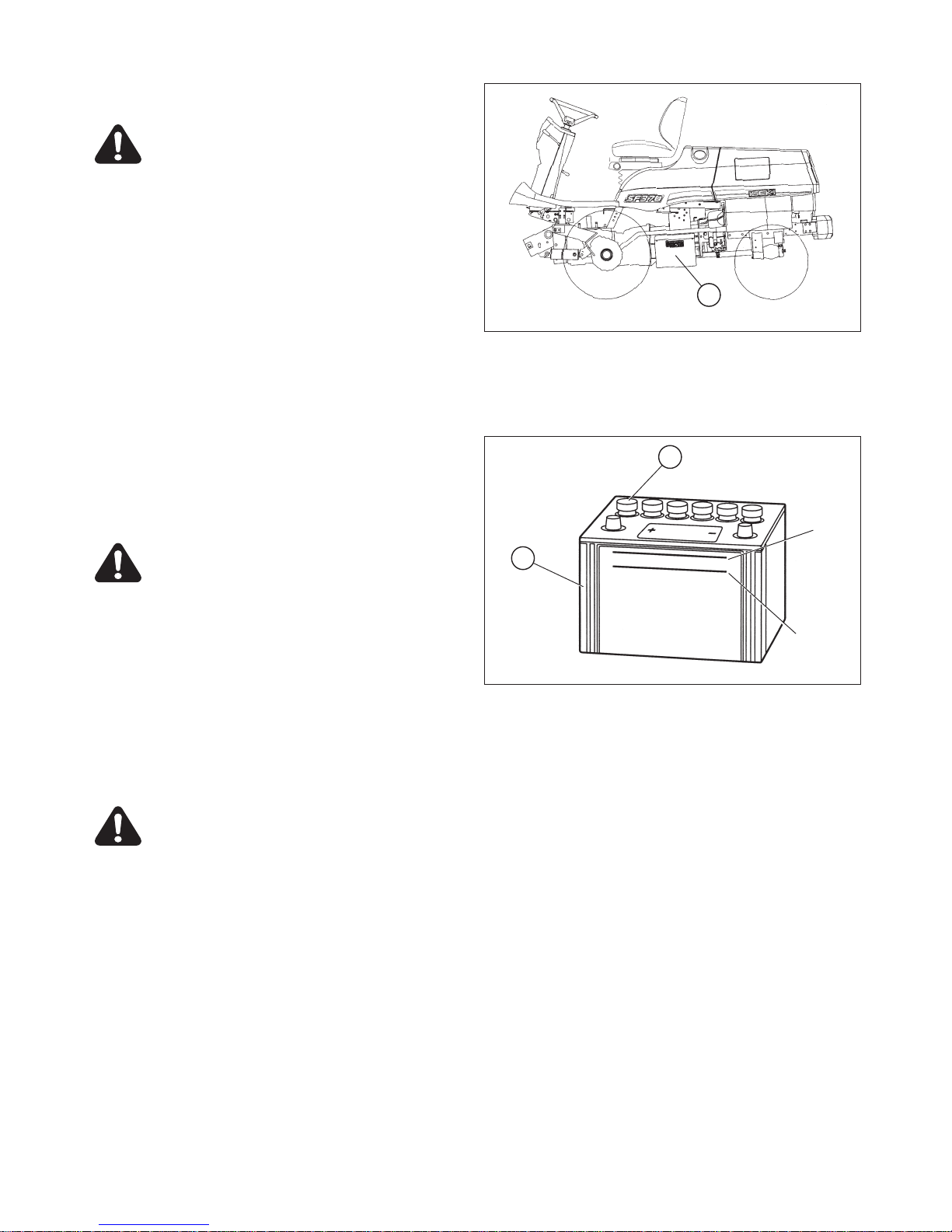
CHAPTER 8. MAINTENANCE
59
16. BATTERY
DANGER:
• The battery generates very explosive
gases, so avoid smoking and keep sparks
and open flames away from the battery.
Charging the battery should be done in a
place well ventilated to disperse explosive
gases as quickly as possible.
• Battery electrolyte is very corrosive and
will cause burns, so if it splashes on skin
or clothes, wash it off immediately. If acid
contacts eyes, flush immediately with
clean water and get medical attention.
• When using booster cables, take sufficient
safety measures.
INSPECTION OF ELECTROLYTE LEVEL
The battery,1, is installed on the middle of the left hand
side of the front mower. Check to see if the electrolyte
level is between the upper and lower limits.
When the level is near to the lower limit or below, raise the
level with distilled water to the upper limit.
WARNING:
Never attempt to keep on using or charging
the battery with a electrolyte level lower than
the limit, or the battery may explode or its
service life be shortened due to deterioration
inside the casing.
IMPORTANT: The electrolyte level should always be
kept between the upper and lower limits. A
too high level will cause the electrolyte to
overflow and corrode other parts.
HANDLING OF THE BATTERY
WARNING:
• Be sure to connect the battery terminals
correctly.
• The wiring from the battery should be kept
clean and connectors tight. Dirty or loose
wiring may cause a fire.
• When disconnecting the battery, disconnect
the negative terminal first and vice versa
when connecting.
• When replacing the battery, use a battery of
the same capacity as that of the current on
(80D 26R).
a. As atmospheric temperature lowers, the performance
of the battery also lowers. Consequently the battery
should be serviced with special care in wintertime.
(1) Battery
(1) Battery A: Upper limit
(2) Filler plug B: Lower limit
1
FIG. 93
1
2
A
B
FIG. 94

SF310,370
60
b. As the battery discharges even when it is not used, it
should be charged every or every other month at the
maximum.
c. When the front mower is not used for a long time,
remove the battery from the front mower and store it in
a place dry and shaded from direct sunshine.
IMPORTANT: Avoid quick charge of battery. Or it will
shorten the service life of the battery.
IMPORTANT: When storing front mower for long period
without operation, self discharge of battery
will happen (especially in winter). If the
front mower is stored for more than 1
month, the battery minus terminal should
be disconnected. When operating for the
first time or after long term storage, check
if the battery charge level is enough. (If
measurement of battery voltage is available, check if the voltage is more than
12.5V.) When the front mower is stored
more than 6 months, charge the battery.
IMPORTANT: Don’t throw away the battery to the gar-
bage can. Recycle it with observing the
law of your community.
17. TIRE PRESSURE (INFLATION)
Improper tire pressure causes the tires to wear abnor-
mally and affects the front mower performance. Too
high pressure causes the front mower to bounce too
much and too low pressure increases travelling resistance, which leads to power loss.
Tire pressure should be checked everyday.
WARNING:
• Tire inflation should be set to the values specified in this manual. Excessive inflation may
cause certain types to explode, which may
result in serious accidents.
• Never use a tire with a cut or crack which
reaches tire cords as such a tire may explode.
• When a tire, tube, or rim is required for
replacement, ask your dealer. Such operation
should be done by a mechanic trained especially for tire handling.
• Insufficient pressure in the tires causes
uneven tire friction that can shorten tire lifetime.
FIG. 95
Standard Front
Rear
Wide Front
Rear
Tire size
23X10.50-12
20X8.00-10
26X12.00-12
22X8.50-12
Pressure
1.4 kgf•cm
2
1.6 kgf•cm
2
1.4 kgf•cm
2
1.6 kgf•cm
2

CHAPTER 8. MAINTENANCE
61
18. STEERING WHEEL (TOE-IN)
Start the engine and turn the steering wheel lightly in both
directions to check to see the wheel turns smoothly.
Make sure that the tire toe-in is properly set. Improper toein causes unstable steering of the front mower: the front
mower has a tendency to turn in one direction, right or left
or the steering wheel turns unexpectedly.
Proper toe-in: A-B = 1 to 10mm (0 to 0.4 in.)
19. ENGINE OIL REPLACEMENT
IMPORTANT:
• The engine oil should be replaced with fresh oil in
accordance with operation hours. If not, overly used oil
will cause engine troubles.
• The first replacement should be done after the initial
50 hours of operation and then after every 150 hours
of operation.
When replacing engine oil, place the front mower on level,
hard ground. The engine oil drain is located bottom of the
engine oil pan, which is accessible from the left side of the
front mower. SF370 has 2 drains on both left and right side.
a. Place a tray or the like under the oil drain to receive
drained oil.
b. The engine should be warmed up for 10 minutes or so
ahead of time to heat the oil to lower its viscosity for
compete drainage.
c. Remove the drain plug,1, allowing the used oil drain
out completely.
d. When the used oil has drained out completely, screw
the drain plug back in securely.
e. Remove the oil filler cap,3, at the right sidewall of
engine and pour in fresh engine oil through the oil filler.
Be sure to use oil recommended by ISEKI. Refer to
“2. ENGINE OIL LEVEL” .
f. After engine oil replacement, start the engine and let it
idle for a while.
g. Then stop it and wait for a while until the engine oil
comes down into the oil pan, 2. Now check the oil level
to check to see if it is at the upper limit or not. When
the level is low, replenish until the level reaches the
upper limit.
IMPORTANT: Never fill over the upper limit, or it may
cause engine trouble.
h. Make sure that there is no oil leakage through the
drain plug and oil filter.
(1) Drain plug (2) Oil pan
(3) Engine oil filler
1
2
FIG. 97
Engine oil capacity
SF310
SF370
2.8 litres (0.6 imp.gal)
3.3 litres (0.7 imp.gal)
3
FIG. 98
FIG. 96

SF310,370
62
20. ENGINE OIL FILTER
IMPORTANT:
• The engine oil filter should be replaced after the initial
50 hours of operation and then after every 300 hours
of operation.
• It is recommended to ask your dealer to replace the
engine oil filter, because this operation requires a special tool. But when there is no alternative but to replace
the filter by yourself, observe following instructions.
The engine oil filter,1, is located on the left-hand wall of
the cylinder block.
a. Drain engine oil completely following the instructions of
“9. ENGINE OIL REPLACEMENT.”
b. Place some rags under the engine oil filter to receive
dripping oil when the filter is replaced.
c. Loosen the filter using a filter spanner and remove it.
d. Install a new filter with the O-ring lubricated with fresh
engine oil. Screw in the filter until its packing comes
into contact with the sealing surface of the engine and
then tighten it by a 2/3 turn with the filter spanner.
e. Pour the drained oil back in referring to “9. ENGINE
OIL REPLACEMENT.”
21. TRANSMISSION OIL REPLACEMENT
IMPORTANT:
• The transmission oil should be replaced after the initial
50 hours of operation and then after every 300 hours
of operation.
• It is recommended to ask your dealer to replace the
transmission oil, because this operation also requires
replacement of the hydraulic oil filter and washing or
replacement of the suction filter.
But when there is no alternative but to replace the filter
by yourself, observe the following instructions.
The transmission oil drain is located under the center of
transmission case.
a. Place a tray under the drain plug,1.
b. Remove the drain plug and let the oil drain out.
c. Reinstall the drain plug and tighten it securely.
d. Pour fresh transmission oil through the oil filler on top
of the transmission case until the level reaches the
upper limit on the level gauge (dipstick) in referring to
“3. TRANSMISSION OIL LEVEL”.
(1) Engine oil filter
(1) Drain plug
FIG. 99
FIG. 100

CHAPTER 8. MAINTENANCE
63
e. After replacement, start the engine and let it idle for a
while. Then stop it and wait for a while until the oil
comes down into the oil pan.
Now check the oil level to check to see if it is at the
upper limit or not. When the level is low, replenish until
the level reaches the upper limit.
f. Make sure that there is no oil leaking through the oil fil-
ter, suction filter, rubber hoses, or drain plug.
22. HYDRAULIC OIL FILTER
IMPORTANT:
• The hydraulic oil filter should be replaced after the initial 50 hours of operation and then after every 300
hours of operation. It should also changed every time
the transmission oil is replaced.
• It is recommended to ask your dealer to replace the
hydraulic oil filter. But when there is no alternative but
to replace the filter by yourself, observe the following
instructions.
The hydraulic oil filter,1, is located center of the right-hand
side of the front mower.
a. After the transmission oil has drained out completely,
remove the filter using the filter spanner.
When removing the filter, a small amount of oil may
spill, so place waste cloth under the filter to receive
spilt oil.
b. Apply thin coat of oil to the O-ring of the new oil filter
cartridge ahead of time. Then install the filter. Screw in
the filter by hand until the rubber packing comes into
contact with the sealing surface, and then screw in it
by a 2/3 turn with the filter spanner.
Oil: SHELL DONAX TD oil
23. SUCTION FILTER
IMPORTANT:
• The suction oil filter should be cleaned after the initial
50 hours of operation and then after every 200 hours
of operation. It should also cleaned every time the
transmission oil is replaced.
• It is recommended to ask your dealer to replace the
suction filter. But when there is no alternative but to
replace the filter by yourself, observe the following
instructions.
The suction filter,1, is located bottom left of the transmission case.
(1) Hydraulic oil filter
(2) Rubber hose (3) Suction pipe
(4) Hose clips
1
FIG. 101
Transmission oil
Capacity
SHELL DONAX TD
17 liters (3.7 imp-gal.)
2 4
3
FIG. 102

SF310,370
64
a. After draining out the transmission oil, detach the rub-
ber hose,2, connecting the suction filter and the suction pipe,3, by removing the hose clips,4.
b. Draw the suction filter out of the transmission case.
c. Wash the filter in fresh cleansing oil.
IMPORTANT: The inside of the removed hose should
also be cleaned.
d. Install the cleaned suction filter into the transmission
case, taking care not to deform the O-ring,5.
e. Connect the rubber hose and tighten both ends with
the hose clips.
IMPORTANT:
• If a suction filter is found damaged during washing, it
should be replaced whit a new one
24. REDUCTION GEAR CASE OIL REPLACEMENT
IMPORTANT:
• The oil in the reduction gear case should be replaced
after the initial 50 hours of operation and then after
every 300 hours of operation.
The reduction gear case drain is located on the bottom of
the case on the left-hand side of the front mower.
a. Place a tray under the drain plug,1.
b. Remove the drain plug using a spanner or wrench.
c. After the oil has drained out completely, wrap the
threads of the drain plug with sealing tape and screw
the drain plug back in securely.
IMPORTANT: Before re-installing the level plug, wrap the
threads of the plug with sealing tape. If
not, oil may leak out through the plug.
d. Pour fresh gear oil through the filler located below the
fuel tank in referring to “4. REDUCATION GEAR CASE
OIL LEVEL”.
Oil Gear oil SAE 80
Capacity 0.7 litre (0.15 lmp. gal. )
(1) Suction filter (5) O-ring
(1) Drain plug (2) Reduction gear case
(3) Engine oil pan
1
5
FIG. 103
1
2
3
FIG. 104

CHAPTER 8. MAINTENANCE
65
25. REAR AXLE OIL REPLACEMENT
IMPORTANT:
• The rear axle oil should be replaced after the initial 50
hours of operation and after 600 hours of operation.
The rear axle drain is located on the bottom of the right
and left gear cases.
a. Place a tray under the drain plug,1.
b. Remove the drain plug using a spanner or wrench.
c. Let all oil drain out from both the gear cases.
d. Wrap the threads of the drain plug with sealing tape
and screw it back in securely.
IMPORTANT: Before re-installing the level plug, wrap the
threads of the plug with sealing tape. If
not, oil may leaks through the plug.
e. Pour fresh gear oil through the oil filler on the top of
the left-hand rear axle in referring to “5. REAR AXLE
OIL LEVEL”.
Oil Gear oil SAE 80
Capacity 4.1 litres (0.9 lmp. gal. )
26. AIR-INT AKE OPENINGS
IMPORTANT:
• Air-intake openings clogged with dust or dirt causes
overheating of the engine due to deteriorated cooling
efficiency of the radiator. The air-intake screens should
be checked for clogging everyday before operation.
• When mowing dead grass or operating under extremely dusty conditions, check the air-intake openings several times a day to avoid clogging.
• Hood screens (LH, RH and rear),1.
• Under cover screens (LH, RH and rear),2.
Open the engine hood and dust the screens and net
using a piece of cloth or the like.
• Plate (base) screen,3
Open the engine hood and dust the screen of the plate
(base) under the fuel tank from inside and outside
using a piece of cloth or the like.
(1) Drain plug (2) Gear case
(3) Rear wheel
(1) Hood screen (2) Under cover screen
(3) Plate (base) screen
3
1
2
FIG. 105
2
1
3
FIG. 106

SF310,370
66
27. RADIATOR
IMPORTANT:
• The radiator screen and radiator clogged with dust or
dirt causes overheating of the engine due to deteriorated cooling efficiency of the radiator.
The radiator and radiator screen should be checked for
clogging everyday before operation.
• When mowing dead grass or operating under extremely dusty conditions, check the radiator screen and radiator several times a day to avoid clogging.
The radiator,1, is located behind the engine and the
radiator screen,2, is located between cooling fan and
the radiator.
a. The radiator screen is held on the left side of the radia-
tor with two wing blots. Remove the wing bolts and
draw out the radiator screen.
b. Dust off the radiator screen with a soft brush.
c. The clogged radiator fins should be cleaned by apply-
ing compressed air or water from both sides alternatively.
d. Re-install the radiator screen and tighten the wing
bolts.
IMPORTANT:
• Avoid using excessively compressed air or water,
which may deform the cooling fan blades.
• Avoid applying water directly to the wiring and electric
apparatus.
• After washing the radiator using water from a tap, let it
dry by itself.
28. COOLANT REPLACEMENT
WARNING: Never attempt to remove the radiator cap during or just after operation, or
pressurized vapor and hot water will gush
out, which may cause burns. So wait until the
engine cools down sufficiently.
The drain plug of the engine coolant is located under the
reserve tank of the left side of the engine.
a. Place a coolant receiver under the drain plug,1.
b. Remove the radiator cap,2, and the drain plug to let all
coolant drain out of the radiator and engine cylinder
block.
c. When all coolant completely drained out, wash the
inside of the radiator and tighten the drain plug securely .
(1) Radiator (2) Radiator screen
(1) Drain plug
2 1
FIG. 107
1
FIG. 108

CHAPTER 8. MAINTENANCE
67
d. Pour the coolant which has a specified antifreeze con-
centration until it starts overflowing through the coolant
filler. Retighten the radiator cap securely.
WARNING: Be sure to tighten the radiator cap
securely, or boiling coolant may shoot out,
which is very dangerous.
IMPORTANT:
• Frozen coolant may damage the engine.
• Mixing ratio of water and antifreeze is different by antifreeze manufacturers and atmospherc temperatures.
• Water and anifreeze should be blended sufficiently
ahead of time.
e. After filling, start the engine and let it idle for 5 minutes
or so. Then check the coolant level. If the level is low,
replenish the reserve tank with coolant in referring to
“6. COOLANT LEVEL”.
IMPORTANT:
• Never attempt to run the engine without coolant, or the
engine will seize, leading to its complete damage.
29. FUSES AND WIRING
The fuse box,1, is located rearward inside the step
floor.
CAUTION:
• Never replace blown fuses or slow-blow
fuse with wire.
(2) Radiator cap (3) Radiator
(1) Fuse box
Coolant capacity
Radiator
Reserve tank
5.2 litres (1.1 lmp. gal.)
1.1 litres (0.2 lmp. gal.)
1
FIG. 110
2
3
FIG. 109
Ref
A
B
C
D
E
F
Fuse
capacity
15A
15A
10A
15A
10A
3A
Application
Hazard and
Stop lamps(G type)
Option DC12V
(B:Battery direct)
Meter and
Monitor lamps
Flashing lamps
(G type)
Option DC12V
(AC: Accessory)
Fuel pump
Ref
G
H
I
J
K
L
Fuse
capacity
15A
5A
10A
10A
10A
Application
Head lamps
(G type)
Horn
Engine start
parts
PTO control
parts
Work lamp
(and position lamps)
Spare

SF310,370
68
IMPORTANT:
• When a fuse or a slow-blow fuse is blown, be sure to
locate the trouble and correct it. When the cause is not
clear, consult your dealers.
• Be sure to use specified fuses. Larger-capacity fuses
will cause burn-out of electric accessories and wiring.
• When a slow-blow fuse has been burnt out, use genuine slow-blow fuse.
WARNING:
• Damaged wire covers should be mended
with insulation tape immediately.
CAUTION:
• The wiring of the front mower should be
checked every year at your dealers to avoid
electrical fires.
• Grass and dust around the battery, wiring,
muffler and engine should be removed.
Otherwise they may catch fire.
IMPORTANT:
• When a wire harness has come off its clamp, it should
be re-clamped immediately.
30. HYDRAULIC SYSTEM PARTS
When hydraulic system parts such as the HST unit,
hydraulic pump, control valve, hydraulic cylinder, piping, etc. are required to be adjusted or repaired, consult your ISEKI dealers. Users are advised not to
adjust or repair hydraulic system parts by themselves.
31. SAFETY SWITCHES
Safety devices are installed for safe operation. Make
certain that each device works properly before operation following the next procedures.
CAUTION: When the engine does not start
due to a defective safety switch or does not
stop when the operator has left the operator’s
seat, consult your dealer at once without fail.
(E6 type) The engine keeps running even
when the operator has left the operator ’s
seat, provided that the PTO switch is in the
OF F (
) position and the parking brake is
applied.
INSPECTION 1
a. Be seated in the operator’s seat.
b. Turn the PTO switch to the OFF ( ) position.
c. Turn the key switch to the START ( ) position without
depressing the master brake pedal.
Make sure that the engine is not cranked.
INSPECTION 2
a. Be seated in the operator’s seat.
b. Turn the PTO switch to the ON (
) position.
c. Depress the master brake pedal fully.
d. Turn the key switch to the START ( ) position.
Make sure that the engine is not cranked
INSPECTION 3
a. Be seated in the operator’s seat.
b. Turn the PTO switch to the OFF ( ) position.
c. Depress the master brake pedal fully.
d. Turn the key switch to the START ( ) position.
Make sure that the engine is cranked and started.
e. Leave from the operator’s seat.
Make sure that the engine should stop.
(E6 type)
f. Restart the engine by repeating above a. to d..
g. Apply the parking brake.
h. Leave from the operator’s seat.
Make sure that the engine keeps running.
INSPECTION 4 (F type)
a. Open the engine hood.
b. Be seated in the operator’s seat.
c. Turn the PTO switch to the OFF ( ) position.
d. Depress the master brake pedal fully.
e. Turn the key switch to the START ( ) position.
Make sure that the engine is not cranked and started.
Slow - blow fuse
50A
40A
Parts code
1614-690-202-0
1650-650-222-0

CHAPTER 8. MAINTENANCE
69
32. FILLING DIAGRAM
• Use oil of better than class CC. • Use ISEKI’s recommended oil.
9
6 1 4
2
2 753
8
4
FIG. 111
Lubrication oil
Coolant
Grease
Fuel
Ref. NO. Filling points Lubricants
Quantity: liter (IMP gal. )
SF310 SF370
1
2
3
4
5
6
7
8
9
Engine
Radiator
Reserve tank
Transmission case
Center pivot (2 points)
Fuel tank
Reduction gear case
Rear axle
Power steering cylinder end
HST pedal pivot
Other lubrication points marked with
yellow paint
Engine oil
Coolant
(Soft water + antifreeze)
HST oil (SHELL DONAX TD)
Grease
Diesel fuel
Gear oil (SAE 80)
Grease
Gear oil or grease
2.8 (0.6) 3.3 (0.7)
5.2 (1.1)
1.1 (0.2)
17.0 (3.7)
As required
48.0 (12.7)
0.7 (0.15)
4.1 (0.9)
As required
As required

SF310,370
70
33. PERIODICAL INSPECTION TABLE
:Inspection, replenishment, and adjustment :Cleaning and washing
:Replacement :Consult your dealer.
Check points
Engine oil
Air cleaner
Engine coolant
Fuel
Fuel strainer
Fan belt
Electrolyte level
Engine oil filter
Transmission oil
Transmission oil filter
Suction filter
Master brake pedal play
Tire pressure
Reduction gear case
oil
Wheel tightening bolts
Grease-up
Radiator screen
Radiator
Electrical apparatus
Safety switches
Air intake openings
Bolts and nuts
Rubber pipes
Pre-
operation
Inspection and servicing intervals
hours of operation
50
100
150
200
250
300
350
400
Intervals
after that
Replace after initial 50 hr
and then every 150 hr.
Clean after every 50hr.
Replace every 2 year.
Clean after every 100hr.
Replace element after every
300hr or once a year.
Inspect after every 50hr.
Replace after initial 50hr.
Replace after every 300hr.
Replace after initial 50hr.
Replace after every 300hr..
Replace after initial 50hr.
Replace after every 300hr.
Replace after initial 50hr.
Clean after every 200hr.
Inject grease after every 50hr.
Adjust after every 300hr.
Check after every 100hr.
Judgement
criteria
Maintain the specified level.
Maintain the specified level.
Keep fuel tank always full.
There should be no dust or
water in filter.
10mm (0.4 in.) deflection
Maintain the specified level
Maintain the specified level.
20 to 30 mm (0.8 to 1.2in.)
Front: 1.4 kgf / cm2
Rear: 1.6 / 1.5 (wide) kgf / cm2
There should be no loose.
There should be no clogging.
Engine hood and rear
cover
There should be no clogging.
There should be no clogging.
All should work properly.
All should work properly.
There should be no clogging
There should be no loose ones.
Ref.
page
49
60
53
52
65
52
53
54
58
61
50
61
62
62
55
59
Replace after initial 50hr.
and then every 300hr.
Maintain the specified level.
50
63
Rear axle oil
Replace after initial 50hr.
and then every 600hr.
Maintain the specified level.
51
64
64
Steering wheel
Inspect after every 300hr.
There should be no
abnormality.
59
57
Toe-in
0 to 10 mm (0 to 0.4 in. ) 60
68
65
65
66
67
64
—
—
IMPORTANT:
• Above mentioned service intervals should be regard as reference creteria. If working conditions are harder, earlier
service is recommended.
• When special technique or special tools is required, consult your dealers.
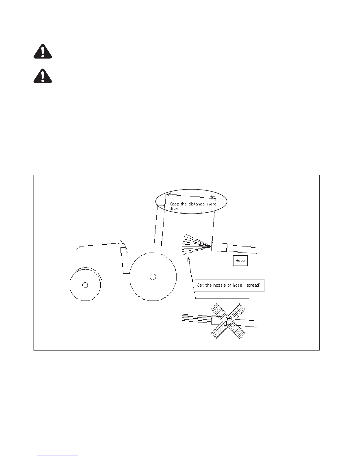
CHAPTER 8. MAINTENANCE
71
34. WASHING THE MACHINE
CAUTION: If you use high pressure washer, be sure to use in accordance with operator’s manual and
safety label of washer. In case of irregular using. It may cause that personal injury and damaging of
machine.
CAUTION: Set the nozzle of hose ‘spread’ and keep the distance more than 60cm in order to avoid
damaging of machine. Especially, be care for not to hit the water to electrical parts and label.
Unsuitable washing may cause that
1. Fire by short circuit and damaging of electrical parts.
2. Flowing of oil by damaging of hydraulic hose.
3. Damaging and accident of machine.
(1) Coming off of label.
(2) Accident of electrical parts, engine, radiator, and interior.
(3) Damaging of lubber parts (tyre, seal) and resin parts.
(4) Coming off of paint.
60cm.
FIG. 112

SF310,370
72
35. MAJOR CONSUMABLES LIST
1
2
3
5
6
8
9
11
10
124
7
1 AIR CLEANER
ELEMENT ASSY
89SLOW BLOW FUSE 50A
SLOW BLOW FUSE 40A
2 FUEL FILTER 10 HEADLAMP
BULB/12V25/25W
3 ENGINE OIL FILTER
CARTRIDGE
11 MONITOR LAMP
BULB
4
5
6
7
FUSE BLADE 32V05A
FUSE BLADE 32V03A
FUSE BLADE 32V10A
FUSE BLADE 32V15A
12 BLADE
FIG. 113

CHAPTER 8. MAINTENANCE
73
REF PARTS NAME PARTS CODE
1 ELEMENT ASSY 1650-104-203-10
2 FILTER/FUEL 1729-111-006-10
3
CARTRIDGE/OIL FILTER (for SF310) 6213-240-002-20
CARTRIDGE/OIL FILTER (for SF370) 6213-240-005-10
4 FUSE/BLADE/32V05A 1560-664-264-00
5 FUSE/BLADE/32V03A 1575-623-009-00
6 FUSE/BLADE/32V10A 1575-623-010-00
7 FUSE/BLADE/32V15A 1575-623-011-00
8 FUSE/SLOWBLOW/50A 1614-690-202-00
9 FUSE/SLOWBLOW/40A 1650-650-222-00
10 BULB/12V25/25W 1444-621-251-00
11 BULB 3650-270-214-00
12
BLADE/60x528/C (for SSM60) 8654-306-006-10
BLADE/60x630/C (for SSM72) 8655-306-003-10

74
SF310,370
74
DAILY AND SHORT TERM STORAGE
a. Clean the front mower.
IMPORTANT: When washing the front mower, avoid
applying compressed water directly to the
electric apparatus, oil and fuel fillers.
Remove the starter key and cap the switch
key hole to prevent short circuits.
b. Lower the mower deck on the ground.
CAUTION: A lifted up mower deck may go down
unexpectedly if the lift lever is manipulated by
children or unauthorised people, which may
lead to serious accidents.
c. The front mower should be stored indoors if possible.
When it has to be left outdoors, cover it with tarpaulin
or the like.
WARNING: When covering the front mower
with tarpaulin, wait until heated components
such as the engine, muffler, etc. have cooled
down completely. Otherwise a fire may be
caused.
d. When the ambient temperature is very low, remove the
battery and store it in a warm shaded dry place. This
will contribute greatly to easy starting of the engine the
following morning.
CAUTION: Remove the starter key without fail
before storage.
LONG TERM STORAGE
a. Clean the front mower and correct all troubles such as
repair, replacement of defective parts, readjustment,
etc.
b. Top up the fuel tank and close the fuel cock.
c. Replace the engine oil with new and let the engine idle
for about 5 minutes to lubricate every part sufficiently.
d. Lubricate all lubrication points.
e. Grease up all greasing points.
f. Check bolts and nuts for looseness and re-tighten loose
ones.
g. Inflate each tire a little higher than specified.
h. Dismount the mower deck or lower it to the ground.
CAUTION: A lifted up mower deck may go
down unexpectedly if the lift lever is manipulated children or unauthorised people, which
may lead to serious accidents.
i. Cover the front mower with tarpaulin or the like in order
to protect it from rainfall and dust.
WARNING: When covering the front mower
with tarpaulin, wait until heated components
such as the engine, muffler, etc. have cooled
down completely. Otherwise a fire may be
caused.
j. Remove the battery, charge it, and store it in a shaded
dry place with no access to children.
k. Charge the battery completely every month.
CAUTION:Remove the starter key without fail
before storage.
OPERATION AFTER A LONG TIME OF STORAGE
a. Perform the pre-operation inspection without fail.
b. Let the engine idle for about 30 minutes before apply-
ing any load, to ensure maximum engine performance
and service life.
WARNING: Provide sufficient ventilation for
exhaust fumes when starting the engine,
because such fumes are very poisonous.
CHAPTER 9. STORAGE

CHAPTER 10. TROUBLESHOOTING
75
1. ENGINE
CHAPTER 10. TROUBLESHOO TING
Troubles
• Starter motor does not work.
• Starter motor works but
engine does not start.
• Engine runs at irregular
speeds or stalls soon.
• Engine knocks.
Presumable causes
• Master brake pedal is not depressed.
• PTO switch is not in OFF ( ) position.
• Battery is not charged fully.
• Battery terminals are poorly connected.
• Defective internal wiring in connector
• Defective safety switch of seat
• Broken starter switch
• Broken starter motor
• Cock of fuel strainer is closed.
• No fuel
• Water trapped in fuel
• Air trapped in fuel
• Clogged fuel hoses
• Clogged fuel strainer
• Slow cranking speed
• Insufficient pre-heating
• Throttle lever is in low speed ( ) position.
• Too high engine oil viscosity
• Clogged air-cleaner
• Insufficient compression
• Incorrect injection timing
• Clogged injection nozzles
• The engine hood is not closed.
• Air trapped in fuel system
• Improper earthing
• Clogged fuel strainer
• Leaking fuel system
• Defective injection pump
• Too low engine oil level
• Engine is overheated.
• Coolant temperature does not rise.
• Defective injection pump
Remedies
• Depress it fully.
• Turn it to OFF position.
• Charge it.
• Clean the terminal posts and connect them securely.
• Rewire.
• Consult your dealer.
• Consult your dealer.
• Consult your dealer.
• Open it.
• Replenish with fuel.
• Drain trapped water from fuel
strainer.
• Bleed injection pump.
• Clean fuel hose inside.
• Wash or replace it.
• Charge battery.
• Preheat for specified time.
• Shift it to high speed position.
• Replace it with one of lower viscosity.
• Clean element.
• Consult your dealer.
• Consult your dealer.
• Consult your dealer.
• Close the engine food securely.
• Locate cause of air-trapping and
bleed system of air.
• Polish earthing points and re-connect.
• Clean or replace it.
• Tighten joints securely or replace
damaged hose.
• Consult your dealer.
• Add oil to upper limit.
• Consult your dealer.
• Consult your dealer.
• Consult your dealer.

76
SF310,370
76
Troubles
• Engine knocks.
• Engine output is insufficient.
• Engine is overheated.
• Oil pressure lamp is blinking
• Exhaust fumes are white.
• Exhaust fumes are black.
Presumable causes
• Defective injection nozzles
• Incorrect valve clearances
• No fuel
• Clogged air cleaner
• Engine is overloaded.
• Improper fuel
• Engine is overheated.
• Throttle lever is not in the high speed ( )
position.
• Insufficient compression
• Improper valve clearances
• Defective injection pump
• Defective injection nozzles
• Incorrect injection timing
• Low engine coolant level
• Loose fan belt
• Clogged radiator fins and screen
• Low engine oil level
• Clogged air-intake openings
• Engine is overloaded.
• Clogged engine oil filter
• Low engine oil level
• Low engine oil viscosity
• Clogged engine oil filter
• Defective oil pump
• Defective oil pressure switch
• Clogged air cleaner
• Too high engine oil level
• Insufficient fuel injection
• Defective fuel
• Clogged intake system
Remedies
• Consult your dealer.
• Consult your dealer.
• Supply with fuel.
• Clean element.
• Raise cutting height or slow down
front mower.
• Use proper diesel fuel.
• Cool down engine.
• Shift it there securely.
• Consult your dealer.
• Consult your dealer.
• Consult your dealer.
• Consult your dealer.
• Consult your dealer.
• Replenish
• Tighten it properly.
• Clean them.
• Replenish engine oil to upper limit.
• Clean air-intake.
• Raise cutting height or slow down
front mower.
• Ask your dealer to replace it with a
new one.
• Add oil to upper limit.
• Replace with oil of higher viscosity.
• Ask your dealer to replace it with a
new one.
• Consult your dealer.
• Consult your dealer.
• Clean element.
• Drain oil to upper limit.
• Consult your dealer.
• Use proper fuel.
• Clean air cleaner element.

CHAPTER 10. TROUBLESHOOTING
77
2. BRAKE SYSTEM
3. LIFT SYSTEM
Troubles Presumable causes Remedies
• Exhaust fumes are black. • Clogged exhaust system
• Excessive fuel injection rate
• Insufficient injection nozzle pressure
• Incorrect injection timing
• Check muffler for clogging and
clean it.
• Consult your dealer.
• Consult your dealer.
• Consult your dealer.
• Engine stalls at low speed. • Defective injection pump
• Defective injection nozzles
• Incorrect valve clearance
• Consult your dealer.
• Consult your dealer.
• Consult your dealer.
• Engine races. • Clogged governor
• Engine oil leaks into cylinder.
• Consult your dealer.
• Consult your dealer.
• Excessive fuel consumption • Defective fuel
• Clogged air-intake line
• Engine is overloaded.
• Fuel leaks
• Incorrect valve clearances
• Use proper fuel.
• Clean air cleaner and air-intake
hose inside.
• Raise cutting height or slow down
front mower.
• Replace damaged parts with new
ones and tighten joints securely.
• Consult your dealer.
• Charge lamp is blinking.
• Defective wiring
• Lower electrolyte level
• Loose fan belt
• Defective alternator
• Defective regulator
• Correct loose, dirty, short, improperly earthed terminals.
• Replenish with distilled water to
upper limit.
• Tighten it properly.
• Consult your dealer.
• Consult your dealer.
• Defective braking effect or
uneven braking
• Excessive master brake pedal play
• Worn brake linings
• Improperly adjusted brake rods
• Correct pedal play.
• Consult your dealer.
• Correct rod length.
• Master brake pedal does not
return smoothly.
• Fatigued or broken return spring
• Defective lubrication of linkage
• Replace it.
• Lubricate lubrication points.
• Lift does not rise.
• Low transmission oil level
• Air trapped inside hydraulic piping
• Fill up to upper limit.
• Consult your dealer.

78
SF310,370
78
Troubles Presumable causes Remedies
• Lift does not rise. • Clogged hydraulic oil filter
• Clogged suction filter
• Defective hydraulic pump
• Defective control valve
• Defective hydraulic cylinder
• Consult your dealer.
• Consult your dealer.
• Consult your dealer.
• Consult your dealer.
• Consult your dealer.
• Lift does not lower. • Lift lock is engaged
• Defective control valve
• Seized lift shaft
• Release it.
• Consult your dealer.
• Consult your dealer.
4. STEERING SYSTEM
5. HST (Hydrostatic transmission)
• Steering wheel is very heavy
to turn.
• Low tire pressure
• Low transmission oil level
• Air trapped inside hydraulic piping
• Clogged hydraulic oil filter
• Clogged suction filter
• Defective hydraulic pump
• Defective power-steering unit
• Correct it as specified.
• Fill up to upper limit.
• Consult your dealer.
• Consult your dealer.
• Consult your dealer.
• Consult your dealer.
• Consult your dealer.
• Steering wheel has a tendency
to turn in one direction.
• Uneven tire inflation
• Improper toe-in
• Excessively worn tie-rod ends
• Inflate both front and rear tires to
specified pressure.
• Consult your dealer.
• Consult your dealer.
•
Excessive steering wheel play
• Excessively worn tie-rod ends
•
Excessively worn steering wheel column shaft
• Defective power-steering unit
• Consult your dealer.
• Consult your dealer.
• Consult your dealer.
• Front mower does not start
travelling.
• Parking brake is applied.
• Too low engine speed
• Low transmission oil level
• Air trapped inside hydraulic piping
• Improperly adjusted HST pedals
• Clogged hydraulic oil filter
• Clogged suction filter
• Defective HST unit
• Release it.
• Accelerate engine.
• Fill to upper limit.
• Consult your dealer.
• Consult your dealer.
• Consult your dealer.
• Consult your dealer.
• Consult your dealer.
• Front mower creeps without
HST pedals being operated
• Stuck neutral arm
• Incorrect neutral point of HST
• Improperly positioned neutral arm
• Defective HST unit
• Lubricate.
• Consult your dealer.
• Consult your dealer.
• Consult your dealer.

CHAPTER 10. TROUBLESHOOTING
79
Troubles
• Battery is not charged. • Melted slow-blow fuse
• Defective wiring
• Loose fan belt
• Defective battery
• Defective alternator
• Locate and repair cause of trouble,
and install a new slow-blow fuse.
• Check wiring for loose terminals
and earth, and short circuit. Repair
defective parts.
• Tighten belt as specified.
• Correct loose terminals, corroded
parts, and electrolyte level.
Otherwise, install a new battery.
• Consult your dealer.
• Head lamps are dim. • Low battery capacity
• Defective contact of switch or wiring
• Charge battery.
• Clean contact points and earthing
point, and tighten them.
• Head lamps do not light up. • Burnt-out bulb
• Blown fuse
• Defective contact
• Replace the burnt-out bulb.
• Check the wiring and replace the
blown fuse with a new one.
• Clean each contact and tighten
securely.
• Monitor lamps do not
light up.
• Defective contact • Re-connect connector.
• Fuel pump does not work. • Blown fuse
• Defective fuel pump
• Check the wiring and replace the
blown fuse with a new one.
• Consult your dealer.
• Fuel cut-off solenoid does not
work.
• Blown fuse
• Defective solenoid
• Check the wiring and replace the
blown fuse with a new one.
• Consult your dealer.
6. ELECTRICAL ACCESSORIES
Presumable causes Remedies

80
SF310,370
SF310
Max. 4.06 m/s
2
Max. 0.77 m/s
2
105
2500
2840 2385 2840
SF370+SSM60
2385
NOISE:
Sound power level dB(A)
Weighted root mean square acceleration less than value
to which the arms are subjected
Weighted root mean square acceleration less than value
to which the body is subjected
Speed of rotation of the engine
Test code
Speed of rotation Engine min
-1
(rpm)
Blade min
-1
(rpm)
Test code
SF310+SSM60 SF310+SSM72 SF370+SSM72
2750 min-1(rpm)
SF370
2800 min-1(rpm)
ISO 5395-1
2000/14/EC amended by 2005/88/EC
VIBRATION:
NOISE & VIBRATION

81

82
SF310,370

83

84
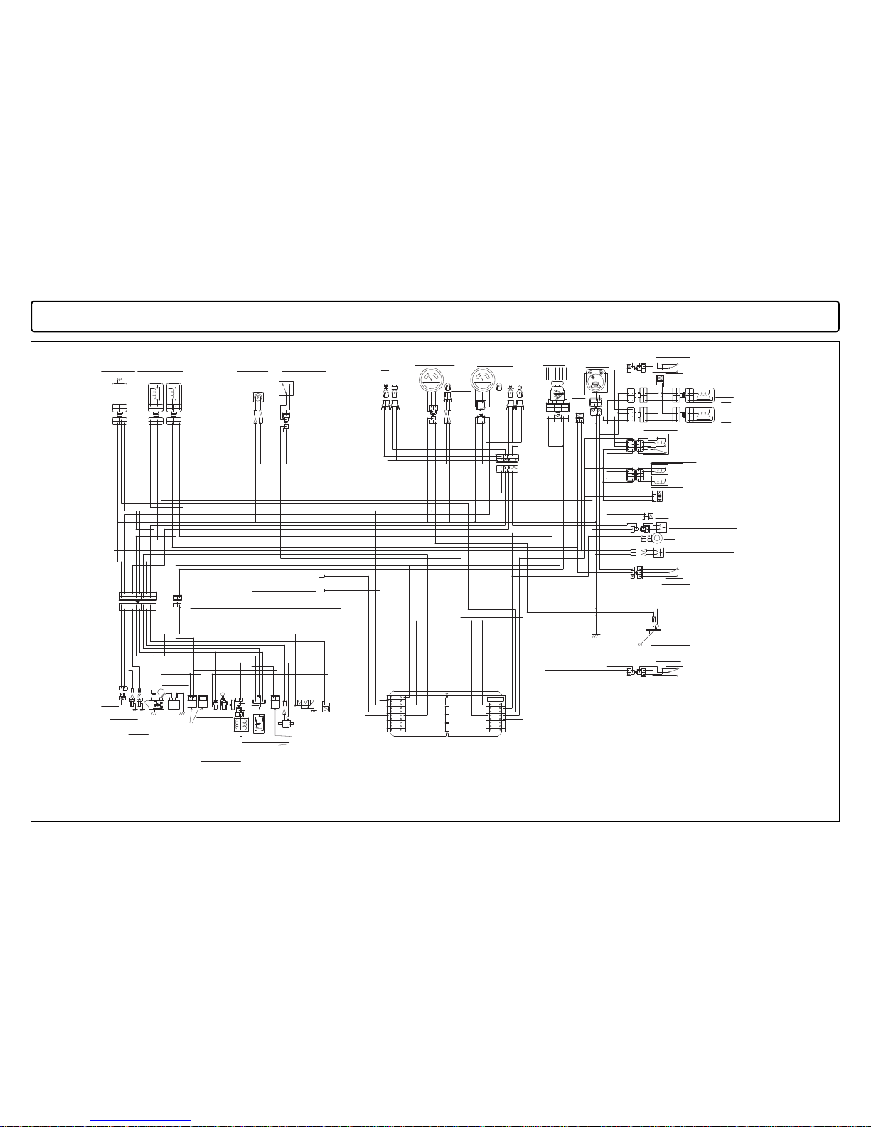
WIRING HARNESS CABLE
85
WIRING HARNESS CABLE
4WD SW
99S
52
30
15B
99Q
52B5652A
57
525152C
63
47E
26
47C
99F
391124
41C
34A
5
23
24A
99J
991051111582
13
6
14
20
18
14
6
32
31
21B
2166A
39 14
25D
40A
40B
40C
59
59
59A
41
60
99V
40
27
27A
28A
25C
99T
28
33
5A
33A
41B
23A
34
31
99H
40
32
99B
99W
61
25
26
24
23
17
18
15A
19
20
13
2
61
4515
10
15D
41B
60A
41C
25E
60
41A
21
14
21A
.51.5
3
3
3.0 WR
3.0 WB
3.0 RB
3.0 B
3.0 W
3.0 WB
0.5 B
2.0 BW
3.0 WR
3.0 R
3.0 R
2.0 BW
0.5 YL
0.5 YB
0.5 WR
0.5 RY
3.0 RB
3.0 W
3.0 R
0.5 L
0.5 LW
0.5 RL
3.0 BR
2.0 B
0.5 WY
0.5 YB
3.0 B
0.5 WR
0.5 LW
3.0 W
2.0 BW
0.5 WR
0.5 RY
3.0 BR
0.5
RL
0.5
P
0.5 B
0.5 LgR
0.5 YL
0.5 LR
0.5 GY
2.0 BW
0.5 LW
0.5 RY
0.5 WR
0.5 RL
0.5 GR
3.0 W
3.0 BR
0.5 YL
17
50
FUEL
30
AC
50
AC50
AC30
空き
17
19
+−
TEMP
+−
FUSE BOX
GND
B
12V
S
2
1
19
30 1719
0
3
50A50A
40A
0.5 R
0.5 YG
0.5 OrW
0.5 OrB
0.5 B
0.5 LR
0.5 YR
0.5 Pu
0.5 W
3.0 B
2.0 Lg
0.5 GY
0.85 RB
0.5 L
0.5 Pu
0.5 YL
0.5 RY
0.5 LW
0.5 YB
0.5 RY
0.5 B
0.5 GR
2.0 BW
0.5 YR
2.0 BW
0.5 RY
0.5 YL
0.5 YB
0.5 WY
0.5 LgR
3.0 B
0.5 RY
0.5 B
0.5 Pu
0.5 YG
0.5 WY
0.5 B
0.5 RY
10A
MINI FUSE
15A
3A
15A
15A
FUSE PULLER
10A
5A
10A
15A
0.5 OrB
0.5 OrW
10A
10A
15A
3A
角穴取付タイプ
0.5 Gr
3.0 BR
2.0 BW
3.0 W
0.5 W
0.5 B
3.0 RW
3.0 BR
0.5 R
0.5 W
0.5 W
0.5 W
0.5 L
0.5 Gr
0.5 B
4WD
0.5 G
0.5 G
0.5 B
0.5 RY
空き
0.5 B
0.5 GB
0.5 GB
0.5 BrR
10A5A
0.5 R
0.5 Gr
0.5 YW
0.5 YW
0.5 YW
CHARGE
OIL PRESSURE
FULL COLLECTOR
2.0 Lg(BATTERY DIRECT POWER(15A,OPTIONAL))
3.0 W(BATTERY DIRECT POWER)
3.0 R W(AC POWER)
3.0 R W(AC POWER)
3.0 R W(AC POWER)
0.5 Gr(AC POWER(10A,PTO CONTROLL PARTS))
1.25 BrR(AC POWER(10A,WORK LAMP))
1770−623−200−0 HARNESS(MAIN)ASSY
1770−623−300−0 HARNESS(ENGINE)ASSY
TIMER
0.5 RL(AC POWER(3A,FUELポンプ))
0.5 RY(AC POWER(10A,METER、MONITOR))
0.5 GY(AC POWER(5A,HORN))
0.5 LgR(AC POWER(10A,ENGINE START PARTS))
1770−623−700−0 HARNESS(MAIN)ASSY
0.85 RB(AC POWER(10A,OPTIONAL))
OIL SW
SLOW BLOW FUSE
Red50A
SLOW BLOW FUSE
Green40A
PTO SW
DIODE
DIODE
HORN
DIODE
38
99105111
15
8
13
2
0.5 P
0.5 LW
0.5 P
38
0.5 WR
71
72
73
74
0.5 WR
99 99a
0.5 YR30.5 GR
32A
31A
0.5 B
0.5 WY
99b
15E
0.5 GB
0.5 B
47D
99X
0.5 B
0.5 GB
47
0.5 GB
DELAY RELAY
BUZZER RELAY
START RELAY
WORK LAMP
WORK LAMP SW
FUEL METER
FUEL METER
LAMP(OPT)
TEMP METER
KEY SW
UP CUT SW
PTO CUT
RELAY
UP CUT
RELAY
PTO RELAY
PTO SOLENOID
BRAKE SW
FUEL SENSOR
TEMP
SENSOR
OVER
HEAT SW
BATTERY
STARTER
MOTOR
ALTERNATOR
SOLENOID RELAY
GLOW PLUG
FUEL PUMP
SEAT SW
(LOCAL ARRANGEMENT)
〇 E: THE PART WHICH IS INCLUDED
IN THE ENGINE.
〇
H
: THE PART WHICH IS INCLUDED
IN THE HARNESS.
HALF PRESSURE
ALL PRESSURE
0.5 OrW
0.5 OrB
0.5 OrB
0.5 Gr
GREEN COUPLER
25A
27
25B
28A
ENGINE STOP
SOLENOID
DIODE
(only
−700−)
FULL COLLECTOR SW
(LOCAL ARRANGEMENT)
OPTION DC12V
(AC:ACCESSORY)
OPTION DC12V
(B:BATTERY DIRECT)
0.5 YW 1
J
0.5 YW 4
0.5 L 6
0.5 R 5
0.5 W2 30.5 WB
0.5 W2B
3A0.5 WB
3B0.5 WB
1000
0.5 W2A
0.5 B
EXCEPT G TYPE

SF310,370
86
21B
2166A
39 14
25D
40A
40B
40C
59
59
59A
41
60
99V
40
27
27
27A
25C
25A
99T
28
25B
33
5A
33A
23A
34
31
99H
40
32
15F
99B
99W
61
25
26
24
23
22
17
18
15A
19
20
13
53C
49
53D
54
53B
53A
50
55
99U
462943
37
3312
61
4515
10
15D
41B
41A
17A
63
41B
28A
28
60A
41C
25E
60
15A
99X
21A
14
21
99S
52
30
15B
99Q
52B5652A
57
525152C6353
58
46C35
171936
45C4322
4744
46B
45B
36A
34
99P
26
46
99D99F
4344
99N
99E4599C
37
36
35
99A
391124
41C
34A
5
23
38
24A
99J
991051111582
13
6
14
45A
47A
46A 99G
20
18
99
30
99105111
15
8
13
2
14
6
38
38
12
33A
63
99L99M
63A
32
31
47
47B
47E
47C
47D
SEAT SW
(LOCAL ARRANGEMENT)
STOP SW
FULL COLLECTOR SW
(LOCAL ARRANGEMENT)
.51.5
3
3
3.0 WR
3.0 WB
0.5 WR
3.0 RB
3.0 B
3.0 W
3.0 WB
0.5 B
3.0 WR
3.0 R
3.0 R
2.0 BW
0.5 YL
0.5 YB
0.5 WR
0.5 RY
3.0 RB
3.0 W
3.0 R
0.5 L
HORN
DIODE
0.5 LW
0.5 RL
3.0 BR
2.0 B
0.5 GrR
0.5 LB
0.5 LB
1.25 G
1 OrL
0.5 WY
0.5 YB
3.0 B
0.5 Br
0.5 WR
0.5 LW
3.0 W
2.0 BW
0.5 RY
0.5 LR
0.5 B
3.0 BR
0.5 RL
0.5 P
0.5 B
0.5 LgR
0.5 YL
0.5 LR
0.5 GY
2.0 BW
0.5 LW
0.5 RY
0.5 RL
0.5 GR
3.0 W
3.0
BR
0.5
YL
L
R
17
50
FUEL
30
AC
50
AC50
AC30
空き
17
19
+−
Hi BEAM
P
PTO SW
TEMP
OIL SW
+−
FUSE BOX
GND
B
12V
S
2
1
19
30 1719
0
3
50A50A
40A
0.5 WY
DIODE
1
.
25
B
1
.
25
Y
0.5 LB
0.5 B
0.5 B
1
.
25
G
0.5
PL
21WX221WX2
GND
0.5 OrB
0.5 R
0.5 YG
0.5 OrW
0.5 OrB
0.5 Or W
0.5 Gr
0.5 OrB
0.5 GrR
0.5 B
0.5 B
0.5 LR
0.5 GB
1.25
.25
PB
0.5 YR
0.5 Pu
0.5 W
3.0 B
2.0 Lg
0.5 GY
0.85 RB
1.25 Br
Hi
0.5 L
DIODE
0.5 Pu
0.5 GrR
0.5 B
0.5 GB
Lo
0.5 LB
0.5 YL
1.25 RG
0.5 RY
1.25 R
1.25 Y
0.5 GrR
0.5 LW
0.5 B
0.5 LB
0.5 YB
0.5 RY
0.5 B
0.5 GR
0.5 GB
1.25 G
29
0.5 BY
2.0 BW
0.5 YR
2.0 BW
0.5 RY
0.5 GB
0.5 YL
0.5 YB
0.5 WY
0.5 LgR
3.0 B
0.5 RY
0.5 B
0.5 Pu
0.5 YG
0.5 WY
0.5 B
0.5 RY
10A
MINI FUSE
15A
3A
15A
15A
FUSE PULLER
10A
5A
10A
10A 15A
0.5 OrB
0.5 Or W
10A
10A
15A
3A
角穴取付タイプ
0.5 Gr
3.0 BR
2.0 BW
3.0 W
0.5 GrR
0.5 B
0.5 W
0.5 B
3.0 RW
3.0 BR
0.5 YW
0.5 B
0.5 B
0.5 Br
0.5 B
0.5 PL
0.5 RY
0.5 R
0.5 W
0.5 W
0.5 W
0.5 Gr
0.5 B
4WD
0.5 G
0.5 G
0.5 B
4WD SW
0.5 RY
空き
0.5 B
0.5 LY
0.5 GB
0.5 BrR
5A
0.5 P0.5 P
0.5 P
0.5 WR0.5 WR
0.5 W(PUMP)
1.25 B
1.25 OrL
21WX2
40/45WX2
21W21W
0.5 R
0.5 GR
0.5 B
0.5 RB
0.5 B
0.5 RB
0.5 R
C3C2
31
C
49
49a
0.5 Gr
0.5 L
0.5 YW
0.5 YW
0.5 YW
0.5 B
0.5 GB 0.5 GB
0.5 B
DELAY RELAY
START RELAY
FLASHER RELAY
TRAILER
FLASHER
POWER
STOP(L)FLASHER(L)
POTITION LAMPS
WORK LAMP(FRONT)
FLASHER(R)
STOP(R)
SMALL LAMP SW
CHARGE
TRAILER
FLASHER(L)
FUEL METER
FUEL METER
LAMP(OPT)
PARKING BRAKE
OIL PRESSURE
FLASHR(R)
FULL COLLECTOR
KEY SW
TEMP METER
BUZZER
RELAY
HEAD LAMPS
COMBI SW
HAZZARD SW
UP CUT SW
UP CUT
RELAY
PTO CUT
RELAY
PTO RELAY
TIMER
PTO SOLENOID
HALF PRESSURE
ALL PRESSURE
FUEL SENSOR
0.5 RL(AC POWER(3A,FUEL PUMP))
1.25 RG(AC POWER(15A,FLASHER))
0.5 RY(AC POWER(10A,METER,MONITOR))
2.0 Lg (BATTERY DIRECT POWER(15A,OPTIONAL))
1.25 R(BATTERY DIRECT POWER(15A,HAZZARD))
3.0 W(BATTERY DIRECT POWER)
3.0 R W(AC POWER)
3.0 R W(AC POWER)
3.0 R W(AC POWER)
1.25 PB(AC POWER(15A,LAMP))
0.5 Gr(AC POWER(10A,PTO CONTROLL PARTS))
0.5 GY(AC POWER(5A,HORN))
0.5 LgR (AC POWER(10A,ENGINE START PARTS))
TRAILER
1770−623−300−0 HARNESS(ENGINE)ASSY
TEMP
SENSOR
STARTER
MOTOR
SOLENOID RELAY
FUEL PUMP
GLOW PLUG
BATTERY
OVER HEAT
SW
SLOW BLOW FUSE
Red50A
SLOW BLOW FUSE
Green40A
ALTERNATOR
1770−623−500−0 HARNESS(MAIN/G) ASSY
ENGINE STOP
SOLENOID
0.85 RB(AC POWER(10A,OPTIONAL))
OPTION DC12V
(B:BATTERY DIRECT)
OPTION DC12V
(AC:ACCESSORY)
1.25 BrR(AC POWER(10A,WORK and POSITION LAMPS))
99a99
0.5 B
0.5 WY
99b
15E
〇 E: THE PART WHICH IS INCLUDED
IN THE ENGINE.
〇
H
: THE PART WHICH IS INCLUDED
IN THE HARNESS.
BRAKE SW
PARKING
BRAKE SW
GREEN COUPLER
(LOCAL ARRANGEMENT)
7
14A
8
8A
74
0.5 YW 1
J
0.5 YW 4
0.5 L 6
0.5 R 5
0.5 W2 30.5 WB
0.5 W2B
3A0.5 WB
3B0.5 WB
1000
0.5 W2A
0.5 B
G TYPE

WIRING HARNESS CABLE
87
Red50A
Green40A
0.5 YW 1
J
0.5 YW 4
0.5 L 6
0.5 R 5
0.5 W2 30.5 WB
0.5 W2B
3A0.5 WB
3B0.5 WB
1000
0.5 W2A
0.5 B
F2 TYPE


SF310
SF370
O
verseas Business Divisio
n
5
-3-14, Nishi-Nippori, Arakawa-ku,
Tok
y
o 116-8541, Japa
n
Phone: (03) 5604-765
8
Fax: (03) 5604-7703
Parts Code: 1770-912-101-4I-EN
Publishing date: 10th August 2017
Printed in Japan
 Loading...