

Page 1
user manual
Last changed on: 19.01.2018
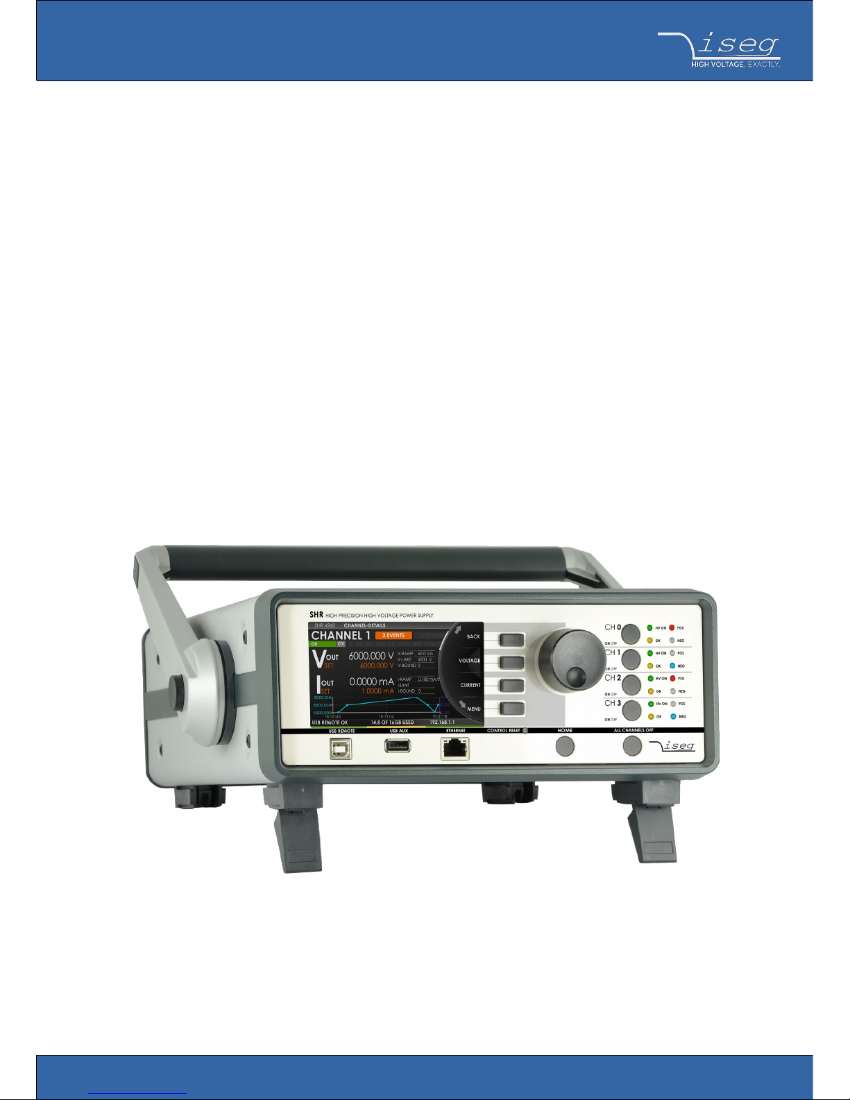
SHR series
Switchable high end high precision AC/DC desktop HV supply
• 2 / 4 channel, 2 kV / 6kV versions
• electronically switchable polarity
• versatile 6kV-channel with switchable HV-generation modes: up to 6kV/2mA, 4kV/3mA or 2kV/4mA
• high precision / ultra low ripple and noise
• Ethernet / USB interfaces, integrated iCS2 on ARM Linux server hardware
• 4.3” TFT capacitive touch display
• comprehensive features including logging, diagrammatic display and script control
- preliminary -
www.iseg-hv.com
Page 2
Document history
Version Date Major changes
1.0 19.01.2018 Initial version
Disclaimer / Copyright
Copyright © 2018 by iseg Spezialelektronik GmbH / Germany. All Rights Reserved.
This document is under copyright of iseg Spezialelektronik GmbH, Germany. It is forbidden to copy, extract parts, duplicate for
any kind of publication without a written permission of iseg Spezialelektronik GmbH. This information has been prepared for
assisting operation and maintenance personnel to enable efficient use.
The information in this manual is subject to change without notice. We take no responsibility for any mistake in the
document. We reserve the right to make changes in the product design without reservation and without notification to
the users. We decline all responsibility for damages and injuries caused by an improper use of the device.
Important security information
It is strongly recommended to read the operator´s manual before operation. To avoid injury of users it is not allowed to
open the unit. There are no parts which can be maintained by users inside of the unit. Opening the unit will void the
warranty.
We decline all responsibility for damages and injuries caused by an improper use of the module. It is strongly
recommended to read the operators manual before operation.
WARNING!
WARNING!
The non-observance of the advices marked as “Warning!” could lead to possible injury or death.
ATTENTION!
ATTENTION!
Advices marked as “Attention!” describe actions to avoid possible damages to property.
INFORMATION
INFORMATION
Advices marked as “Information” give important information.
SHR – Desktop High Voltage Power Supply | Last changed on: 19.01.2018 | www.iseg-hv.com 2/11
Page 3

Safety notes
CAUTION!
CAUTION
To avoid injury of users it is not allowed to open the unit. Before any operations on the HV output or the
application, the unit has to be switched off and discharge of residual voltage has to be finished. Depending on
application residiual voltages can be present for long time periods. These residiual voltages can lead to severe
injuries.
SHR – Desktop High Voltage Power Supply | Last changed on: 19.01.2018 | www.iseg-hv.com 3/11
Page 4

Table of Contents
- preliminary -.................................................................................................................................................................................................1
Document history............................................................................................................................................................................. 2
Disclaimer / Copyright......................................................................................................................................................................2
Important security information...................................................................................................................................................... 2
Safety notes.......................................................................................................................................................................................3
1 General description....................................................................................................................................................................................5
2 Technical Data............................................................................................................................................................................................. 5
3 Handling.......................................................................................................................................................................................................7
4 Options.........................................................................................................................................................................................................7
4.1 VCT – voltage correction by temperature...............................................................................................................................7
4.1.1 Technical data........................................................................................................................................................................7
4.1.2 Operation...............................................................................................................................................................................7
4.2 Single Channel Inhibit...............................................................................................................................................................8
4.3 IHD - Detector INHIBIT.............................................................................................................................................................. 9
4.4 L – Lower output current (HP only)......................................................................................................................................... 9
4.5 T10 – Lower temperature coefficient (HP only)..................................................................................................................... 9
5 Dimensional drawings............................................................................................................................................................................... 9
6 Connectors and PIN assignments..........................................................................................................................................................10
7 Order guides............................................................................................................................................................................................. 10
8 Appendix....................................................................................................................................................................................................11
9 Warranty & Service...................................................................................................................................................................................11
10 Manufacturer´s contact........................................................................................................................................................................ 11
SHR – Desktop High Voltage Power Supply | Last changed on: 19.01.2018 | www.iseg-hv.com 4/11
Page 5

1 General description
WARNING!
WARNING!
The devices induce output voltages and currents which conformable to EN61010-1 are not
dangerous to life. But it is possible that they effect health damages to sensitive persons.
The iseg SHR modules are standalone High Precision HV laboratory SMU – Source Measuring Unit – equipped with the
finest iseg HV generation technology and iCS control system.
The SHR provides up to 4 channels, each with an independent voltage and current control and electronically reversible
polarity. The 6kV channel provides a maximum versatility: with three electronically switchable HV-output modes it can
supply 4mA up to voltages of 2kV, 3mA up to 4kV and 2mA up to 6kV. Alternatively the SHR can be equipped with cost
efficient 2kV/6mA channels.
A high quality 4.3” TFT display shows detailed information and can be controlled by capacitive touch. All comprehensive
features like logging, graphical display and customer specific plugins are also available by the precise jog-wheel and
buttons.
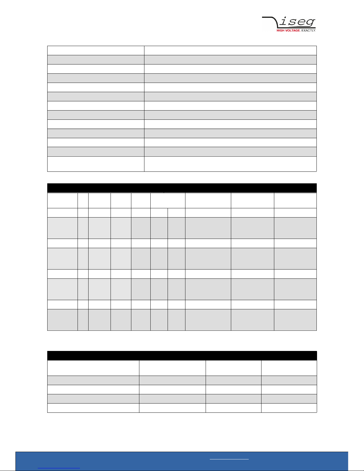
2 Technical Data
SPECIFICATIONS SHR Standard SHR High Precision
Polarity Electronically switchable
Ripple and noise (f > 10 Hz) < 10 mV
p-p
< 2-3 mV
p-p
Ripple and noise (f > 1 kHz) < 3 mV
p-p
< 2 mV
p-p
Ripple and noise (10 Hz – 0.1Hz) < 5-10 mV
p-p
Stability [ΔVout / ΔVin] 2 • 10-4 • V
mode
11 • 10
• 10
-4
-4
•
•
V
V
mode
mode
Stability - [ΔVout / ΔRload] 2 • 10-4 • V
mode
11 • 10
• 10
-4
-4
•
•
V
V
mode
mode
Temperature coefficient 50 ppm/K 30 ppm/K | 10 ppm/K (option TC)
Resolution voltage setting 2 • 10-6 • V
nom
Resolution current setting 2 • 10-6 • I
nom
Resolution voltage measurement 2 • 10-6 • V
nom
1 • 10-6 • V
nom
Resolution current measurement - full range 2 • 10-6 • I
nom
1 • 10 -6 • I
nom
Resolution current measurement - 2nd range n/a 50 pA [I
out
< 20 μA]
Accuracy voltage measurement ± (0.01 % • V
out
+0.02 % • V
nom
) ± (0.01 % • V
out
+0.01 % • V
nom
)
Accuracy current measurement - full range ± (0.01 % • I
out
+0.02 % • I
nom
) ± (0.01 % • I
out
+0.01 % • I
nom
)
Accuracy current measurement - 2nd range n/a ± (0.01 % • I
out
+ 4 nA)
Measurement accuracy - The measurement accuracy is guaranteed in the range 1% •• V
mode
< V
out
< V
mode
and for 1 year
Sample rates (SPS) 5, 10, 25, 50, 60, 100, 500
Digital filter averages 1, 16, 64, 256, 512, 1024
Hardware limits Potentiometer per module [V
max
/ I
max
]; relative to V
nom
/ I
nom
Voltage ramp 1*10-6 • V
mode
/s up to 0.2 • V
mode
/ s
SHR – Desktop High Voltage Power Supply | Last changed on: 19.01.2018 | www.iseg-hv.com 5/11
Page 6
Rated AC mains input 100 – 240 VAC / 1-0.5 A max / 50-60 Hz
Fuse T 1.6A L 250V / microfuse 5mm x 20mm, 250V / 1.6AT
AC power connector socket according IEC 60320 C13 (125V/10A or 250V/16A)
HV connector SHV
Safety Loop connector Lemo 2pole: FFA.0S.302.CLAC
Safety Loop socket Lemo 2pole: ERA.0S.302.CLL
Interfaces Ethernet, USB(A) 2.0 (Host: Wifi, Logging, Webcam), USB(B) (remote control)
Protection INHIBIT, Safety loop, short circuit, overload, hardware V/I limits
Case desktop case
Dimensions (L/W/H) 331/257/103 mm
Operating temperature 0 – 40 °C
Storage temperature -20 - 60 °C
Further environmental conditions equipment is for use in closed environment only, relative humidity 20% to 90%
(no condensation), maximum Pollution degree level 2
Table 1: Technical data: Specifications
CONFIGURATIONS SHR
Type Ch Precision V
nom
I
nom
Ripple (mV
p-p
)
>1kHz|10Hz-1kHz
HV output mode
(V
mode
/ I
mode
)
Item Code Options
SHR 20 20 2 Standard 2000 V 6 mA 3 10 2 kV / 6 mA SR020020r605 VCT,IHB,IHD
SHR 20 60 2 Standard 6000 V 4 mA 3 10 6 kV / 2mA
4kV / 3mA
2kV / 4mA
SR020060r405 VCT,IHB,IHD
SHR 40 20 4 Standard 2000 V 6 mA 3 10 2 kV / 6 mA SR040020r605 VCT,IHB,IHD
SHR 40 60 4 Standard 6000 V 4 mA 3 10 6 kV / 2mA
4kV / 3mA
2kV / 4mA
SR040060r405 VCT,IHB,IHD
SHR 22 20 2 High 2000 V 6 mA 2 2 2 kV / 6 mA SR022020r605 VCT,IHB,IHD,TC,L
SHR 22 60 2 High 6000 V 4 mA 2 3 6 kV / 2mA
4kV / 3mA
2kV / 4mA
SR022060r405 VCT,IHB,IHD,TC,L
SHR 42 20 4 High 2000 V 6 mA 2 2 2 kV / 6 mA SR042020r605 VCT,IHB,IHD,TC,L
SHR 42 60 4 High 6000 V 4 mA 2 3 6 kV / 2mA
4kV / 3mA
2kV / 4mA
SR042060r405 VCT,IHB,IHD,TC,L
Table 2: Technical data: Configurations
OPTIONS / ORDER INFO INFO EXAMPLE ITEM CODE HEX CODE
SINGLE CHANNEL INHIBIT – BNC
connectors
IHB SHR 4260 IHB 400
DETECTOR INHIBIT (ORTEC/CANBERRA) IHD SHR 4260 IHD 800
VOLTAGE CORRECTION by TEMPERATURE VCT SHR 4260 VCT 008
LOWER TEMPERATURE COEFFICIENT TC SHR 4260 T10 004
LOWER OUTPUT CURRENT L (I
nom
= 100 μA) SHR 4260 L -
Table 3: Technical data: Options and order information
SHR – Desktop High Voltage Power Supply | Last changed on: 19.01.2018 | www.iseg-hv.com 6/11
Page 7

3 Handling
- to be continued -
CAUTION!
CAUTION!
The device is not designed to operate as a current sink.
Never apply external voltages of opposite polarity to the selected one or with values greater than the maximum
value of the selected output mode. This can damage the module.
4 Options
4.1 VCT – voltage correction by temperature
This option allows a temperature dependent correction of the output voltage. The temperatures are measured with a
distinct sensor for each channel. The temperature sensors are connected via BNC connectors on the backplane of the
module. An user-adjustable VCT-coefficient allows to specify a linear relationship between the measured temperature and
the output voltage. As an option one sensor per module can be orded.
4.1.1 Technical data
Sensor type EPCOS B57867S0502F140
Temperature range -40 … 80°C
Accuracy of temperature measurement ±0.5 K (0 … 60°C)
Resolution of temperature measurement 1 mK (0 … 60°C)
Temperature update rate 15 updates/min
Table 5: Technical data VCT sensor
4.1.2 Operation
The connector of the temperature sensor must be plugged in the slot of the corresponding channel on the VCT-connector
at the rear panel of the HV-module.
A programmable VCT-coefficient for each channel defines the rate and the direction of the voltage correction. The
temperatures, measured at the sensors can be read out from the module.
At the time a HV-channel is switched on or the output voltage is set by the user, the module registers the temperature of
the corresponding sensor and the set voltage as reference values.
If the temperature at the sensor changes, the output voltage is automatically adjusted according to the formula:
V = V
ref
+ a*(T-T
ref
) (a…VCT-coefficient)
Example: A channel is set to 60V. At the time it is switched on a temperature of 25°C is measured. The VCT-coefficient is
set to +1V/K. If the temperature now increases to 26°C the output voltage will increase to 61V. (For channels with a
negative output voltage the voltage changes from –60V to –61V).
A VCT-coefficient of -1V/K would decrease the voltage to 59V.
SHR – Desktop High Voltage Power Supply | Last changed on: 19.01.2018 | www.iseg-hv.com 7/11
Page 8
Notes:
• During operation the values for Vset are adjusted. If a channel is switched off the adjusted set value will be kept, not the
original value set by the user.
• If the VCT-coefficient if modified during operation, Vref and Tref are reset to the present values to prevent a sudden
voltage change.
• If the temperature sensor is dis- and reconnected during operation, Vref and Tref are reset to the present values to
prevent a sudden voltage change.
• The temperature dependent voltage correction can be deactivated by setting the VCT-coefficient to 0 or by
disconnecting the temperature sensor. If this is done during operation, the channel will keep the actual voltage set.
• If the temperature sensor is disconnected a temperature of -273.15°C is shown for that channel.
• The VCT data points are described in the manual "iseg Hardware Abstraction Layer" (see appendix).
4.2 Single Channel Inhibit
INFORMATION
INFORMATION
INHIBIT is an external signal, that switches off the high voltage for the device or a specific channel
If none of the options IHB, IHD or VCT is ordered, modules are equipped with an INHIBIT for each channel via a Sub-D
connector on the backplane of the module. Channel 0 to 3 corresponds to Pin 1 to 4 at the Sub-D connector, Pins 5-9 are
connected to GND.
With option IHB the module is equipped with BNC connectors for the INHIBIT of each channel instead.
The INHIBIT signal are TTL-level, the signal logic and default states can be configured. The following settings are possible:
Case 1 – IU
INHIBIT signal logic: LOW-active (LOW HV-generation stopped)→
default state: HIGH (internal pull-up resistor applied)
open INHIBIT signal input: HV enabled
Case 2 – ID
INHIBIT signal logic: LOW-active (LOW HV-generation stopped)→
default state: LOW (internal pull-down resistor applied)
open INHIBIT signal input: HV disabled
Case 3 – NIU
INHIBIT signal logic: HIGH-active (HIGH HV-generation stopped)→
default state: HIGH (internal pull-up resistor applied)
open INHIBIT signal input: HV disabled
Case 4 – NID
INHIBIT signal logic: HIGH-active (HIGH HV-generation stopped)→
default state: LOW (internal pull-down resistor applied)
open INHIBIT signal input: HV enabled
SHR – Desktop High Voltage Power Supply | Last changed on: 19.01.2018 | www.iseg-hv.com 8/11
Page 9

The INHIBIT signal must be applied for at least 100 ms to guarantee a detection. When the INHIBIT is no longer active, the
INHIBIT flag must be reset before the voltage can be switched ON again.
4.3 IHD - Detector INHIBIT
The option IHD is a special version of a single channel INHIBIT to be connected to the HV INHIBIT outputs of
detectors/preamplifiers from Ortec and Canberra. In order to enable the HV generation either a positive voltage signal
(Canberra) or a negative signal (ORTEC) must be applied. The INHIBIT signals are connected via BNC connector (one for
each channel) located on the backplane of the module.
4.4 L – Lower output current (HP only)
The output current is limited to a lower value, e.g. 100 µA.
4.5 T10 – Lower temperature coefficient (HP only)
Improved temperature coefficient of 10ppm/K
5 Dimensional drawings
- to be continued -
Figure 1: Dimensional drawings
SHR – Desktop High Voltage Power Supply | Last changed on: 19.01.2018 | www.iseg-hv.com 9/11
Page 10

6 Connectors and PIN assignments
HV CONNECTOR ASSIGNMENTS
Name SHV
Figure
INHIBIT
Name INHIBIT connector- DSUB9 INHIBIT connector- DSUB9
Figure
PIN INHIBIT 1
1 CHANNEL 0
2 CHANNEL 1
3 CHANNEL 2
4 CHANNEL 3
5 GND
6 GND
7 GND
8 GND
9 GND
Table 7: Connector and pin assignments
CONNECTORS PART NUMBERS (manufacturer code / iseg accessory parts item code)
POWER SUPPLY SIDE CABLE SIDE
SHV (ROSENBERGER)
Socket Connector 57K101-006N3 / Z590162
Table 8: Connectors part number information
7 Order guides
CABLE ORDER GUIDE
POWER SUPPLY SIDE
CONNECTOR
CABLE
CODE
CABLE DESCRIPTION LOAD SIDE
CONNECTOR
ORDER CODE
LLL = length in m
(*
SHV 04 HV cable shielded 30kV (HTV-30S-22-2) open SHV_1C04-LLL
*)
Length building examples: 10cm => 0.1, 2.5m => 2.5, 12m => 012 , 999m => 999
Table 9: Guideline for cable ordering
CONFIGURATION ORDER GUIDE (item code parts)
SR 04 0 020 r 605 000 02 00
High
Voltage,
Distinct
Source
Numbers of
channels
Class V
nom
Polarity I
nom
(nA) Option (hex) HV-Connector Customized
Version
02 = 2ch
04 = 4ch
0 = Standard
4 = High
Precision
three significante
digits *100V
For Examle:
020 = 2000V
r = reversible two significante
digits + number
of zeros
For Examle:
605 = 6mA
Sum of the hex
codes (s. table
3)
For Example:
IU + TC = 804
02 = SHV 00 = none
Table 10: Item code parts for different configurations
SHR – Desktop High Voltage Power Supply | Last changed on: 19.01.2018 | www.iseg-hv.com 10/11
Page 11

8 Appendix
For more information please use the following download links:
This document
http://download.iseg-hv.com/AC_DC/SHR/iseg_manual_SHR_en_1.0.pdf
SHR SCPI Programmers-Guide
http://download.iseg-hv.com/AC_DC/SHR/iseg_SHR_SCPI_ProgrammersGuide_en.pdf
9 Warranty & Service
This device is made with high care and quality assurance methods. The factory warranty is up to 36 months, starting from
date of issue (invoice). Within this period a 5 years warranty extension can be ordered at additional charge. Please contact
iseg sales department.
CAUTION!
Repair and maintenance may only be performed by trained and authorized personnel.
For repair please follow the RMA instructions on our website: www.iseg-hv.com/en/support/rma
10 Manufacturer´s contact
iseg Spezialelektronik GmbH
Bautzner Landstr. 23
01454 Radeberg / OT Rossendorf
GERMANY
FON: +49 351 26996-0 | FAX: +49 351 26996-21
www.iseg-hv.com | info@iseg-hv.de |sales@iseg-hv.de
SHR – Desktop High Voltage Power Supply | Last changed on: 19.01.2018 | www.iseg-hv.com 11/11
 Loading...