

Page 1
iseg Spezialelektronik GmbH Email: sales@iseg-hv.de Phone ++ 49 (0)351 / 26 996 – 0
Bautzner Landstr. 23 http://www .iseg-hv.com Fax ++ 49 (0)351 / 26 996 – 21
D - 01454 Radeberg / Rossendorf Germany
Operator’s Manual
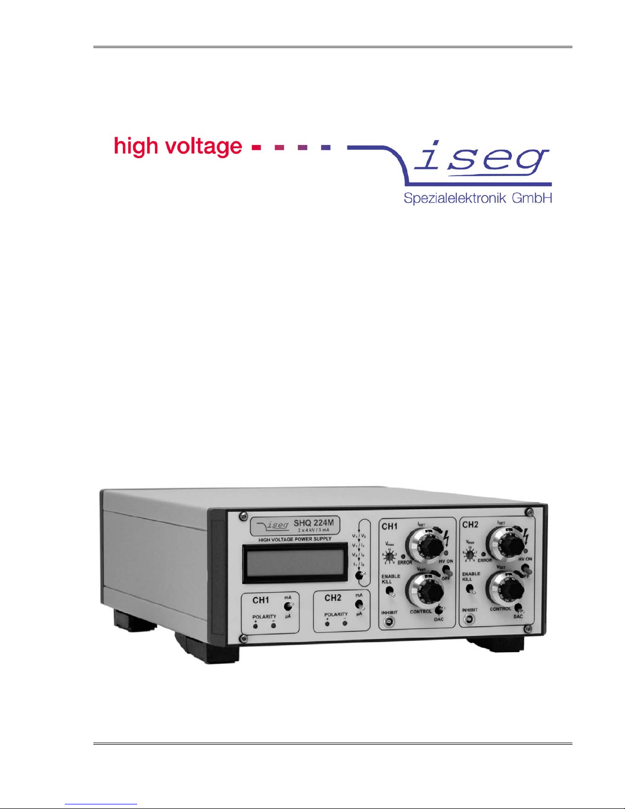
High Voltage Power Supply
SHQ HIGH PRECISION series
Page 2
Spezialelektronik GmbH
iseg Spezialelektronik GmbH Email: sales@iseg-hv.de Phone ++ 49 (0)351 / 26 996 – 0
Bautzner Landstr. 23 http://www.iseg-hv.com Fax ++ 49 (0)351 / 26 996 – 21
2 D - 01454 Radeberg / Rossendorf Germany
Basic Information
It is strongly recommended to read the operator’s manual before operation.
To avoid injury of users it is not allowed to open the unit. There are no parts which can be maintained by users inside of the
unit. Opening the unit will void the warranty.
The mains connector is equipped with basic insulation and a protective earth conductor. The unit may only be operated with
protective earth conductor connected.
We decline all responsibility for damages and injuries caused by an improper use of the module. It is strongly recommended
to read the operators manual before operation.
The information in this manual is subject to change without notice. We take no responsibility for any error in the document.
We reserve the right to make changes in the product design without reservation and without notification to the users.
Violation of guidelines marked with „Warnin g “ can lead to death or severe injury
Violation of guidelines marked with „Attention!“ can lead to damages of the unit or the application
Text marked with „Note!“ point at specialties or options.
Revision of document:
2014-02-13-17-34
Page 3

Spezialelektronik GmbH
iseg Spezialelektronik GmbH Email: sales@iseg-hv.de Phone ++ 49 (0)351 / 26 996 – 0
Bautzner Landstr 23 http://www.iseg-hv.com Fax ++ 49 (0)351 / 26 996 – 21
D - 01454 Radeberg / Rossendorf Germany 3
Content
1 Safety notes..................................................................................................................................................................... 4
2 General information ......................................................................................................................................................... 5
2.1 Short description..................................................................................................................................................... 5
2.2 Technical Data and auxiliary information................................................................................................................. 6
2.2.1 Device class........................................................................................................................................................ 6
3 Functional principle.......................................................................................................................................................... 7
3.1 High voltage supply.................................................................................................................................................7
3.2 Digital control unit.................................................................................................................................................... 7
3.3 Filter........................................................................................................................................................................ 7
3.4 Floating HV-outputs ................................................................................................................................................ 8
4 Operation......................................................................................................................................................................... 9
4.1 Front panel.............................................................................................................................................................. 9
4.2 Power Up and operational conditions.................................................................................................................... 10
4.2.1 Manual control (“CONTROL” in upper position) ................................................................................................ 10
4.2.2 Remote control (“CONTROL” in lower position)................................................................................................ 11
4.2.3 Transition manual control Ù remote control..................................................................................................... 12
4.3 Current measurement ranges .............................................................................................................................. 12
4.3.1 Current measurement ranges and current trip.................................................................................................. 12
4.4 Safety functions.....................................................................................................................................................12
4.5 Operation check.................................................................................................................................................... 13
5 RS232 interface............................................................................................................................................................. 14
5.1 Specification RS232 interface...............................................................................................................................14
5.1.1 Syntax............................................................................................................................................................... 15
5.1.2 Command set ................................................................................................................................................... 15
Pictures
Picture 1: Scheme of potentials................................................................................................................................................ 8
Picture 2: Front panel ............................................................................................................................................................... 9
Tables
Table 1: Technical Data, Device class.................................................................................................................................... 6
Table 2: Overview KILL function............................................................................................................................................ 13
Table 3: Signal pin assignment.............................................................................................................................................. 14
Table 4: Command set ........................................................................................................................................................... 15
Page 4

Spezialelektronik GmbH
iseg Spezialelektronik GmbH Email: sales@iseg-hv.de Phone ++ 49 (0)351 / 26 996 – 0
Bautzner Landstr. 23 http://www.iseg-hv.com Fax ++ 49 (0)351 / 26 996 – 21
4 D - 01454 Radeberg / Rossendorf Germany
1 Safety notes
To avoid injury of users it is not allowed to open the unit. Before any operations on the HV output
or the application, the unit has to be switched off and discharge of residual voltage has to be
finished. Depending on application residiual voltages can be present for long time periods. These
residiual voltages can lead to severe injuries.
Only accessories which meet the manufacturer’s specifications shall be used. If the equipment is used in a manner not
specified by this manual, the protection provided by the equipment may be impaired. We decline all responsibility for
damages and injuries caused by an improper use of the module.
Page 5

Spezialelektronik GmbH
iseg Spezialelektronik GmbH Email: sales@iseg-hv.de Phone ++ 49 (0)351 / 26 996 – 0
Bautzner Landstr 23 http://www.iseg-hv.com Fax ++ 49 (0)351 / 26 996 – 21
D - 01454 Radeberg / Rossendorf Germany 5
2 General information
2.1 Short description
The modules of the series SHQ are desk top high voltage power supplies which offer output voltages up to 6 kV for the use
in industry and research.
Main Characteristics:
• High voltage power supplies with front-panel operation and remote control via serial interface
• Output voltages with very low ripple and noise
• Compact housing with one or two independent high voltage sources
• Polarity is manually switchable with switches on the rear side of the housing
• Simultaneous display of current and voltage in a High Resolution format on the 2-line LCD
• Output short circuit and overload protection
Page 6
Spezialelektronik GmbH
iseg Spezialelektronik GmbH Email: sales@iseg-hv.de Phone ++ 49 (0)351 / 26 996 – 0
Bautzner Landstr. 23 http://www.iseg-hv.com Fax ++ 49 (0)351 / 26 996 – 21
6 D - 01454 Radeberg / Rossendorf Germany
2.2 Technical Data and auxiliary information
2.2.1 Device class
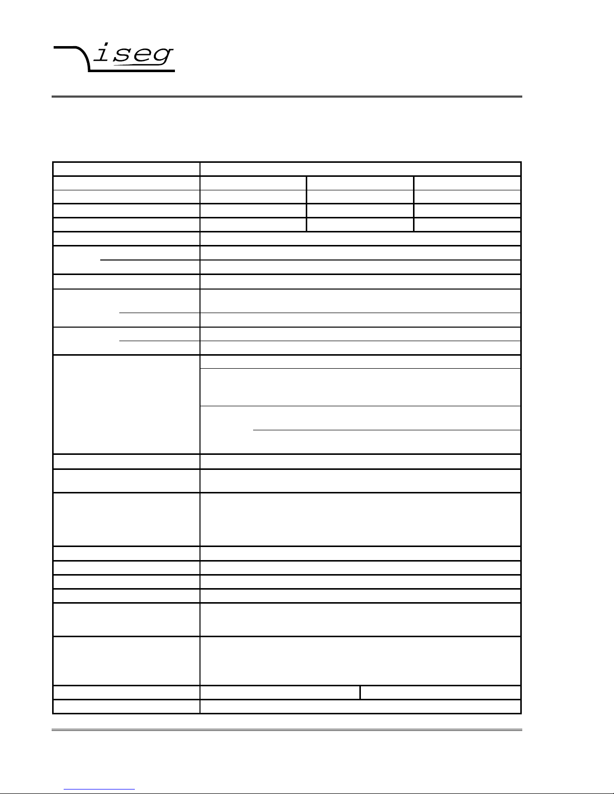
Table 1: Technical Data, Device class
TECHNICAL DATA HIGH PRECISION
Single channel HV Power Supply SHQ 122 SHQ 124 SHQ 126
Dual channel HV Power Supply SHQ 222 SHQ 224 SHQ 226
Output voltage V
nom
2 kV 4 kV 6 kV
Output current I
nom
6 mA 3 mA 1 mA
Ripple and noise typ.: < 2 mV
P-P
max.: 5 mV
P-P
Stability:
∆ V
O
/∆ V
INPUT
< 3 ∗ 10-5 (after a warm-up period of 30 min)
∆V
O
(no load/ load) < 5 ∗ 10-5 (after a warm-up period of 30 min)
Temperature coefficient
< 3 ∗ 10
-5
/
K
Voltage resolution ADC: 100 mV / 6-digit LCD display
(Option VHR: 10 mV for SHQ x22 and x24 only)
measurement accuracy:
± (0,05% V
O
+ 0,02% V
nom
) for one year
Voltage Manual / DAC: 10-turn potentiometer / digital via serial interface
Settings resolution DAC:
100 mV / Option VHR: SHQ x22M with 30 mV; SHQ x24M with 60 mV
Current 2 ranges / 6-digit LCD display
measurement resolution ADC: Range mA:
I
nom
≥ IO ≥ 100 µA, Resolution: 100 nA
Option 0n1: I
nom
≥ IO ≥ 10 µA, Resolution: 100 nA
Accuracy: ± (0,1% I
O
+ 0,02% I
nom
)
Range µA: 100 µA > IO > 20 nA, Resolution: 1 nA
Accuracy: ± (0,1% I
O
+ 20 nA)
Option 0n1: 10 µA > I
O
> 2 nA, Resolution: 100 pA
Accuracy: ± (0,1% I
O
+ 2 nA)
Value scope
data are guaranteed in the range of (1% ∗ V
nom
) < VO < V
nom
for one year
Rate of change of
output voltage
fixed: 500 V/s (at HV-ON/OFF)
variable: 2 ... 255V/s (at remote control)
Protection hardware voltage limit (V
max
rotary switch in 10%-steps)
hardware current limit (I
max
rotary switch in 10%-steps,
Option IWP: setting with 10-turn potentiometer I
SET
)
INHIBIT (external signal, TTL, LOW = active)
programmable current trip (serial interface)
Interface
RS 232-Interface (Option CAN: CAN-Interface ⇒ SHQ x4x)
Line voltage AC (V
INPUT
) 100 VAC .-. 240 VAC / 0,7 – 0,4 A max / 50 – 60 Hz
Fuse T 1A L 250V / microfuse 5mm x 20mm, 250V / 1AT
Mains connection matching used socket according IEC 60320 C13 (125V/10A or 250V/16A)
Connectors HV output: V
O nom
rsp. Typ AMP/Tyco SHV-Connector (225059-3)
INHIBIT: V
O max
5V 1-pin Lemo-hub (ERN.00.250.CTL)
RS 232 : V
O max
+/-20V 9-pin female Sub-D connector
Accessories
see Appendix B
HV output: Rosenberger SHV coupler 57K101-006N3 assembled on HV cable
INHIBIT: LEMO FFA.00.250.CTA, standard cable 5V
RS 232: custom comercially available RS232 cable, uncrossed, female to
male
Temperature ranges Operating: 0 ... +40 °C Storage: -20 ... +60 °C
Desk case Size (W/H/D) : (236/100/320) mm
Page 7

Spezialelektronik GmbH
iseg Spezialelektronik GmbH Email: sales@iseg-hv.de Phone ++ 49 (0)351 / 26 996 – 0
Bautzner Landstr 23 http://www.iseg-hv.com Fax ++ 49 (0)351 / 26 996 – 21
D - 01454 Radeberg / Rossendorf Germany 7
Further environmental conditions equipment is for use in closed environment only, maximum altitude of use 2000m,
relative humidity 20% to 90% (no condensation), maximum Polution degree level 2
Requirements for assembly, location
and mounting
Desk top power supply, backside fan must not be covered (distance of fan to any
object at least 3cm), unit should be placed close to an accessible power socket in
order to be able to pull the mains plug or operate the main switch in case of
emergency
Cleaning instructions Use a soft, dry, lint-free cloth to clean the units exterior. Avoid getting moisture in
any openings. Do not spray any type of liquid directly on the device. Don‘t use
solvents, aerosol sprays or abrasives
The built-in options are marked on the rear side next to the type label
3 Functional principle
The functional principle is described in the block diagram, Appendix A.
3.1 High voltage supply
For the high voltage generation a patented highly efficient resonance converter circuit is used, which provides a sinusoidal
voltage with low harmonics for the HV-transformer.
For the high voltage rectification high speed HV-diodes are used. A high-voltage switch, connected to the rectifier allows the
selection of the polarity.
The consecutive active HV-filter damps the residual ripple and ensures low ripple and noise values as well as the stability of
the output voltage. A precision voltage divider is integrated into the HV-filter to provide a feedback voltage for the output
voltage control, an additional voltage divider supplies the signal for the maximum voltage monitoring.
A precision control amplifier compares the feedback voltage with the set value given by the DAC (remote control) or the
potentiometer (manual control). Signals for the control of the resonance converter and the stabilizer circuit are derived from
the result of the comparison. The two-stage layout of the control circuit results in an output voltage, stabilized with very high
precision to the set point.
Separate security circuits prevent exceeding of the front-panel switch settings for the current I
max
and voltage V
max
limits. A
monitoring circuit prevents malfunction caused by low supply voltage.
The internal error detection logic evaluates the corresponding error signals and the external INHIBIT signal and changes the
output voltage according to the setup. This also allows the detection of short over currents due to single flashovers.
3.2 Digital control unit
A micro controller handles the internal control, evaluation and calibration functions of both channels.
The effective voltages and currents are read cyclically by an ADC with a connected multiplexer. The readings are processed
and displayed on the 4 digit LCD. The current and voltage hardware limits are retrieved cyclically several times per second.
A reference voltage source provides a precise voltage reference for the ADC and the control voltage for the manual
operation mode of the unit.
In the computer controlled mode the set values for the corresponding channels are generated by a 16-Bit DAC.
3.3 Filter
A special feature of the unit is a tuned filtering concept, which prevents perturbation of the unit by external electromagnetic
radiation, as well as the emittance of interferences by the module.
Page 8

Spezialelektronik GmbH
iseg Spezialelektronik GmbH Email: sales@iseg-hv.de Phone ++ 49 (0)351 / 26 996 – 0
Bautzner Landstr. 23 http://www.iseg-hv.com Fax ++ 49 (0)351 / 26 996 – 21
8 D - 01454 Radeberg / Rossendorf Germany
A filtering network for the supply voltages is located next to their connectors, the converter circuits of the individual channels
are protected by additional filters.
The high-voltage filters are housed in individual metal enclosures to shield even minimal interference radiation.
3.4 Floating HV-outputs
Both HV outputs are related to the same ground HV-0V (HV-GND), provided on the outer connector (screen of HV cable) of
SHV connectors. The channels can be switched independently in polarity, the output voltages, related to HV-0V (HV-GND),
are also independently controlled.
The SHV connectors are mounted isolated to chassis (PE) in order to have a floating HV-0V.
If the floating voltage is increased above 47V a suppressor diode connects HV-0V to PE (chassis) to avoid dangerous
voltages between HV-0V and PE/chassis.
Picture 1: Scheme of potentials
HV-out 1 / SHV connector
(positive or negative)
HV-0V (HV-GND)
HV-out 2 / SHV connector
(positve or negative)
47 V
PE / Chassis
Page 9

Spezialelektronik GmbH
iseg Spezialelektronik GmbH Email: sales@iseg-hv.de Phone ++ 49 (0)351 / 26 996 – 0
Bautzner Landstr 23 http://www.iseg-hv.com Fax ++ 49 (0)351 / 26 996 – 21
D - 01454 Radeberg / Rossendorf Germany 9
4 Operation
4.1 Front panel
Picture 2: Front panel
Option IWP: Hardware current limit with 10-turn potentiometer
The upper figure shows the panel for the SHQ module in the standard version with 10 percent switches for voltage and
current limit.
The front panel for modules with option IWP ″Hardware current limit setting with 10-turn potentiometer″ is shown in the lower
figure.
The mains supply (including switch and fuse), a 9-pin female D-Sub connector for the RS 232 interface, the HV-outputs and
the polarity switches are located on the rear side.
Page 10

Spezialelektronik GmbH
iseg Spezialelektronik GmbH Email: sales@iseg-hv.de Phone ++ 49 (0)351 / 26 996 – 0
Bautzner Landstr. 23 http://www.iseg-hv.com Fax ++ 49 (0)351 / 26 996 – 21
10 D - 01454 Radeberg / Rossendorf Germany
Before the unit is powered the desired output polarity must be selected by the rotary switch on the rear side. The selected
polarity is displayed by a LED on the front panel and a sign on the LCD.
It is not allowed to change the po larity when channels are switched ON and residual voltage is
present!
If the polarity switch setting is not defined (not at one of the end positions) high voltage cannot be
switched on.
4.2 Power Up and operational conditions
It must be ensured that the air ventilation slots on the top, rear and bottom side of the HV unit are
not covered. A distance of at least 15 mm to other objects must be provided.
The unit is powered up with the mains switch on back panel.
After Power Up the unit is initialised and a brief function test of the hardware is performed. The display will show
manufacturer, serial number, nominal voltage and nominal current.
After a successful function test the unit is in standby mode.
If the HV-ON switch is in position “ON” and CONTROL switch is in upper position
(manual control), at the HV-output on the rear side high voltage is generated according to the set
voltage chosen via the 10-turn potentiometer with a ramp speed of 500 V/s (hardware ramp).
After powering up the device on an AC line voltage of 110 V-AC ± 10% there is a
10 s delay until standby mode!
High voltage output is switched on with HV-ON switch at the front panel. This condition is indicated by the yellow LED above
the switch.
Further control is depending on position of the CONTROL switch.
4.2.1 Manual control (“CONTROL” in upper position)
In the manual control mode the output voltage can be set via 10-turn potentiometer from 0V to the maximum voltage. The
final position of the potentiometer equals maximum output voltage.
If the HV-ON switch is switched into position “ON” and CONTROL switch is in upper position
(manual control), at the HV-output on the rear side high voltage is generated according to the set
voltage chosen via the 10-turn potentiometer with a ramp speed of 500 V/s (hardware ramp).
Page 11

Spezialelektronik GmbH
iseg Spezialelektronik GmbH Email: sales@iseg-hv.de Phone ++ 49 (0)351 / 26 996 – 0
Bautzner Landstr 23 http://www.iseg-hv.com Fax ++ 49 (0)351 / 26 996 – 21
D - 01454 Radeberg / Rossendorf Germany 11
The effective values for voltage and current are indicated on the two line display. The type of display can be selected by
tripping the switch next to the 2 line LCD display. Voltages and / or currents are displayed with the resolution of voltage- and
current measurement of the corresponding SHQ series device. The polarity of the output voltage is also indicated.
4.2.2 Remote control (“CONTROL” in lower position)
If the CONTROL switch is in lower position (DAC), high voltage will be activated only after receiving corresponding RS232
commands. There are several commands offering an enhanced control in comparison to front panel control, such as:
• voltage ramp
The ramp speed of the output voltage can be chosen in a range of 2V/s to 255V/s
• current trip
current trip sets a current threshold. If the threshold is reached the channel will be switched off.
A detailed description of remote control commands can be found in chapter 5.1.2
Page 12

Spezialelektronik GmbH
iseg Spezialelektronik GmbH Email: sales@iseg-hv.de Phone ++ 49 (0)351 / 26 996 – 0
Bautzner Landstr. 23 http://www.iseg-hv.com Fax ++ 49 (0)351 / 26 996 – 21
12 D - 01454 Radeberg / Rossendorf Germany
4.2.3 Transition manual contro l Ù remote control
In manual control mode the internal control voltage is depending on the effective output voltage. Therefore only very low
voltage drops occur during transition to remote control mode.
During transition from remote control mode to manual control mode, the output voltage will change to the value set with the
voltage control potentiometer with a voltage ramp of 500V/s
During transition from remote control mode to manual control mode, the output voltage will
change to the value set with the voltage control potentiometer w ith a voltage ramp of 500V/s. This
can affect the application.
4.3 Current measurement ranges
Each channel has two current measurement ranges. The range can be chosen with the switch labeled with “mA” and “µA” in
the channel control field under the display. In “mA” position, there is an automatic switching between the current
measurement ranges in case of crossing of the threshold. In position “µA” current measurement will stay in the “µA” range, in
case of measurements higher than the threshold “Overflow” will be displayed.
4.3.1 Current measurement ranges and current trip
With the current measurement range switch it is also chosen which current trip is active.( see chapter 4.4)
• Position „mA“
The commands Lx and LBx are active
• Position „µA“
The command LSx is active
4.4 Safety functions
Each channel has separate safety functions
• Hardware-voltage limit V
max
The maximum output voltage can be selected in 10%-steps with the rotary switches V
max
(switch dialed to 10
corresponds to 100%). The output voltage is then limited to V
max
.
• Hardware-current limit Imax
The maximum output current for each channel can be selected in 10%-steps with the rotary switches I
max
(switch dialed
to 10 corresponds to 100%) Depending on the position of KILL switch, the unit switches into current control mode or the
channel is switched Off
Option IWP: With this Option, the 10 percent switch of Imax is replaced with a 10-turn
potentiometer. Smaller steps for current limitation are possible.
Page 13

Spezialelektronik GmbH
iseg Spezialelektronik GmbH Email: sales@iseg-hv.de Phone ++ 49 (0)351 / 26 996 – 0
Bautzner Landstr 23 http://www.iseg-hv.com Fax ++ 49 (0)351 / 26 996 – 21
D - 01454 Radeberg / Rossendorf Germany 13
• external interrupt signal INHIBIT
The INHIBIT signal is low-active (TTL low level or connected to signal GND). If INHIBIT is active, output voltage is
switched off immediately. After change of INHIBIT to TTL high level, the behaviour of the output voltage is depending on
position of KILL switch. If KILL is disabled, in manual control mode the value set with voltage set potentiometer will be
restored with hardware ramp (500V/s), in remote control mode the voltage value set via interface will be restored with
the software ramp. If KILL is enabled, in both modes the channel will stay switched Off.
• The KILL switch specifies the response on exceeding limits or on the external protection signal at the INHIBIT input as
follows:
Table 2: Overview KILL function
Interface Control: If “Autostart” is activated (see Command List), the voltage ramp is already
started after Status read out (command “S1” or “S2”), the Command to start the voltage change
(Command “G1”) is not necessary!
4.5 Operation check
The correct operation of the module and the LC display can be verified as follows:
The “CONTROL”-switches must be in the upper position for manual control. For each channel turn the 10-turn potentiometer
for V
SET
by one revolution such that the number in vision panel shows “1” and the circular scale is in position “0”. This setting
corresponds to 10% of the nominal Voltage. I
SET
must be set to a value >10%. No cables are connected to the HV-output.
After switching on high voltage with the switch “HV-ON” the yellow LED turns on and a voltage of 10%±1% V
nom
is shown in
the LCD. The read LED (“ERROR”) must stay off and the displayed value for the current of the channel should be below
0.2% I
nom
.
position
switch
KILL
voltage or current limit
exceeded
Inhibit active voltage and current limit
not exceeded any more
and Inhibit not active
manual control:
Activation of output voltage via
switching of „KILL“ or „HV ON“
ENABLE
(switch in
upper
position)
Output voltage switched Off
Status = ERR
Output voltage switched Off
Status = INH
remote control:
Activation of output voltage via
read out of „Sx“ and Start of
ramp „Gx“
DISABLE
(switch in
lower
position)
limitation of output current,
depending on condition
decrease of output voltage.
Quality of output voltage not
guaranteed
Status = QUA
Output voltage switched Off
Status = INH
manual control: output voltage
restored with 500V/s
remote control:
output voltage restored with
software voltage ramp
Page 14

Spezialelektronik GmbH
iseg Spezialelektronik GmbH Email: sales@iseg-hv.de Phone ++ 49 (0)351 / 26 996 – 0
Bautzner Landstr. 23 http://www.iseg-hv.com Fax ++ 49 (0)351 / 26 996 – 21
14 D - 01454 Radeberg / Rossendorf Germany
5 RS232 interface
The following functionality is provided for the operation of the high voltage units via the RS232 interface.
RS232 control mode
• - Write function: set voltage; ramp speed; maximal output current (current trip); auto start
• - Switch function: output voltage = set voltage, output voltage = 0
• - Read function: set voltage; actual output voltage; ramp speed; actual output current;
current trip; auto start ; hardware limits current and voltage; status
Front panel switches have priority over software control.
Manual control mode
While the unit is operated in manual control mode, RS232 read cycles are interpreted only. Commands are accepted, but do
not result in a change of the output voltage.
5.1 Specification RS232 interface
The data exchange is character based, the synchronisation for the transfer direction PC to HV-source (input) is performed
using an echo. The data transfer to the PC (output) is asynchronous. Between two characters a programmable delay time
(break) is included to allow the computer to receive and evaluate the incoming data. The default break time setting is 3 ms.
The hardware setting of the RS232 interface is 9600 bit/s, 8 bit/character, no parity, 1 stop bit.
Signal transmission is performed potential free via the RxD and TxD, relative to GND.
The HV-supply is equipped with a 9 pin female D-Sub connector, the connection can be set up using a 1:1 extension cord
(no null modem cable) when a PC is used. The pin assignment is given in table 1. Control signals have to be bridged on the
PC side when a three lead cable is used, also given in table 1.
Table 3: Signal pin assignment
Signal HV-supply PC PC Connection
RS 232 DSUB9 Internal DSUB9 DSUB25 3-lead cable
RxD 2 2 3
TxD 3 3 2
GND 5 5 7
4
─┐
4 20
─┐
6
─┤
6 6
─┤
8
─┘
8 5
─┘
Page 15

Spezialelektronik GmbH
iseg Spezialelektronik GmbH Email: sales@iseg-hv.de Phone ++ 49 (0)351 / 26 996 – 0
Bautzner Landstr 23 http://www.iseg-hv.com Fax ++ 49 (0)351 / 26 996 – 21
D - 01454 Radeberg / Rossendorf Germany 15
5.1.1 Syntax
The commands are transmitted in ASCII. All commands are terminated by the sequence <CR> <LF>
(0x0D 0x0A , 13 10 respectively). Leading zeros can be omitted on input, output is in fixed format.
5.1.2 Command set
Table 4: Command set
Command Computer HV-supply
Read module identifier
# *
# * nnnnnn ; n.nn ; U ; I *
(unit number ; software rel. ; V
nom
; I
nom
)
Read break time W * W * nnn * (break time 2 ... 255 ms)
Write break time W= nnn * W=nnn * * (break time = 2 - 255 ms)
Read actual voltage channel 1 U1 * U1 * { polarity / mantisse / exp. with sign } * (in V)
Read actual current channel 1 I1 * I1 * { mantisse / exp. with sign } * (in A)
Read voltage limit channel 1 M1 * M1 * nnn * (in % of V
nom
)
Read current limit channel 1 N1 * N1 * nnn * (in % of I
nom
)
Read set voltage channel 1 D1 * D1 * { mantisse / exp. with sign } * (in V)
Write set voltage channel 1 D1=nnnn.nn * D1=nnnn.nn * * (voltage corresponding resolution in V; <M1)
Read ramp speed channel 1 V1 * V1 * nnn * (2 ... 255 V/s)
Write ramp speed channel 1 V1=nnn * V1=nnn * * (ramp speed = 2 - 255 V/s)
Start voltage change channel 1 G1 *
G1 * S1=xxx * (S1 , ⇒ Status information)
Write current trip L1=nnnnn * L1=nnnnn * * (trip corresponding resolution range mA > 0)
Cannel 1 Range “mA” LB1=nnnnn * LB1=nnnnn * * (trip corresponding resolution range mA > 0)
Range “µA” LS1=nnnnn * LS1=nnnnn * * (trip corresponding resolution range µA > 0)
Read current trip L1 *
L1=nnnnn * * (see above, for nnnnn=0 ⇒ no current trip)
Cannel 1 Range “mA” LB1 *
LB1=nnnnn * * (see above, for nnnnn=0 ⇒ no current trip)
Range “µA” LS1 *
LS1=nnnnn * * (see above, for nnnnn=0 ⇒ no current trip)
Read current trip channel 1 L1 * L1 * { mantisse / exp. with sign } * (s.a., current trip in A)
Read status word channel 1 S1 *
S1 * xxx * (S1 , ⇒ Status information)
Read module status channel 1 T1 *
T1 * nnn * (code 0...255, ⇒ Module status)
Write auto start channel 1 A1=nn *
A1=nn * * (conditions ⇒ Auto start)
Read auto start channel 1 A1 *
A1 * nnn * (8 ⇒ auto start is active; 0 ⇒ inactive)
* = <CR><LF>
The second channel of the supply is addressed by replacing 1 with 2 !
Status information: ON Output voltage according to set voltage
OFF Channel front panel switch off
MAN Channel is on, set to manual mode
ERR V
max
or I
max
is / was exceeded
INH Inhibit signal was / is active
QUA Quality of output voltage not given at present
L2H Output voltage increasing
H2L Output voltage decreasing
LAS Look at Status (only after G-command)
TRP Current trip was active
Page 16

Spezialelektronik GmbH
iseg Spezialelektronik GmbH Email: sales@iseg-hv.de Phone ++ 49 (0)351 / 26 996 – 0
Bautzner Landstr. 23 http://www.iseg-hv.com Fax ++ 49 (0)351 / 26 996 – 21
16 D - 01454 Radeberg / Rossendorf Germany
Note! If output voltage has been shut off permanently (by ERR or INH at ENABLE KILL or TRP) the
command ”Read status word” must be executed before th e o utput voltage can be restored
Error codes: ???? Syntax error
?WCN Wrong channel number
?TOT Timeout error (with following reinitialization)
?<SP>UMAX=nnnn Set voltage exceeds voltage limit
Module status:
Status Description Bit Valency
QUA Quality of output voltage not given at present 7=1 128
ERR V
max
or I
max
is / was exceeded 6=1 64
INH INHIBIT signal was / is active 5=1 32
Inactive 0
KILL_ENA KILL-ENABLE is On 4=1 16
Off 0
OFF Front panel HV-ON switch in OFF position 3=1 8
ON position 0
POL Polarity set to Positive 2=1 4
Negative 0
MAN Control Manual 1=1 2
via RS 232 interface 0
0=0 0
Read out of “module status” (“Tx”) does not reset the flags “ERR” and “INH” like the read out of status word (“Sx”) of the
corresponding channel.
Auto start:
Autostart offers the possibility to set a specific voltage which is automatically achieved with a set ramp after Power Up and
Initialization of the unit. This enables working in remote control mode without a control PC connected.
Description Bit Valency
If the precondition for Auto start (module status: OFF + ERR + INH + MAN = 0) is satisfied, the
output voltage is automatically ramped to the set voltage. Thus the G-command or POWER-ON
and OFF ⇒ ON are not required.
If output voltage has been shut off permanently (by ERR or INH at ENABLE KILL or TRP), the
previous voltage setting will be restored with software ramp after ”Read status word”.
3=1 8
Values are written to the registers only Save Current trip to EEPROM 2=1 4
at POWER-ON! Save Set voltage to EEPROM 1=1 2
Save Ramp speed to EEPROM 0=1 1
(EEPROM guarantees 1 million saving cycles)
Page 17

Spezialelektronik GmbH
iseg Spezialelektronik GmbH Email: sales@iseg-hv.de Phone ++ 49 (0)351 / 26 996 – 0
Bautzner Landstr 23 http://www.iseg-hv.com Fax ++ 49 (0)351 / 26 996 – 21
D - 01454 Radeberg / Rossendorf Germany 17
Appendix A:
Block diagram SHQ
LCD disp lay / driv er
Microcontroller
Reference
voltage
ADC
MUX
DAC 1
DAC 2
Front panel
operating elements
Resonance Converter
HV-Transformer
Rectifier
Polarity
switch
HV-Filter
HV-
OUTPUT
Ch1
Channel 1
rectifier
AGC am p lifier
Precision-
V monitoring
max
I monitoring
max
Error logic
Inhibit
Supply voltage
monitoring
Hardware
voltage ramp
Filter
HV-
OUTPUT
Ch2
Channel 2
+/- 6V
+/-24V
Line voltage AC
R
S
2
3
2
-
I
n
t
e
r
f
a
c
e
DC supply /
Filter
RS 232 driver /
Opto coupler
Page 18

Spezialelektronik GmbH
iseg Spezialelektronik GmbH Email: sales@iseg-hv.de Phone ++ 49 (0)351 / 26 996 – 0
Bautzner Landstr. 23 http://www.iseg-hv.com Fax ++ 49 (0)351 / 26 996 – 21
18 D - 01454 Radeberg / Rossendorf Germany
Appendix B
Accessories
Item iseg order number
HV cable 5m SHV-coupling one sided up to 6kV SHV_CAB5
HV cable 5m SHV-coupling both sides up to 6kV SHV2_CAB5
RS 232 cable 3m 200295
LEMO FFA.00.250.CTAC31 200793
Power Supply Cord HG/TR-SJT3x16AWG-C13M/3,05m 595088
Page 19

 Loading...