

iseg HPS 300 W series, HPS 800 W series, LPS 300 W series, LPS 800 W series Operator's Manual
Page 1

Spezialelektronik GmbH
19“ / 1U – High Voltage Power Supplies
HPS 300 W and 800 W series
19“ / 1U – C-Charger High Voltage Power Supplies
LPS 300 W and 800 W series
Operator’s manual
1 Safety instructions ........................................................................................................................ 3
2 Technical data .............................................................................................................................. 4
2.1 General technical data............................................................................................................ 6
3 Functional description ................................................................................................................... 7
3.1 Operation states ..................................................................................................................... 8
3.2 Safety loop (Interlock) ............................................................................................................ 8
Operating see the attachment point 4 to 7
!
Attention!
- The unit must not be operated with the cover removed
to avoid the possibility of lethal shock to the operator!
- We decline all responsibility for damages and injuries caused by an improper use of the
module. It is strongly recommended to read the operator’s manual before operation!
Note
All information in this document is subject to change without notice. We take no responsibility for any
error in this document. We reserve the right to make changes in the product design without any notification to the users.
Filename HPx-LPx_300-800W_HW01_eng.___; Version 5.19 as of 2009-07-15
iseg Spezialelektronik GmbH Email: sales@iseg-hv.de Tel ++ 49 (0)351 / 26 996 - 0
Bautzner Landstr. 23 http://www.iseg-hv.de Fax ++ 49 (0)351 / 26 996 - 21
D - 01454 Radeberg / Rossendorf
Page 2

Spezialelektronik GmbH
iseg Spezialelektronik GmbH Email: sales@iseg-hv.de Tel ++ 49 (0)351 / 26 996 - 0
Bautzner Landstr. 23 http://www.iseg-hv.de Fax ++ 49 (0)351 / 26 996 - 21
2 D - 01454 Radeberg / Rossendorf
Page 3
Spezialelektronik GmbH
1 Safety instructions
This High Voltage Power Supply has to be installed by skilled personnel only.
Following instructions are made for the personal safety of the operator, the safe use of this product
and the connected units.
!
Caution
Dangerous Voltage
This unit is supplied from line voltage of 85 to 260 V-AC and
generates an output voltage of up to 30 kV.
The disregard of this voltage condition can cause death, heavy injuries or material
damage.
Danger in case of missing connector at the HV output
The LEMO-HV connector will be used for units which generate output voltages > 6kV.
It is forbidden to switch on this unit without a suitable connector inclusive a cable which
is connected to the output connector and the load.
Before connecting to the local mains it must be proofed that the nominal line voltage of this unit is
equal to the local mains.
Caution: After system-assembly the guard connections have to be checked if they are con-
nected correctly!
The guard connection has to be proofed through a correct mains cable. An additional guard connection is possible via the green-yellow guard connector next to the HV Output ( ⊥⊥⊥⊥/PE-connector).
The shield of the HV output is always connected to the housing ( ⊥⊥⊥⊥/PE-connector).
If this shield is intended to use as “reverse line“ , then a jumper has to be plugged between the “0 V“
(reverse current) and the “ ⊥⊥⊥⊥/PE” connector.
If this jumper has been removed an additional “reverse line“ from the load to the “0 V“ connector must
been used and this connector close to ground can be float up to max. ± 300 V.
In this case the user is responsible that - due to the voltage between “0 V“ and “ ⊥⊥⊥⊥/PE“ connector - no
danger for the user may occur.
If the potential between “0 V“ and “ ⊥⊥⊥⊥/PE“ connector is > 300V then - in order to avoid damages for
the unit - the connections are short circuited with help of electronically protection circuits.
The unit is prepared to be mounted into a 19“-cabinet. In this case the necessary air flow conditions
through the according air input and output slots have to be guaranteed.
If the unit will be used as desk top instrument then the enclosed unit bases have to be glued on the
bottom sheet in order to guarantee a certain distance to the desk.
Before the cover of the unit will be removed the mains connection has to be disconnected, the discharge time of at least (> 15 s) of the output capacitance has to be kept and the discharge status has
to be checked afterwards.
Only skilled and authorised people are allowed to do any service, repair or maintenance for this unit.
iseg Spezialelektronik GmbH Email: sales@iseg-hv.de Tel ++ 49 (0) 351 / 26 996 - 0
Bautzner Landstr. 23 http://www.iseg-hv.de Fax ++ 49 (0) 351 / 26 996 - 21
D - 01454 Radeberg / Rossendorf 3
Page 4
Spezialelektronik GmbH
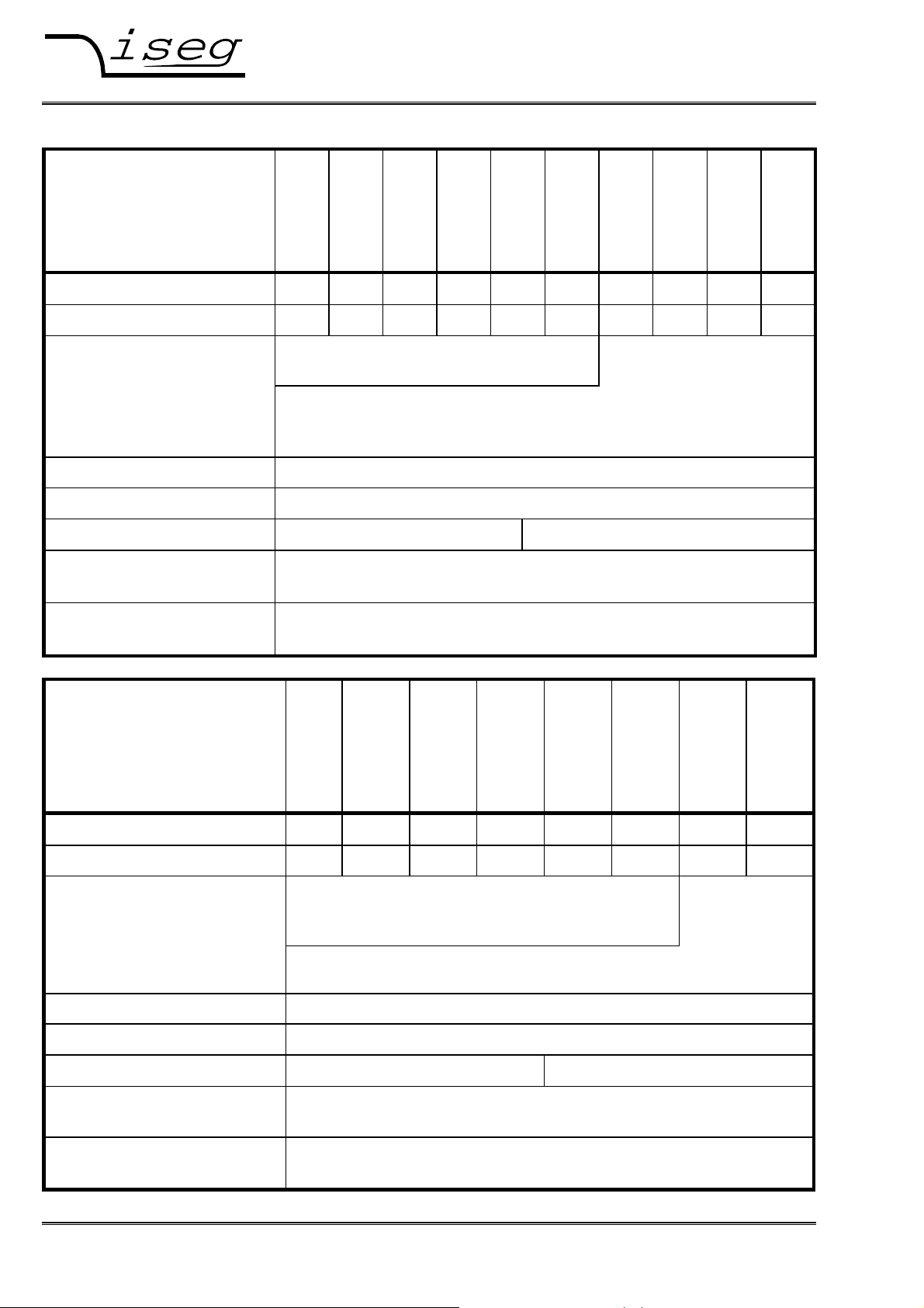
2 Technical data
19“ / 1U - series
HPx)1 300 W
10 307
)1
)1
HPx
Output voltage V
Output current I
HV connector
NOM
NOM
(kV)
(mA)
1 2 3 4 6 8 12 15 20 30
300 150 100 75 50 35 25 20 15 10
SHV front side, opt. rear side (SHV-R)
8 kV < V
V
Attention: Use with connected HV connector only !
Output power max. 300 W
Polarity
Ripple & noise [V
Voltage stability
P-P
]
factory fixed ⇒ )1x = p: positive ⇒ )1x = n: negative
V
≤ 8kV: < 1 • 10-4 • V
NOM
< 1 • 10-4 • V
in the output voltage range:
Current stability
< 2 • 10-3 • I
in the output voltage range:
20 157
HPx
30 107
)1
HPx
40 756
)1
HPx
60 506
)1
HPx
80 356
)1
HPx
120 256
)1
HPx
Lemo-HV-connector
rear side
≤ 16kV: Lemo ERA.1Y.416.CLL
NOM
> 16kV: Lemo ERA.3Y.425.CLL
NOM
V
NOM
(load to no load, ∆VIN and repeatability)
NOM
1% • V
( R
NOM
≤ RL < no load and ∆VIN)
Lmin
1% • V
> 8kV: < 5 • 10-4 • V
NOM
NOM
NOM
≤ V
≤ V
OUT
OUT
≤ V
≤ V
)1
NOM
NOM
150 206
HPx
200 156
)1
HPx
NOM
300 106
)1
HPx
19“ / 1U - series
HPx)1 800 W
Output voltage V
Output current I
HV connector
NOM
NOM
(kV)
(mA)
10 807
)1
HPx
20 407
)1
HPx
1 2 3 4 6 8 12 15
800 400 250 200 130 100 65 50
SHV front side, opt. rear side (SHV-R)
8 kV < V
Attention: Use with connected HV connector only !
Output power max. 800 W
Polarity
Ripple & noise [V
Voltage stability
P-P
]
factory fixed ⇒ )1x = p: positive ⇒ )1x = n: negative
V
≤ 8kV: < 1 • 10-4 • V
NOM
< 1 • 10-4 • V
in the output voltage range:
Current stability
< 2 • 10-3 • I
in the output voltage range:
30 257
)1
HPx
(load to no load, ∆VIN and repeatability)
NOM
( R
NOM
40 207
)1
HPx
NOM
V
NOM
1% • V
≤ RL < no load and ∆VIN)
Lmin
1% • V
60 137
)1
)1
HPx
≤ 16kV: Lemo ERA.1Y.416.CLL
> 8kV: < 5 • 10-4 • V
NOM
NOM
NOM
≤ V
≤ V
OUT
OUT
≤ V
≤ V
80 107
HPx
NOM
NOM
120 656
)1
HPx
Lemo-HVconnector
rear side
NOM
150 506
)1
HPx
iseg Spezialelektronik GmbH Email: sales@iseg-hv.de Tel ++ 49 (0)351 / 26 996 - 0
Bautzner Landstr. 23 http://www.iseg-hv.de Fax ++ 49 (0)351 / 26 996 - 21
4 D - 01454 Radeberg / Rossendorf
Page 5

Spezialelektronik GmbH
19“ / 1U - series LPx)1 300 W
Output voltage V
Output current I
HV connector
(kV) 1 2 3 4 6 8 12 15 20 30
NOM
(mA) 300 150 100 75 50 35 25 20 15 10
NOM
10 307
)1
LPx
SHV front side, opt. rear side (SHV-R)
8 kV < V
V
20 157
)1
LPx
30 107
)1
LPx
40 756
)1
LPx
60 506
)1
LPx
≤ 16kV: Lemo ERA.1Y.416.CLL
NOM
> 16kV: Lemo ERA.3Y.425.CLL
NOM
Attention: Use with connected HV connector only !
Output power max. 300 W
Discharge frequency Max. one complete discharge per second,
at discharging up to 2 kV against GND: up to 15 Hz
at discharging up to 1 kV against GND: up to 60 Hz
discharge current must be limited external to I
Polarity
Voltage stability
Current stability
factory fixed ⇒ )1x = p: positive ⇒ )1x = n: negative
< 1 • 10-3 • V
in the output voltage range: 5 V ≤ V
< 2 • 10-3 • I
in the output voltage range: 5 V ≤ V
(load to no load, ∆VIN and repeatability)
NOM
≤ V
OUT
(R
NOM
≤ RL < no load and ∆VIN)
Lmin
≤ V
OUT
80 356
)1
LPx
120 256
)1
LPx
150 206
)1
LPx
200 156
)1
LPx
300 106
)1
LPx
Lemo-HV-connector rear
side
otherwise
NOM
NOM
NOM
19“ / 1U - series LPx)1 800 W
Output voltage V
Output current I
HV connector
10 807
)1
LPx
(kV) 1 2 3 4 6 8 12 15
NOM
(mA) 800 400 250 200 130 100 65 50
NOM
20 407
)1
LPx
30 257
)1
LPx
40 207
)1
LPx
60 137
)1
LPx
SHV front side, opt. rear side (SHV-R)
80 107
)1
LPx
120 656
)1
LPx
150 506
)1
LPx
Lemo-HV-connector rear side ERA.1Y.416.CLL
Attention: Use with connected HV connector only !
Output power max. 800 W
Discharge frequency Max. one complete discharge per second,
at discharging up to 2 kV against GND: up to 15 Hz
at discharging up to 1 kV against GND: up to 60 Hz
Polarity
Voltage stability
Current stability
discharge current must be limited external to I
factory fixed ⇒ )1x = p: positive ⇒ )1x = n: negative
< 1 • 10-3 • V
in the output voltage range: 5 V ≤ V
< 2 • 10-3 • I
in the output voltage range: 5 V ≤ V
(load to no load, ∆VIN and repeatability)
NOM
≤ V
OUT
(R
NOM
≤ RL < no load and ∆VIN)
Lmin
≤ V
OUT
otherwise
NOM
NOM
NOM
iseg Spezialelektronik GmbH Email: sales@iseg-hv.de Tel ++ 49 (0) 351 / 26 996 - 0
Bautzner Landstr. 23 http://www.iseg-hv.de Fax ++ 49 (0) 351 / 26 996 - 21
D - 01454 Radeberg / Rossendorf 5
Page 6

Spezialelektronik GmbH
2.1 General technical data
19“ / 1U - series
HPx)1 300 W
Accuracy voltage measurement
current measurement
Temperature coefficient
19“ / 1U - series
HPx)1 800 W
± (0,5% • V
± (0,1% • I
< 2 • 10-4/
+ 0,3% • V
OUT
+ 0,05% • I
OUT
K
19“ / 1U – series
LPx)1 300 W
+ 1 digit) for one year
NOM
+ 1 digit) for one year
NOM
19“ / 1U – series
LPx)1 800 W
Display 8-digit LCD-Display for current and voltage
Resolution of voltage and current
4-digit
measurement
Resolution of settings LOCAL 4-digit
Voltage / Current REMote 4-digit
Switching of output voltage with button “ON/OFF” or via remote control
Control LOCAL rotary encoders for voltage and current
(REMote) CAN via CAN-Interface
USB via USB-Interface
optional: RS-232 via RS232-Interface
optional: AIF via indirect coupled analogue I/O additionally (male SUB-D-9)
optional: IEEE-488 via IEEE-Interface additionally (male Micro D25)
optional: ETH via Ethernet-Interface additionally (RJ45)
Efficiency up to 85%
Supply VIN = 85 up to 260 V AC with PFC
IIN = 1,7 A at 230V-AC / 3,5 A at 115 V-AC (300 W series),
IIN = 4,5 A at 230 V AC / 9 A at 115 V AC (600 W series)
via mains connector and switch “POWER“, isolated from HV-output,
fused with 2 • 6,3 A / slow (300 W series)
2 • 10 A / slow (800 W series).
Dimension 1U -19“ compatible / depth: 410 mm
Weight ca. 5,7 kg (300 W series) / ca. 6,5 kg (800 W series)
Cooling Internal fan
Protection Over load and short circuit , voltage supply and temperature
Environment conditions Operating temperature: 5 up to 35 °C
Humidity: 30% up to 80 %, no condensation
Storage temperature 0 up to 60 °C
iseg Spezialelektronik GmbH Email: sales@iseg-hv.de Tel ++ 49 (0)351 / 26 996 - 0
Bautzner Landstr. 23 http://www.iseg-hv.de Fax ++ 49 (0)351 / 26 996 - 21
6 D - 01454 Radeberg / Rossendorf
Page 7

Spezialelektronik GmbH
3 Functional description
The High Voltage PS of the HPx)1 - 300 W series provide an output voltage of 0 up to 30 kV-DC at
max. 300 W output power.
The High Voltage PS of the HPx)1 - 800 W series provide an output voltage of 0 up to 15 kV-DC at
max. 800 W output power.
The control loop is designed to provide a constant voltag or current.
The High Voltage PS of the LPx)1 - 300 W series provide an output voltage of 0 up to 30 kV-DC at
max. 300 W output power.
The High Voltage PS of the LPx)1 - 800 W series provide an output voltage of 0 up to 15 kV-DC at
max. 800 W output power. Mains voltage is 85 - 264 V -AC 50/60 Hz (PFC is standard).
The control loop is designed to charge a capacity in constant current control mode. This capacity will
discharge with the user circuit. You will find information to the discharge frequency dependence on
the discharge level in chapter 2.
On LPS devices, the Software voltage ramp (0…3000V/s) can be disabled. The device then ramps to
the choosen set voltages as fast as possible (see chapter 4 “Front panel operation” and 6 “Command
sets”).
Mains voltage is 85 to 260 V-AC 50/60 Hz.
The output voltage and current are limited due to the hardware circuitry. The polarity is factory fixed
)1
(
x=p: positive; )1x=n: negative).
The shield of the HV output is always connected to the housing ( ⊥⊥⊥⊥/PE-connector).
If this shield is intended to use as “reverse line“, then a jumper has to be plugged between the “0 V“
(reverse current) and the “⊥⊥⊥⊥/PE” connector.
If this jumper has been removed an additional “reverse line“ from the load to the “0 V“ connector must
been used and this connector close to ground can be float up to max. ± 300 V.
Attention: In this case the user is responsible that – due to the voltage between “0 V“ and
“⊥⊥⊥⊥/PE“ connector – no danger for the user may occur.
If the potential between “0 V“ and “⊥⊥⊥⊥/PE“ connector is > 300V then – in order to avoid damages for
the unit – the connections are short circuited with help of internal electronically protection circuits.
iseg Spezialelektronik GmbH Email: sales@iseg-hv.de Tel ++ 49 (0) 351 / 26 996 - 0
Bautzner Landstr. 23 http://www.iseg-hv.de Fax ++ 49 (0) 351 / 26 996 - 21
D - 01454 Radeberg / Rossendorf 7
Page 8
Spezialelektronik GmbH
3.1 Operation states
The device has the following operation states:
- POWER-ON Device initialises the connected Hardware (Booting)
- LOCAL Device is controlled with buttons and rotary encoders at the front panel
- REMOTE Device is remote controlled via interface (CAN, RS-232, IEEE-488)
The states LOCAL and REMOTE are further divided into:
- HV-OFF No high voltage is produced
- HV-ON High voltage according to Set values is produced
In the HV-ON state there are two modes for high voltage creation:
1. Voltage control CV:
Control of output voltage according to set value V
(Output current I
OUT
< I
), LED „CV“ lighting.
SET
2. Current control CC (only with “Kill disable”):
Control of output current according to set value I
(Output current V
OUT
< V
), LED „CC“ lighting.
SET
The KILL function is be set with the KILL/ESC button:
Disable: The output voltage will be limited after reaching I
Enable: The yellow LED „KILL ENABLE” is lighting.
The output voltage will be shut off permanently without ramp, if I
The re-setting of the output voltage is possible after pushing button HV ON again.
SET
SET
SET
≥ I
OUT
SET
.
3.2 Safety loop (Interlock)
The unit is equipped with a connector for a hardware safety loop (interlock) on the rear.
If the loop is closed an internal current source (open circuit voltage 15 V / short circuit current max.
40 mA) will drive a current of ca. 12 mA through the built-in safety relay.
That will work if the impedance of the closed loop is less than 200 Ohm.
If the safety loop is opened, the relay will be drop-out and the generation of high voltage will be
stopped without any semiconductor by the contacts of the safety relay only.
Caution: The internal and external capacities must be discharge about the load before the
output will be volt-free. The internal load is very high, so a very long discharging
time is possible according to the connected load.
The unit is not equipped with an active discharging circuit!
The safety loop is closed ex works with help of a wire strap.
It is not possible to switch on the high voltage generation if the loop is open.
If the loop will be closed again high voltage will be switch on with HV-ON on front panel or via the
digital interfaces only.
If chosen AIF ON in the menu F06 „Control with analogue I/O automatically“ it is able to switch
on high voltage with Low to High on the INHIBIT pin of the analogue I/O too.
iseg Spezialelektronik GmbH Email: sales@iseg-hv.de Tel ++ 49 (0)351 / 26 996 - 0
Bautzner Landstr. 23 http://www.iseg-hv.de Fax ++ 49 (0)351 / 26 996 - 21
8 D - 01454 Radeberg / Rossendorf
Page 9
Spezialelektronik GmbH
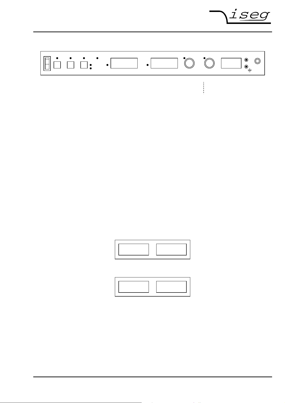
4 Front panel operation
POWER HV
1
O
KILL
REMOTE ERROR
ENABLE
ON
KILL
LOCAL
OFF
ESC
MENU
RxD
TxD
VOLTAGE CURRENT
CV CC
1.000kV 800.0mA
HIGH VOLTAGE POWER SUPPLY
VOLTAGE CURRENT HV OUT
iseg
HPp 10 807
1kV / 800mA
0 V
Picture: HPS/LPS front panel. Optional and if V
NOM
> 7 kV:
connections on the rear
After pushing the POWER button the device is booting. During boot, the integrated hardware is initialised. After start-up the device is working in LOCAL mode and the KILL function is “disable”.
In LOCAL mode, the set values for voltage and current can be adjusted with the rotary encoders
VOLTAGE for V
When trying to set V
and CURRENT for I
SET
SET
or I
beyond the adjusted limit, the corresponding LED is flashing for one
SET
. The yellow LEDs VOLTAGE and CURRENT are lighting.
SET
second.
Generation of high voltages starts by pushing the ON/OFF button. While generating high voltage, the
green LED “HV” is lighting.
Caution! The high voltage which has been selected with the rotary encoders is going to
ramp to the chosen voltage with the programmed ramp speed!
Factory setting for ramp speed is 0.2 •••• V
per second.
NOM
By pressing ON/OFF again, the high voltage generation is turned off, the green LED “HV” goes off.
The high voltage is ramped down with the programmed ramp speed.
4.1 Displays
The device has two eight digit displays for voltage and current as well as for Menu control.
In HV-OFF state, the set values are shown on display for easy changes with the rotary encoders
VOLTAGE and CURRENT. These set values are stored in processor’s EEPROM and reloaded at
next start-up.
While displaying the set values for voltage and current, a small ’s’ is flashing at the left display side:
s1.000kV s800.0mA
Picture: Set values on display in HV-OFF state
In HV-ON state the measured values of voltage and current are displayed:
0.995kV 752.3mA
Picture: Measured values on displays in HV-ON state
By pressing the rotary encoder VOLTAGE or CURRENT in HV-ON state, the corresponding set value
is displayed for a short time to allow exact adjustment.
If the set values aren’t changed, the device shows the measured values again after four seconds. By
pressing the corresponding rotary encoder again, this delay can be shortened.
After turning high voltage off, the displays show the measured values while ramping down. After four
seconds an with measured voltage lower than 60 V, the device shows the set values again.
iseg Spezialelektronik GmbH Email: sales@iseg-hv.de Tel ++ 49 (0) 351 / 26 996 - 0
Bautzner Landstr. 23 http://www.iseg-hv.de Fax ++ 49 (0) 351 / 26 996 - 21
D - 01454 Radeberg / Rossendorf 1
Page 10

Spezialelektronik GmbH
4.2 Menu
In HV-OFF mode the device menu is activated by pressing the button MENU.
If no button is pressed, the display switch back to HV-OFF mode after 30 seconds. The menu can
also be closed without changing any value by pressing the button ESC.
By turning the rotary encoder VOLTAGE you can scroll through the menu. By pressing the rotary encoder VOLTAGE the displayed menu point is selected. The setting can be changed by the active rotary encoder (shown by yellow LED). By pressing the active rotary encoder the changes are stored
and the main menu is displayed again.
Display Description
F01 Set Limit V
Adjust the Software voltage limit V
rotary encoder VOLTAGE. V
will be limited to this value.
SET
in the range of 0.02 • V
OUTmax
If the Limit gets smaller than the actual value of V
automatically.
SET
NOM
, V
will be decreased to V
SET
≤ V
OUTmax
≤ V
with
NOM
OUTmax
F02 Set Limit I
Adjust the Software current limit I
rotary encoder CURRENT. I
will be limited to this value.
SET
in the range of 0.02 • I
OUTmax
If the Limit gets smaller than the actual value of I
SET
≤ I
NOM
, I
will be decreased to I
SET
OUTmax
≤ I
with
NOM
OUTmax
auto-
matically.
F03 Set Ramp V Adjust voltage ramp speed with rotary encoder VOLTAGE in the range of 1…3000 V/s
(factory setting is 0.2 • V
NOM
/s).
On LPS devices, the software voltage ramp can be disabled. In this case, the device
changes it’s output voltage as fast as possible.
The software ramp can be disabled be setting the ramp speed greater than 3000 V/s:
“max.” will be displayed. To enable the software ramp again, set a ramp speed between
1…3000 V/s.
F04 Set Ramp I Adjust current ramp speed with rotary encoder CURRENT with the given values in the
range of 0.02 • I
NOM
/s up to I
/s (factory setting is I
NOM
NOM
/s)
F05 Auto Start Not implemented yet.
F06 Auto AIF AIF ON: Turn on HV by pushing the ON/OFF button or with
INHIBIT Low to High on analogue I/O
AIF OFF Turn on HV by pushing the ON/OFF button only
The INHIBIT signal on analogue I/O has priority in both cases!
INHIBIT High to Low: turn off HV
Low to High: turn on HV (KILL disable)
Low static: HV = 0
F07 Set Interfce Select external Interface with rotary encoder VOLTAGE:
“CAN” control via CAN-Interface
“RS-232” control via RS232-Interface
“USB“ control via USB-Interface
“IEEE 488” control via IEEE (GPIB)-Interface
“Ethernet“ control via Ethernet-Interface
“AIF” control via Analogue I/O
F08 Set Instruct Select instruction type for RS-232/USB/IEEE-488/Ethernet control with rotary encoder
VOLTAGE:
”EDCP” SCPI command set with EDCP (recommended)
“SCPI” old SCPI command set
“ET” old ET command set
F09 Addr IEEE Select IEEE address with rotary encoder VOLTAGE: 01 to 30. Factory setting is 17.
F10 Addr CAN Select CAN address with rotary encoder VOLTAGE: 00 to 63. Factory setting is 0.
iseg Spezialelektronik GmbH Email: sales@iseg-hv.de Tel ++ 49 (0)351 / 26 996 - 0
Bautzner Landstr. 23 http://www.iseg-hv.de Fax ++ 49 (0)351 / 26 996 - 21
2 D - 01454 Radeberg / Rossendorf
Page 11
Spezialelektronik GmbH
Display Description
F11 Set Echo
F12 Set Password The MENU settings are safed with 4 pin password. Setting position by position with rotary
Select Echo state for RS-232/USB control with rotary encoder VOLTAGE: “on” ⇒ “off” ⇒
“on”
encoder VOLTAGE. Given the code „0000“ the password function is not active (ex works).
F13 Show Power Change the display to V
and Power
OUT
(on/off)
OUT
F14 Quit Menu Close the menu.
4.3 Software limits
The device uses two software limits for voltage and current.
These limits consists of two functions:
1. Limit the set values to the adjusted limits: limit V
SET
to V
OUTmax
resp. I
SET
to I
OUTmax
.
2. Set the limit bits in Channel Status and Channel Event Status, if the measured values exceed
the limits:
- isVLIM and EVLIM if V
- isCLIM and ECLIM if I
OUT
OUT
≥ V
≥ I
OUTmax
OUTmax
+ 0.02 • V
+ 0.02 • I
NOM
NOM
In mode Kill enable, the bits EVLIM resp. ECLIM causes the High Voltage to shut down without ramp.
4.4 Error states
The following Events cause the High Voltage to shut down without ramp and have to be cleared with
Button KILL/ESC or a remote command (e. g. *CLS) before turning it on again.
Event Bit Display Description
EEMCY EMERGENCY OFF Emergency off via remote control
ETRIP CURRENT TRIP
Current trip (I
OUT
≥ I
) in mode Kill enable
SET
EVLIM VOLTAGE LIMIT Voltage limit exceeded in mode Kill enable
ECLIM CURRENT LIMIT Current limit exceeded in mode Kill enable
ESFLPngd SAFETYLOOP Safety loop was or is open
ETEMPngd OVERTEMPATURE Maximum allowed temperature was or is exceeded
iseg Spezialelektronik GmbH Email: sales@iseg-hv.de Tel ++ 49 (0) 351 / 26 996 - 0
Bautzner Landstr. 23 http://www.iseg-hv.de Fax ++ 49 (0) 351 / 26 996 - 21
D - 01454 Radeberg / Rossendorf 3
Page 12

Spezialelektronik GmbH
5 Interface control
For remote control, the corresponding interface (CAN, RS-232, USB, IEEE-488, Ethernet) has to be
selected first in Menu “F07 Set Interfce”. The device switches to REMOTE state when receiving the
first command from the selected interface. The yellow LED “REMOTE” is lighting. The yellow LEDs
VOLTAGE and CURRENT stop lighting to indicate that no local control is possible at the moment.
By pressing the LOCAL button the remote control is suspended. The device can now be controlled
via front panel. When receiving new commands via Interface, the device switches back to REMOTE
state.
If the device is in “HV-ON” state via interface, high voltage can be turned off by pressing the ON/OFF
button. In this case the device goes to LOCAL state as well.
Exception: If local control is disabled (Local Lockout, see chapter 6.3), the device can only
be turned off via mains switch POWER!
While receiving or transmitting data via RS-232 or IEEE-488, the LED’s RxD (Receiving) or TxD
(Transmitting) are flashing.
5.1 CAN Interface
Attention: Turn off the device with mains switch POWER before connecting/disconnecting
the interface cable.
The CAN interface is located at a male D-SUB-9 connector at the device rear. The pin assignment is
as follows:
Pin Signal
2 CAN_L (CAN Low)
3 CAN_GND (CAN Ground)
5 CAN_SHLD (CAN Shield)
7 CAN_H (CAN High)
For the CAN protocol, please see the description of the EDCP protocol in the manual
CAN-Interface
Multi-Channel High Voltage Power Supply Module
EHS xxx and EDS xxx
Thus, the device can be controlled with the program isegCANHVControl or with the iseg OPC server.
iseg Spezialelektronik GmbH Email: sales@iseg-hv.de Tel ++ 49 (0)351 / 26 996 - 0
Bautzner Landstr. 23 http://www.iseg-hv.de Fax ++ 49 (0)351 / 26 996 - 21
4 D - 01454 Radeberg / Rossendorf
Page 13

Spezialelektronik GmbH
5.2 RS-232- / USB Interface
Attention: Turn off the device with mains switch POWER before connecting/disconnecting
the interface cable.
Attention: If you device is equipped with RS-232 and USB Interface, only one of them must
be connected to the HPS at the same time.
RS-232
The RS-232 interface is located at a female D-SUB-9 connector at the device rear.
The electrical transfer is working indirectly coupled via RxD and TxD related to GND. The D-SUB-9
pin assignment is in the following table.
The cable connection to the computer is 1:1 (no zero modem-cable!). If no 9-pole cable is available,
then the connections shown in the table have to be made.
Signal HV-PS PC Connection
RS-232 D-SUB-9 Internal D-SUB-9 D-SUB-25 3-pol. cable
RxD 2 2 3
TxD 3 3 2
GND 5 5 7
4
6
8
─┐
─┤
─┘
4 20
6 6
8 5
─┐
─┤
─┘
USB
The USB interface is realized with a female USB-B connector at the device rear. Internal, the USB is
implemented as an USB-serial converter FTDI FT232R.
This device functions as virtual serial port in PC, and thus can be used with every program that supports a serial port, e. g. a terminal program or LabVIEW.
Programming
The following description applies both to RS-232 and USB interface.
For remote control, “RS-232” must be selected in Menu “F07 Set Interfce“. The device switches to
REMOTE state when receiving the first command via interface.
The (virtual) serial Interface is set to 9600 Bit/s, 8 Bit/character, no parity, 1 Stop-Bit.
The data transfer is character oriented, while the synchronization in direction "Computer to HV PS
unit” (Input direction) is made by echoes. The transfer direction “HV-PS to computer“ (Output direction) is free running.
The Echo can be permanently disabled (Factory setting is “Echo on“):
1. On front panel via Menu “F11 Set Echo“.
2. Via SCPI instruction set with EDCP
The command transfer works with ASCII code. Commands are terminated by <CR><LF> ($0D $0A
or 13 10). On input side, no leading zeros are needed. Output is fixed format without leading zero.
A minimum time delay of 20 ms between write and read instructions is needed.
iseg Spezialelektronik GmbH Email: sales@iseg-hv.de Tel ++ 49 (0) 351 / 26 996 - 0
Bautzner Landstr. 23 http://www.iseg-hv.de Fax ++ 49 (0) 351 / 26 996 - 21
D - 01454 Radeberg / Rossendorf 5
Page 14

Spezialelektronik GmbH
Windows USB driver installation
The FTDI VCP driver (Virtual COM Port) can be downloaded from:
http://www.iseg-hv.com Download Software USB driver for THQ/EHQ
The following steps are necessary for installation:
1. Extract the FTDI driver “CDM 2.04.16 WHQL Certified.zip“, e. g. to C:\Temp\
2. Connect the HV device to the computer via USB
3. The Found new Hardware wizard appears.
Please choose “No, not this time” in the first dialog and then click Next.
4. Choose “Install from a list or specific location” in the next dialog and then click Next:
iseg Spezialelektronik GmbH Email: sales@iseg-hv.de Tel ++ 49 (0)351 / 26 996 - 0
Bautzner Landstr. 23 http://www.iseg-hv.de Fax ++ 49 (0)351 / 26 996 - 21
6 D - 01454 Radeberg / Rossendorf
Page 15

Spezialelektronik GmbH
5. Please choose the directory you extracted the driver to and the click Next:
6. After some copying you get the final dialog:
It may be necessary to do the steps 3 to 6 again, before the device can be used
(the first time, a bus driver is installed, the second time, the virtual COM port driver is installed).
iseg Spezialelektronik GmbH Email: sales@iseg-hv.de Tel ++ 49 (0) 351 / 26 996 - 0
Bautzner Landstr. 23 http://www.iseg-hv.de Fax ++ 49 (0) 351 / 26 996 - 21
D - 01454 Radeberg / Rossendorf 7
Page 16

Spezialelektronik GmbH
RS-232/USB Interface Test under Windows
Determine the serial USB interface with Device Manager
Start the Device Manger with:
Start Settings Control Panel System Device Manager
All HPS devices with USB interface get an USB Serial Port assigned in section Ports (COM & LPT),
in this case COM3:
Test with HyperTerminal
HyperTerminal is included in Windows 2000 / XP and can be started with:
Start Programs Accessories Communications HyperTerminal
Create a new connection with menu „File New Connection“, name it e. g. “HPS” and click OK.
iseg Spezialelektronik GmbH Email: sales@iseg-hv.de Tel ++ 49 (0)351 / 26 996 - 0
Bautzner Landstr. 23 http://www.iseg-hv.de Fax ++ 49 (0)351 / 26 996 - 21
8 D - 01454 Radeberg / Rossendorf
Page 17

Spezialelektronik GmbH
The following dialog appears. Choose your serial port and click OK:
Please enter the interface parameters in the following dialog:
After clicking OK, the interface setup is finished.
iseg Spezialelektronik GmbH Email: sales@iseg-hv.de Tel ++ 49 (0) 351 / 26 996 - 0
Bautzner Landstr. 23 http://www.iseg-hv.de Fax ++ 49 (0) 351 / 26 996 - 21
D - 01454 Radeberg / Rossendorf 9
Page 18

Spezialelektronik GmbH
As last step, under:
File Properties Settings ASCII Setup
the setting “Send line ends with line feeds” has to be made (see following picture).
You can now test the communication with the device:
iseg Spezialelektronik GmbH Email: sales@iseg-hv.de Tel ++ 49 (0)351 / 26 996 - 0
Bautzner Landstr. 23 http://www.iseg-hv.de Fax ++ 49 (0)351 / 26 996 - 21
10 D - 01454 Radeberg / Rossendorf
Page 19

Spezialelektronik GmbH
5.4 IEEE-488 Interface (GPIB)
Attention: Turn off the device with mains switch POWER before connecting/disconnecting
the interface cable.
IEEE-488 Interface
The IEEE-488 bus interface was implemented with a NEC 7210 compatible IEEE controller. The following interface functions according to IEC 625 are available:
SH1 Source Handshake: all functions (no polling)
AH1 Acceptor Handshake: all functions (no polling)
T6 Talker: standard equipment
L4 Listener: standard equipment
To connect the device to the IEEE bus, a Micro-D25 male connector is located at the device rear. An
adapter cable with a 24 pin connector following IEEE-488.2 standard is available optional.
For remote control, the IEEE interface must be selected in Menu “F09 Set Interfce“ by choosing
“IEEE“. The IEEE address (0…30) can be selected in Menu “F11 Addr IEEE“. The device ships from
the factory with a IEEE address of 17.
When receiving control commands over IEEE, the device switches to REMOTE state and the yellow
LED “REMOTE” is lighting.
By pushing the LOCAL button, remote control is suspended and the device switches to LOCAL state.
If the device is in REMOTE state and high voltage is on, pushing ON/OFF turns off the HV generation
and the device switches to LOCAL state.
In both cases, when receiving new commands via interface, it switches back to REMOTE state.
Programming
The command transfer works with ASCII code. Commands are terminated by <CR><LF> ($0D $0A
or 13 10). Alternatively, the control line EOI (End or Identify) can be set together with the command’s
last character. On input side, no leading zeros are needed. Output is fixed format without leading
zero.
A minimum time delay of 5 ms between two IEEE commands is needed.
iseg Spezialelektronik GmbH Email: sales@iseg-hv.de Tel ++ 49 (0) 351 / 26 996 - 0
Bautzner Landstr. 23 http://www.iseg-hv.de Fax ++ 49 (0) 351 / 26 996 - 21
D - 01454 Radeberg / Rossendorf 11
Page 20

Spezialelektronik GmbH
5.5 Ethernet Interface
Attention: Turn off the device with mains switch POWER before connecting/disconnecting
the interface cable.
The Ethernet Interface with 10-MBit/s, Full-Duplex, is connected via RJ-45 socket on the device rear.
The device can be connected to a switch via patch cable. If it shall be connected to a PC directly, a
crossover cable has to be used.
“Ethernet” has to be set in menu “F09 Set Interfce“. The additional settings (IP address, net-mask,
default gateway) have to be made with the SCPI Instruction set with EDCP. This can be done over
Ethernet or RS-232. Ex works settings are as follows:
IP-address: 192.168.16.13
Net mask: 255.255.255.0
Default Gateway: 192.168.16.1
Command port: 10001 (fixed)
The connection can be tested with the ping command (Start programs accessories command).
C:\>ping 192.168.16.13
Ping will done for 192.168.16.13 with 32 bytes data:
Answer from 192.168.16.13: bytes=32 time=4ms TTL=128
Answer from 192.168.16.13: bytes=32 time=4ms TTL=128
Answer from 192.168.16.13: bytes=32 time=4ms TTL=128
Answer from 192.168.16.13: bytes=32 time=4ms TTL=128
Ping statistic for 192.168.16.13:
Package: sent = 4, received = 4, lost = 0
Time in millisecond:
minimum = 1ms, maximum = 4ms, average = 1ms
During communication the HV unit act as server, the control PC act as client. The following table
shows the principle sequence of communication PC to HV unit.
Step Function call Computer HV-Unit HV-Unit Computer
1. connect() SYN
2. SYN, ACK
3. ACK
4. send() "*IDN?\r\n"
5. recv() "iseg Spezialelektronik GmbH [...]"
6. closesocket() FIN, ACK
7. FIN, ACK
8. ACK
The first three packages are for the establishing of a TCP-Connection (three way handshake). Fourth
step is the inquiry from PC to HV unit. The order is ASCII coded in data field of the TCP packet. The
answer is also ASCII coded send to the PC in step 5. Package No. 6 confirms the receipt of the
packet and sends a FIN for termination of connection. Step 7 and 8 are the confirmation of termination of connection from HV unit and PC.
The communication can be monitored with a network sniffer (e. g. Wireshark). Control is done with
the instruction sets described later. The preferred command set for Ethernet is “SCPI with EDCP”, as
you can build longer Frames which reduces Ethernet Overhead.
iseg Spezialelektronik GmbH Email: sales@iseg-hv.de Tel ++ 49 (0)351 / 26 996 - 0
Bautzner Landstr. 23 http://www.iseg-hv.de Fax ++ 49 (0)351 / 26 996 - 21
12 D - 01454 Radeberg / Rossendorf
Page 21

Spezialelektronik GmbH
Programming
Simple programming example (without error handling) for communication with the HV device over
Ethernet. This program was compiled and tested with Microsoft Visual C++ 6.0 on Windows XP.
#include <stdio.h>
#include <winsock.h>
int main(int argc, char *argv[])
{
WSADATA wsadata;
SOCKET sock;
SOCKADDR_IN sockaddr_in;
int retcode;
char cmd[255] = "*IDN?\r\n";
char ans[255];
// init sockets (Berkeley style, UNIX compatible)
WSAStartup(2, &wsadata);
// create TCP socket
sock = socket(AF_INET, SOCK_STREAM, IPPROTO_TCP);
// bind socket to dynamic port
memset(&sockaddr_in, 0, sizeof(sockaddr_in));
sockaddr_in.sin_family = AF_INET; // UDP, TCP
sockaddr_in.sin_port = htons(10001); // Remote Port
sockaddr_in.sin_addr.S_un.S_un_b.s_b1 = 192; // IP address
sockaddr_in.sin_addr.S_un.S_un_b.s_b2 = 168;
sockaddr_in.sin_addr.S_un.S_un_b.s_b3 = 16;
sockaddr_in.sin_addr.S_un.S_un_b.s_b4 = 13;
// connect to server (three way handshake)
connect(sock, (SOCKADDR *)&sockaddr_in, sizeof(SOCKADDR_IN));
// send command to server
send(sock, cmd, strlen(cmd), 0);
// read answer from server
retcode = recv(sock, ans, sizeof(ans), 0);
// close socket (three way handshake) and clean up
closesocket(sock);
WSACleanup();
// print answer to screen
printf("%s\n", ans);
return 0;
}
iseg Spezialelektronik GmbH Email: sales@iseg-hv.de Tel ++ 49 (0) 351 / 26 996 - 0
Bautzner Landstr. 23 http://www.iseg-hv.de Fax ++ 49 (0) 351 / 26 996 - 21
D - 01454 Radeberg / Rossendorf 13
Page 22

Spezialelektronik GmbH
5.6 Analogue I/O Interface
Attention: Turn off the device with mains switch POWER before connecting/disconnecting
the interface cable.
Attention: All control inputs and outputs are indirect coupled to the HV-OUT.
All control inputs and outputs are available at the male D-SUB-9 connector on the rear side of the unit
according to the following table.
Analogue I/O with male SUB-D-9 connector
Pin 1 / 6 @GND Ground
Pin 2 V
Pin 3 INHIBIT TTL level / Input
Pin 4 V
Pin 5 Cmode TTL level / Output
Current monitor
I-MON
Current control
I-SET
Low = active: ⇒ V
High / offen: ⇒ V
= 0
OUT
according set values
OUT
Low = Current control (CC), High = Voltage control (CV)
reaction time < 100 ms
Pin 7 V
Pin 8 V
Pin 9 V
Voltage monitor
V-MON
Voltage control
V-SET
Internal reference voltage V
REF
= 5 V / 1 mA
REF
Operation with analogue I/O
You can choose control with the analogue interface “AIF” in the menu „F07 Set Interfce“ and then
switch push button “LOCAL” in order to switch to analogue remote control, the yellow LED “REM” is
lighting now (exception see “Auto AIF”).
By pushing LOCAL again the mode runs back to menu and „HV-OFF”. To use the unit in LOCAL
mode again you must choose an other interface in the menu „F07 Set Interfce” (e.g. RS-232).
The generation of high voltage will start with pushing “HV ON” (exception see “Auto AIF”) according
to the analogue set values and will stop with pushing “HV OFF” or with external INHIBIT (LOW = active).
The reaction to the active INHIBIT signal is according to the setting of the KILL function:
• KILL disable: generation of HV will be stopped, with Low to High on INHIBIT the output will be
ramp to the chosen voltage/current with the programmed ramp speed!
• KILL enable: generation of HV will be stopped, with Low to High on INHIBIT the output will be
volt-free. The generation of high voltage will start with pushing “HV ON” only
(exception see “Auto AIF”).
Automatic function “Auto AIF“
If the control mode is chosen with analogue interface “AIF” in the menu „F07 Set Interfce“ you can set
the automatic function “Auto AIF” in the menu „F06 Auto AIF“ to “ON”.
Now it is able to start the generation of HV according to the set values with the INHIBIT signal Low to
High, without pushing “HV ON”!
Caution! The high voltage generation will start with each Low to High Signal on INHIBIT!
If you choose an other interface in the menu „F07 Set Interfce“, the function “Auto AIF” will be set to
“OFF” automatically. If you will use „Auto AIF“ again, you must choose “AIF” in the menu „F07 Set
Interfce“ before and than set the automatic function “Auto AIF” in the menu „F06 Auto AIF“ to “ON”.
iseg Spezialelektronik GmbH Email: sales@iseg-hv.de Tel ++ 49 (0)351 / 26 996 - 0
Bautzner Landstr. 23 http://www.iseg-hv.de Fax ++ 49 (0)351 / 26 996 - 21
14 D - 01454 Radeberg / Rossendorf
Page 23
Spezialelektronik GmbH
Control inputs
• Remote Control Voltage (CV) V
= 0 to 5 V
V-SET
The output voltage is proportionally to the external control voltage of 0 to 5 V DC between
pin 8 (+ V
Example: HPp 40 357, maximum voltage = 4 kV
V
(V) Output voltage (kV)
V-SET
, indirect coupled) and pin 6 (@GND, indirect-coupled).
V-SET
5.0 corresponds to 4.0
2.5 corresponds to 2.0
1.0 corresponds to 0.8
• Remote Control Current (CC): V
The output current is proportionally to the external control voltage of 0 to 5 V DC between
pin 4 (+ V
, indirect coupled) and pin 6 (@GND, indirect-coupled).
I-SET
Example: HPp 40 357, maximum current = 350 mA
V
(V) Output current (mA)
I-SET
= 0 to 5 V
I-SET
5.0 corresponds to 350
2.5 corresponds to 175
1.0 corresponds to 70
• INHIBIT TTL level
High voltage generation will be shut off with help of the TTL-level LOW on pin 3 related to GND analogue (@GND-analogue indirect-coupled to GND-HV and metal box).
High voltage generation will be started according to the settings with TTL-level Low to High or open
on pin 3 in case of “KILL” is disabled. If “KILL” is enabled also the push button “HV-ON” has to be
pushed.
Monitor outputs
• Voltage monitor output V
An analogue monitor signal proportionally to the output voltage is available. This monitor voltage is
measured between pin 7 (V
, indirect-coupled) and pin 6 (@GND, indirect-coupled).
V-MON
Example: HPp 40 357, maximum output voltage = 4 kV
V
(V) Output voltage (kV)
V-MON
= 0 to 5 V
V-MON
5.0 corresponds to 4.0
2.5 corresponds to 2.0
1.0 corresponds to 0.8
• Current monitor output V
An analogue monitor signal proportionally to the output current is available. This monitor voltage is
measured between pin 2 (V
, indirect-coupled) and pin 6 (@GND, indirect-coupled).
I-MON
Example: HPp 40 357, maximum output current = 350 mA
V
(V) Output current (mA)
I-MON
= 0 to 5 V
I-MON
5.0 corresponds to 350
2.5 corresponds to 175
1.0 corresponds to 70
iseg Spezialelektronik GmbH Email: sales@iseg-hv.de Tel ++ 49 (0) 351 / 26 996 - 0
Bautzner Landstr. 23 http://www.iseg-hv.de Fax ++ 49 (0) 351 / 26 996 - 21
D - 01454 Radeberg / Rossendorf 15
Page 24

Spezialelektronik GmbH
6 Command sets
6.1 SCPI command set with EDCP
This is the recommended command Set.
To use this command set, choose “EDCP” in the menu or the *INSTR command. (EDCP = Enhanced
Device Communication Protocol). This command set is oriented on the iseg EDCP CAN Protocol with
Status and Event handling.
The Status and Event Status Fields are explained after the SCPI table.
Common Commands
*IDN?
*CLS
*RST
*LLO
*GTL
*INSTR?
*INSTR,EDCP
:VOLTage
<Voltage>[V] Set Channel Voltage
:LIMit <Voltage>[V]
:BOUnds <Voltage>[V]
{ ON | OFF }
EMCY OFF
EMCY CLR
:CURRent
<Current>[A] Set Channel Current
:LIMit <Current>[A]
:BOUnds <Current>[A]
:EVent
CLEAR
:MASK <Word>
:MEASure
:VOLTage?
:CURRent?
:CONFigure
:RAMP
:VOLTage <RampSpeed>[V/s]
:VOLTage MAX
:CURRent <RampSpeed>[A/s]
:EVent
:CLEAR
:MASK
:KILL?
:KILL { 0 | 1 }
)1, )2
If the high voltage is shut down with :VOLT EMCY OFF, the channel is hold in state Emergency Off. To turn
on the High Voltage again, the state Emergency Off must be leaved with :VOLT EMCY CLR. Furthermore, the
Channel EventStatus Bit EEMCY must be cleared e. g. with *CLS.
Query Module Identification
Clear Module (Event-)Status
Reset device to save values
(Turn HV off with ramp, Vset= 0, Iset= Inominal)
Local Lockout (disable front panel buttons)
Goto Local (enable front panel buttons)
Query instruction set
Switch to EDCP SCPI command set
SCPI Commands
Set Voltage Limit
Set Channel Voltage Bounds
Set Channel On / Off (with configured ramp speed)
Shut Channel Emergency Off (without ramp)
Leave state emergency off
Set Current Limit
Set Channel Current Bounds
Clear Channel Event Status
Set Channel Event Mask
Query Measured Channel Voltage (V)
Query Measured Channel Current (A)
Set/Get module configuration
Set Module Voltage Ramp Speed
LPS only: disable Software Voltage Ramp
Set Module Current Ramp Speed
Clear Module Event Status
Query Module Kill Status
Set Kill Disable (0) or Kill Enable (1)
iseg Spezialelektronik GmbH Email: sales@iseg-hv.de Tel ++ 49 (0)351 / 26 996 - 0
Bautzner Landstr. 23 http://www.iseg-hv.de Fax ++ 49 (0)351 / 26 996 - 21
16 D - 01454 Radeberg / Rossendorf
Page 25

Spezialelektronik GmbH
:CONFigure
:ETHernet
:ADDRess <xxx.xxx.xxx.xxx>
:ADDRess?
:NETmask <xxx.xxx.xxx.xxx>
:NETmask?
:GATEway <xxx.xxx.xxx.xxx>
:GATEway?
:MAC?
:SERIAL
:BAUDrate?
:ECHO { 0 | 1 }
:ECHO?
:GPIB
:ADDRess?
:CAN
:ADDRess?
:READ
:VOLTage?
:LIMit?
:NOMinal?
:BOUnds?
:CURRent?
:LIMit?
:NOMinal?
:BOUnds?
:RAMP
:VOLTage?
:CURRent?
:MODule
:STATus?
:EVent
:STATus?
:MASK?
:SUPply?
:TEMPerature?
:CHANnel
:STATus?
:EVent
:STATus?
:MASK?
Set Ethernet IP Address
Query Ethernet IP Address
Set Ethernet IP Netmask
Query Ethernet IP Netmask
Set Ethernet IP Default Gateway
Query Ethernet IP Default Gateway
Query Ethernet MAC Address
RS-232/USB Configuration
Query Serial Baudrate
Set Serial Echo Off (0) or Echo On (1)
Query Serial Echo
Query IEEE-488/GPIB Address
Query CAN Address
Query Set Voltage (V)
Query Voltage Limit (V)
Query Nominal Voltage (V)
Query Voltage Bounds (V)
Query Set Current (A)
Query Current Limit (A)
Query Nominal Current (A)
Query Current Bounds (A)
Query Voltage Ramp Speed (V/s)
Query Current Ramp Speed (A/s)
Query Module Status Word
Query Module Event Status
Query Module Event Mask
Query Module Supply State
(1 = good, 0 = not good)
Query measured Module Temperature (°C)
Query Channel Status Word
Query Channel Event Status Word
Query Channel Event Status Mask
iseg Spezialelektronik GmbH Email: sales@iseg-hv.de Tel ++ 49 (0) 351 / 26 996 - 0
Bautzner Landstr. 23 http://www.iseg-hv.de Fax ++ 49 (0) 351 / 26 996 - 21
D - 01454 Radeberg / Rossendorf 17
Page 26

Spezialelektronik GmbH
Output formats for voltage and current:
Vnominal Output format voltage values
100 V ≤ V
1 kV ≤ V
10 kV ≤ V
< 1 kV 123.456V
nom
< 10 kV 1.23456E3V
nom
< 100 kV 12.3456E3V
nom
Inominal Output format current values
1 mA ≤ I
10 mA ≤ I
100 mA ≤ I
1 A ≤ I
10 A ≤ I
< 10 mA 1.23456E-3A
nom
< 100 mA 12.3456E-3A
nom
< 1 A 123.456E-3A
nom
< 10 A 1.23456A
nom
< 100 A 12.3456A
nom
Examples:
Read Module Identification:
*IDN?
iseg Spezialelektronik GmbH,HPp 40 207,680001,5.24
Set Voltage to 1000.501 V
:VOLT 1000.501
Set Current to 1.58 mA
:CURR 0.00158
Set Voltage Ramp speed to 300 Volt per second
:CONF:RAMP:VOLT 300
Advanced Examples:
Set and read back Voltage and Current:
:VOLT 2000.5; :READ:VOLT?; :CURR 0.2; :READ:CURR?
2.00050E3V;200.000E-3A
Read actual measured Voltage and Current:
:MEAS:VOLT?; CURR?
2.00028E3V;19.997E-3A
iseg Spezialelektronik GmbH Email: sales@iseg-hv.de Tel ++ 49 (0)351 / 26 996 - 0
Bautzner Landstr. 23 http://www.iseg-hv.de Fax ++ 49 (0)351 / 26 996 - 21
18 D - 01454 Radeberg / Rossendorf
Page 27

Spezialelektronik GmbH
Channel status (read access)
:READ:CHANnel:STATus?
Bit15 Bit14 Bit13 Bit12 Bit11 Bit10 Bit9 Bit8
isVLIM isCLIM isTRP isEINH isVBND isCBND res res
Bit7 Bit6 Bit5 Bit4 Bit3 Bit2 Bit1 Bit0
isCV isCC isEMCY isRAMP isON isIERR res res
The ChannelStatus register describes the actual status. Depending on the status of the channel the
bits will be set or reset.
Bit Name Bit is 1 Bit is 0
isVLIM IsVoltageLimitExceeded Voltage limit set by V
IsCLIM IsCurrentLimitExceeded Current limit set by I
Trip is set when Voltage or Current
isTRIP IsTripExceeded
isEINH IsExtInhibit External Inhibit active No External Inhibit
isVBND IsVoltageBoundsExceeded Voltage out of bounds Voltage in bounds
isCBND IsCurrentBoundsExceeded Current out of bounds Current in bounds
IsCV IsControlledVoltage
IsCC IsControlledCurrent
isEMCY IsEmergencyOff Emergency off without ramp No Emergency Off
isON IsOn HV is On HV is Off
isRAMP IsRamping Ramp is running No Ramp is running
isIERR InputError Input error No Input error
res Reserved
limit or Iset has been exceeded
(when KillEnable=1)
Voltage control active (evaluation is
guaranteed when no ramp is running)
Current control active (evaluation is
guaranteed when no ramp is running)
is exceeded Voltage limit not exceeded
max
is exceeded Current limit not exceeded
max
No Trip
Voltage control not active
Current control not active
iseg Spezialelektronik GmbH Email: sales@iseg-hv.de Tel ++ 49 (0) 351 / 26 996 - 0
Bautzner Landstr. 23 http://www.iseg-hv.de Fax ++ 49 (0) 351 / 26 996 - 21
D - 01454 Radeberg / Rossendorf 19
Page 28

Spezialelektronik GmbH
Channel event status (read/write access)
:READ:CHANnel:EVent:STATus?
Bit15 Bit14 Bit13 Bit12 Bit11 Bit10 Bit9 Bit8
EVLIM ECLIM ETRP EEINH EVBNDs ECBNDs res res
Bit7 Bit6 Bit5 Bit4 Bit3 Bit2 Bit1 Bit0
ECV ECC EEMCY EEOR EOn2Off EIER res Res
The Channel EventStatus register describes the captured status. Depending on the status of the
channel the bits will be set but not reset. A reset has to be done by the user by writing an 1 to this
event bit. All Events can be cleared by :EVENT:CLEAR.
Bit Name
EVLIM EventVoltageLimit Event: Voltage limit has been exceeded
ECLIM EventCurrentLimit Event: Current limit has been exceeded
Description
ETRIP EventTrip
Event: Trip is set when Voltage or Current limit or Iset has been exceeded (when KillEnable=1)
EEINH EventExtInhibit Event: External Inhibit
EVBNDs EventVoltageBounds Event: Voltage out of bounds
ECBNDs EventCurrentBounds Event: Current out of bounds
ECV EventControlledVoltage Event: Voltage control
ECC EventControlledCurrent Event: Current control
EEMCY EventEmergencyOff Event: Emergency off
EEOR EventEndOfRamp Event: End of ramp
EOn2Off EventOnToOff Event: Change from state "On" to "Off" without ramp
EIER EventInputError Event: Input Error
res Reserved
An event bit is permanently set if the corresponding status bit is 1 or is changing to 1. Different to the
status bit an event bit isn't automatically reset. A reset has to be done by the user by writing an 1 to
this event bit.
If one of the EventStatus Bits EVLIM, ECLIM, ETRIP, EEINH, EVBNDs, ECBNDs, EEMCY is set, it
prevents turning on the High Voltage again until the corresponding bit is cleared.
iseg Spezialelektronik GmbH Email: sales@iseg-hv.de Tel ++ 49 (0)351 / 26 996 - 0
Bautzner Landstr. 23 http://www.iseg-hv.de Fax ++ 49 (0)351 / 26 996 - 21
20 D - 01454 Radeberg / Rossendorf
Page 29

Spezialelektronik GmbH
ModuleStatus (read access)
:READ:MODule:STATus?
Bit15 Bit14 Bit13 Bit12 Bit11 Bit10 Bit9 Bit8
isKILena isTEMPgd isSPLYgd isMODgd isEVNTact isSFLPgd isnoRAMP isnoSERR
Bit7 Bit6 Bit5 Bit4 Bit3 Bit2 Bit1 Bit0
res res res isSrvc res res res isADJ
The status bits as there are IsTemperatureGood, IsSupplyGood, IsModuleGood, IsEventActive, IsSafetyLoopGood, IsNoRamp and IsNoSumError indicate the single status for the complete module.
Bit Name Bit is 1 Bit is 0
isKILena IsKillEnable Module is in state Kill enable Module is in state Kill disable
isTEMPgd IsTemperatureGood
isSPLYgd IsSupplyGood Power Supply is good Power Supply is not good
isMODgd IsModuleGood Module status is good Module status bad
isEVNTact IsEventActive At least one masked Event is active No masked Event is active
isSFLPgd IsSafetyLoopGood Safety Loop is closed Safety Loop is open
isnoRAMP IsNoRamp All channels stable, no ramp active. At least one channel is ramping
isnoSERR IsNoSumError No sum error Sum error active
isSrvc IsServiceNeeded
isADJ IsFineAdjustment Adjustment is on Adjustment is off
Res Reserved
Module Temperature < 55 °C Module temperature > 55°C
High voltage is turned off
Hardware failure detected:
consult manufacturer
No Hardware failure detected
iseg Spezialelektronik GmbH Email: sales@iseg-hv.de Tel ++ 49 (0) 351 / 26 996 - 0
Bautzner Landstr. 23 http://www.iseg-hv.de Fax ++ 49 (0) 351 / 26 996 - 21
D - 01454 Radeberg / Rossendorf 21
Page 30

Spezialelektronik GmbH
Module EventStatus (read/write access)
:READ:MODule:EVent:STATus?
The Module EventStatus register describes the captured status. Depending on the status of the module the bits will be set but not reset. A reset has to be done by the user by writing an 1 to this event
bit. All Events can be cleared by :CONFIGURE:EVENT:CLEAR.
Bit15 Bit14 Bit13 Bit12 Bit11 Bit10 Bit9 Bit8
Res ETMPngd ESPLYngd res res ESFLPngd res res
Bit7 Bit6 Bit5 Bit4 Bit3 Bit2 Bit1 Bit0
res res res res ESrvc res res res
ETEMPngd EventTemperatureNotGood Event: Temperature is above 55°C
ESPLYngd EventSupplyNotGood Event: at least one of the supplies is not good
ESFLPngd EventSafetyLoopNotGood Event: Safety loop is open
Event: A hardware failure of the HV module has been detected. The HV is
ESrvs EventService
res Reserved
switched off without the possibility to switch on again. Please consult the
iseg Spezialelektronik GmbH.
iseg Spezialelektronik GmbH Email: sales@iseg-hv.de Tel ++ 49 (0)351 / 26 996 - 0
Bautzner Landstr. 23 http://www.iseg-hv.de Fax ++ 49 (0)351 / 26 996 - 21
22 D - 01454 Radeberg / Rossendorf
Page 31

Spezialelektronik GmbH
6.2 ET command set (Compatibility to old HPS)
This command set is selected via Menu “F10 Set Instruct” “ET”.
Setting commands
Command: Command example:
Command to set an output voltage:
U,<Voltage>kV U,1.000kV
Command to set a voltage limit:
UL,<Voltage>kV UL,1.000kV
Command to set an output current:
I,<Current>mA I,30mA
Command to set a current limit:
IL,<Current>mA IL,30mA
Command to set the Voltage ramp speed:
RAMP,<Rampspeed>V/s RAMP,3000V/s
Command to switch the high voltage on and off:
HV,ON
HV,OFF
Command for setting the KILL function „Enable“ or „Disable“:
KILL,ENable KILL,EN
KILL,DISable
Command for Emergency off (The HV generation is shut off permanently and the set values for voltage and current are set to Zero):
EMCY OFF
Read out the setting commands
Command: Response example:
Read out the set voltage:
STATUS,U U, RANGE=3.000kV, VALUE=2.458kV
Read out the voltage limit:
STATUS,UL UL, RANGE=3.000kV, VALUE=2.458kV
Read out the set current:
STATUS,I I, RANGE=100.0mA, VALUE=30.0mA
Read out the current limit:
STATUS,IL IL, RANGE=100.0mA, VALUE=30.0mA
Read out the voltage ramp speed:
STATUS,RAMP RAMP, RANGE=3000V/s, VALUE=1000V/s
iseg Spezialelektronik GmbH Email: sales@iseg-hv.de Tel ++ 49 (0) 351 / 26 996 - 0
Bautzner Landstr. 23 http://www.iseg-hv.de Fax ++ 49 (0) 351 / 26 996 - 21
D - 01454 Radeberg / Rossendorf 23
Page 32

Spezialelektronik GmbH
Read out the measurement values
Read measured output voltage:
STATUS,MU UM, RANGE=3.000kV, VALUE=2.458kV
Read measured output current:
STATUS,MI IM, RANGE=100.0mA, VALUE=25.3mA
Read out the device status
STATUS,DI DI, b
15 b14 b13 b12 b11 b10 b9 b8 b7 b6 b5 b4 b3 b2 b1 b0
0 1
#define IERR b15 no Input Error Input error
#define RAMP b14 no Ramp Ramp
#define EMCY b13 no Emergency Emergency
#define TRIP b12 no Trip error Trip error
#define RES5 b11 Reserved
#define RES4 b10 Reserved
#define RES3 b9 Reserved
#define RES2 b8 Reserved
#define SERR b7 no Sum error Sum error
#define IREG b6 no Current control Current control
#define VREG b5 no Voltage control Voltage control
#define POL b4 negative Polarity positive Polarity
#define INH b3 no external Inhibit external Inhibit
#define RES1 b2 Reserved
#define KILena b1 Kill disable Kill enable
#define ON b0 no High voltage active High voltage active
Read out the LAM status
STATUS,LAM
LAM,ERROR External Inhibit occurred during Kill enable
LAM,EMERGENCY High Voltage was shut down with Emergency Off
LAM,SAFETY LOOP Safety Loop was opened
LAM,INHIBIT External Inhibit occurred
LAM,TRIP ERROR Software current trip occurred
LAM,VOLTAGE LIMIT Voltage has exceeded set value
LAM,CURRENT LIMIT Current has exceeded set value
LAM,INPUT ERROR Wrong command received
LAM,OK Status OK
Read out the device identification
ID ID, iseg Spezialelektronik r5.01 sn.680041 Typ HPn 30 107
iseg Spezialelektronik GmbH Email: sales@iseg-hv.de Tel ++ 49 (0)351 / 26 996 - 0
Bautzner Landstr. 23 http://www.iseg-hv.de Fax ++ 49 (0)351 / 26 996 - 21
24 D - 01454 Radeberg / Rossendorf
Page 33

Spezialelektronik GmbH
6.3 SCPI command set (Compatibility to old HPS)
This instruction set ist selected with Menu “F10 Set Instruct“ “SCPI“.
Setting commands
Command: Command example:
Command to set an output voltage:
:VOLTage <Voltage>kV :VOLT 1.000kV
Command to set a voltage limit:
:LIMIT:VOLTage <Voltage>kV :LIMIT:VOLT 1.000kV
Command to set an output current:
:CURRent <Current>mA :CURR 30mA
Command to set a current limit:
:LIMIT:CURRent <Current>mA :LIMIT:CURR 30mA
Command to set a voltage ramp speed:
:CONFigure:RAMP <Rampspeed>V/s :CONF:RAMP 3000V/s
Command to turn high voltage on and off:
:VOLTage ON
:VOLTage OFF
Command for Emergency off (The HV generation is shut off permanently and the set values for voltage and current are set to Zero):
:VOLTage EMCY OFF
Command for setting KILL function “Enable“ or “Disable“:
:CONFigure:KILL ENable :CONF:KILL EN
:CONFigure:KILL DISable
Read out the setting commands
Command: Response example:
Command to read out the set voltage:
:READ:VOLTage? U, RANGE=3.000kV, VALUE=2.458kV
Command to read out the voltage limit:
:READ:LIMIT:VOLTage? UL, RANGE=3.000kV, VALUE=2.458kV
Command to read out the set current:
:READ:CURRent? I, RANGE=100.0mA, VALUE=30.0mA
Command to read out the current limit::
:READ:LIMIT:CURRent? IL, RANGE=100.0mA, VALUE=30.0mA
Command to read out the voltage ramp speed:
:READ:RAMP? Ramp, RANGE=3000V/s, VALUE=3000V/s
iseg Spezialelektronik GmbH Email: sales@iseg-hv.de Tel ++ 49 (0) 351 / 26 996 - 0
Bautzner Landstr. 23 http://www.iseg-hv.de Fax ++ 49 (0) 351 / 26 996 - 21
D - 01454 Radeberg / Rossendorf 25
Page 34

Spezialelektronik GmbH
Read out the measurement values
Read measured output voltage:
:MEASure:VOLTage? UM, RANGE=3.000kV, VALUE=2.458kV
Read measured output current:
:MEASure:CURRent? IM, RANGE=100.0mA, VALUE=25.3mA
Read out the device status
:READ:STATus? DI, b
15 b14 b13 b12 b11 b10 b9 b8 b7 b6 b5 b4 b3 b2 b1 b0
For status field description, see chapter 6.1, device status.
Read out the LAM status
:READ:LAM?
For LAM status description, see chapter 6.1, LAM status.
Read out the device identification
:READ:IDNT? ID, iseg Spezialelektronik r5.01 sn.680042 Typ HPn 30 107
6.4 Common command set (Compatibility to old HPS)
The Common commands can be used all the time, independently from selected instruction set (ET or
SCPI).
A response example for commands that returns an answer is shown at the right side (printed Italic).
Command Response example:
Read out the device identification
*IDN? ID, iseg Spezialelektronik r5.01 sn.680043 Typ HPn 30 107
Device control
*LLO Local Lockout: disable local buttons
*GTL Go to Local: enable local buttons
*CLS Clear Status: clear error status
*RST Reset: Device is rebooting
Read/change Instruction set
*INSTR? Query current instruction set Instruction type, SCPI
*INSTR,SCPI Change to SCPI instruction set
*INSTR,ET Change to ET instruction set
Read/change RS-232 Echo state
*ECHO? Query Echo status Echo off
*ECHO*ON Turn on Echo
*ECHO*OFF Turn off Echo
iseg Spezialelektronik GmbH Email: sales@iseg-hv.de Tel ++ 49 (0)351 / 26 996 - 0
Bautzner Landstr. 23 http://www.iseg-hv.de Fax ++ 49 (0)351 / 26 996 - 21
26 D - 01454 Radeberg / Rossendorf
Page 35

Spezialelektronik GmbH
7 Troubleshooting
7.1 Error messages on Displays
Error messages during operation
Display: Meaning:
SAFETYLOOP Safety loop (Interlock) is not closed. Device can’t create high voltage.
EXTERNAL INHIBIT No high voltage can be created because of external inhibit (analogue I/O).
EMERGENCY High voltage has been shut down without ramp due to Emergency Off.
CURRENT TRIP Current set value reached during Kill enable. High voltage has been shut
down without ramp.
VOLTAGE LIMIT Voltage Limit V
has been exceeded.
max
In Kill enable, the high voltage is shut down without ramp.
CURRENT LIMIT Current Limit I
has been exceeded.
max
In Kill enable, the high voltage is shut down without ramp.
OVERTEMPERATURE High voltage has been shut down because of over temperature.
Let device cool down.
ERROR SUPPLY Internal power supply is bad. Device must be shipped to service.
ERROR SERVICE High voltage generator is bad. Device must be shipped to service.
Error messages during boot
Display: Meaning:
ERROR RTC Real time clock battery is low. Contact service.
CONTACT SERVICE Device must be shipped to the factory for service.
ERROR AIF Analogue interface (optional) is not working. Contact service.
ERROR IEEE IEEE interface (optional) is not working. Contact service.
7.2 General errors
Unit does not provide output voltage, and
the displays are not lighting
⇒
- check mains voltage and connection
Unit does not provide output voltage but
the displays are ligthing.
During switch ON external fuses are
blowing
If these provisions do not lead to a good result, this unit has to be checked from an authorised
agent or must be shipped to the factory.
iseg Spezialelektronik GmbH Email: sales@iseg-hv.de Tel ++ 49 (0) 351 / 26 996 - 0
Bautzner Landstr. 23 http://www.iseg-hv.de Fax ++ 49 (0) 351 / 26 996 - 21
D - 01454 Radeberg / Rossendorf 27
⇒
⇒
- Check of environmental temperature
(TA ≤ 35 °C)
- Check of Control
- Replace to slow blow fuse (switch ON
current peak 25 A)
 Loading...