

Page 1

Spezialelektronik GmbH
iseg c/o ROTECH Email: sales@iseg-hv.de Phone ++ 49 351 / 26 95 - 260
Spezialelektronik Bautzner Landstr. 45 http://www.iseg-hvcom Fax ++ 49 351 / 26 95 - 261
GmbH D - 01454 Rossendorf Germany
9-channel High Voltage Power Supply EHQ 9005-F
Operators Manual
Contents
1. General information
2. Technical data
3. Handling
4. Communication via interface
4.1 Device Protocol DCP
4.2 Overview about used CAN data frames
4.3 Detailed CAN data frames description
4.4 CAN-Bus implementation
Appendix A: Side view
Attention!
-The device must not be operated with the cover removed.
-We decline all responsibility for damages and injuries caused by an improper use of the
module. It is highly recommended to read the manual before any kind of operation.
Note
The information in this manual is subject to change without notice. We take no responsibility for any error in the
document. We reserve the right to make changes in the product design without reservation and without
notification to the users.
Filename EHQ9005F_V113.___; version 1.13 as of 2001-01-11
Page 2

Spezialelektronik GmbH
iseg c/o ROTECH Email: sales@iseg-hv.de Phone ++ 49 351 / 26 95 - 260
Spezialelektronik Bautzner Landstr. 45 http://www.iseg-hv.com Fax ++ 49 351 / 26 95 - 261
2 GmbH D - 01454 Rossendorf Germany
Page 3

Spezialelektronik GmbH
iseg c/o ROTECH Email: sales@iseg-hv.de Phone ++ 49 351 / 26 95 - 260
Spezialelektronik Bautzner Landstr. 45 http://www.iseg-hv.com Fax ++ 49 351 / 26 95 - 261
GmbH D - 01454 Rossendorf Germany 3
1. General information
The EHQ 9005-F is a 9-channel high voltage power supply in 6U Eurocard format. Each single
channel is independently controllable. The outputs (V-) und (V+) of each channel are both floating
against each other and against ground.
The EHQ 9005-F is made ready for mounting into a crate. It is also possible to supply the modules
separately with the necessary power. The unit is software controlled via CAN Interface directly
through a PC or similar controller. With the CAN Controller MHCC 64 it is possible to create a multichannel high voltage system of any configurable size. The HV output at the EHQ 9005-F is available
with a REDEL-Connector or similar.
2. Technical data
EHQ 9005 - F
Output current I
O
max. 15 mA (at 300 V)
Output voltage V
O
0 to 500 V
Floating
Connector (V-) to GND: ≤ 15 V
Connector (V+) to GND: ≤ 15 V + VO
Ripple and noise f = 10 Hz to 100 kHz: < 10 mV
f > 100 kHz: < 2 mV
(at max. load and
VO > 50 V)
Hardware current limit I
max
Potentiometer internal
Interface CAN-Interface
Voltage setting Via software, resolution 1 mV
Voltage measurement Via software, resolution 1 mV
Current measurement Via software, resolution 100 nA
Accuracy of voltage
measurement
± 20 mV
Accuracy of current
measurement
± (0,01% ∗ IO + 0,05% ∗ I
O max
+ 1 digit)
Temperature coefficient
< 5 ∗ 10-5/
K
Stability
< 20 mV (no load/load and ∆ VIN)
Rate of change of
output voltage
Via software:
0,2 V/s to 50 V/s resolution 0,1 V
Channel control
via software
Status 9 bit: channel error, KILL- enable, channel
emergency cut-off, ramp, channel on/off, input error,
current trip, sense error
8 (1) channels error control
via software
Current limit
(″Channels 0-8 OK″ is signalled if
no limits have been exceeded.)
Error signal
Green LED at ″Channels 0-8 OK″
Protection loop (Is);
SL-contacts on the REDEL
5 mA < Is < 20 mA ⇒ module on
Is < 0,5 mA ⇒ module off
Power requirements V
IN
+ 24 V (< 4 A) and + 5 V (< 0,5 A)
Packing 9-channels in 6U Euro cassette
(40,64 mm wide and 220 mm deep)
Connector 96-pin connector according to DIN 41612
HV connector 40-pin REDEL-Connector
EHQ 9005-F
9 x 500 V / 15 mA
V
0
1
2
3
4
S
V
V
V
V
S
S
S
S
S
V
S
V
S
V
S
V
S
V V
S
V
V
S
V
S
S
S
S
V
V
V
S
V
8
7
6
5
CAL
SL
SL
CC
CHANNEL
0-8 OK
HV-OUT
CH +
-
+
-
S
CH
V
Page 4
Spezialelektronik GmbH
iseg c/o ROTECH Email: sales@iseg-hv.de Phone ++ 49 351 / 26 95 - 260
Spezialelektronik Bautzner Landstr. 45 http://www.iseg-hv.com Fax ++ 49 351 / 26 95 - 261
4 GmbH D - 01454 Rossendorf Germany
3. Handling
The supply voltages and the CAN interface is connected to the module via a 96-pin connector on the
rear side of the module.
The 9-channel Module EHQ 9005-F is assembled of two sub-modules (8 channels / 1 channel),
each controlled independently via an own CAN identifier.
The maximum output current for each channel is defined through the position of an internal
potentiometer (I
max
0 to I
max
7 corresponding to channel 1 to 8 and I
max
0 to channel 9).
The output current will be limited to this setting value after it exceeds the threshold and the green
LED on the front panel is ‘OFF‘.
A safety loop will be installed with the help of the upper and lower SL contacts (on the middle
contact bank) from the REDEL-Connector. If the safety loop is active then output voltage is present
only if a current is flowing in a range of 5 to 20 mA of any polarity ( i.e. safety loop is closed). If the
safety loop is opened during operation then the output voltages are shut off without ramp and the
corresponding bit in the ‘Status module’ will be cancelled. After the loop will be closed again the
channels must be switched ‘ON’ and a new set voltage must be given before it is able to offer an
output voltage. The pins of the loop are potential free, the internal voltage drop is ca. 3 V. Coming
from the factory the safety loop is not active (the corresponding bit is always set). Removing of an
internal jumper makes the loop active (s. App. A).
The connector (V-) of each channels should be connected to ground at a certain chosen point.
Otherwise it must be sure, that the potential between (V-) and GND should not exceed the amount
of 15 V.
The sense line (S-) and (S+) has to be connected to the load without any exception. Otherwise the
output voltage VO is ca. 20 V above of the given V
set.
Pin assignment 96-pin connector according to DIN 41612:
PIN PIN PIN Data
a1 b1 c1 +5V
a3 b3 c3 +24V
a5 b5 c5 GND
a11
@CAN_GND
b11
@CANL potential free
c11
@CANH
a13 RESET
b13 OFF with ramp (e.g. 10s after power fail)
a30
A4
b30
A5
c30
GND
a31
A2
b31
A3
c31
GND
Address field
a32
A0
b32
A1
c32
GND
module address ( A0 ... A5)
The hardware signal “OFF with ramp” (Pulse High-Low-High, pulse width ≤ 100 µs) on pin b13 will be
shut off the output voltage for all channels with a ramp analogue to the Group access “Channel
ON/OFF”. The ramp speed is defined to V
OUTmax
/ 50 s. This is the actually module ramp speed after
“OFF with ramp”.
With help of the Group access “Channel ON/OFF” all channels are switched “ON” again.
With the address field a30/b30 ..... a32/b32 the module address will be coded.
(see item 4.4, description 11bit-Identifier).
Connected to GND ⇒ A(n) = 0 ; contact open ⇒ A(n) = 1
Page 5
Spezialelektronik GmbH
iseg c/o ROTECH Email: sales@iseg-hv.de Phone ++ 49 351 / 26 95 - 260
Spezialelektronik Bautzner Landstr. 45 http://www.iseg-hv.com Fax ++ 49 351 / 26 95 - 261
GmbH D - 01454 Rossendorf Germany 5
4. Communication via interface
4.1 Device Control Protocol DCP
The communication between the controller and the module works according to the Device Control
Protocol DCP, which has been designed for the use of multi-level-hierarchy systems for instruments.
This protocol is working according to the master slave principle. Therefore, the controllers which are
on higher hierarchy are working as masters always while devices, which are on lower hierarchy are
working as slaves.
In the event of the control of the HV device through a controller the controller will have the master
function in this system, while the module (as a Front-end device with intelligence) will be the slave.
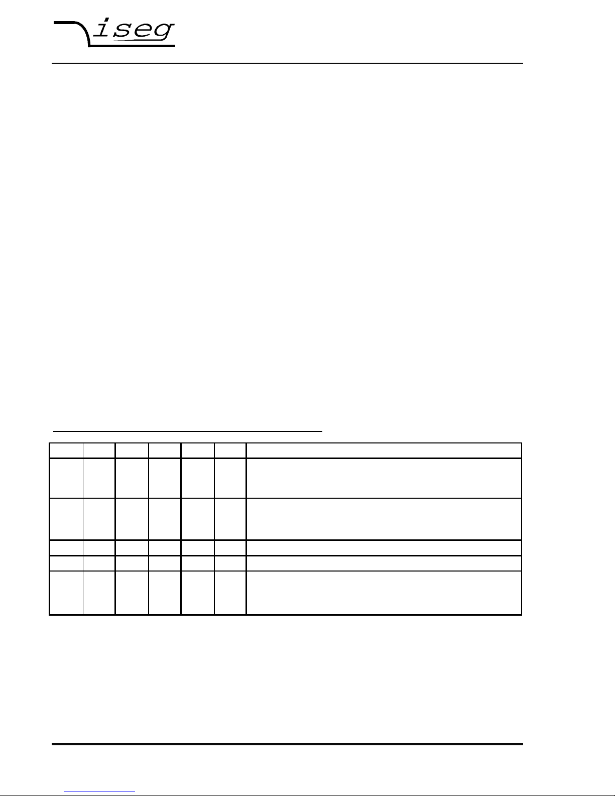
The data exchange between the controller and the Front-end (FE) device works with help of data
frames. These data frames are assembled of one direction bit DATA_DIR, one identifier bit
DATA_ID and further data bytes. The direction bit DATA_DIR defines whether the data frame is a
write or read-write access. The DATA_ID carries the information of the type of the data frame and
occasionally sub addresses (G0, G1). It is characterised through the first byte of the data frame with
bit 7=1. The function of the module as part of a complex system will be defined through the
DATA_ID .
In such systems with many hierarchical levels a single function of a single module can be addressed
by using group controllers (GC). Then, for each GC on the way to the module the data frame is
created through nesting of the address fields of the GC-addresses followed by the DATA_ID (not
necessary in case of control a single module).
EXT_
INSTR
DATA
_DIR
DATA_ID
Bit
Access
7 6 5 4 3 2 1 0
x
0
x x x x x x x
No DATA_ID
0/1
0
1 0 x x x x x x
Write access on Front-end device
0/1
1
1 0 x x x x x x
Read-write access on Front-end device
(Request at Write)
0/1
0
1 1 x x x x
G1 G0 Write access on group
0/1
1
1 1 x x x x
G1 G0 Read-write access on group (Request at Write)
G0, G1 sub address
Only needed if group controller (GC) is used
These data frames correspond to a transfer into layer 3 (Network Layer) respectively layer 4
(Transport Layer) of the OSI model of ISO. The transmission medium is CAN Bus according to
specification 2.0A, related to level1 (Physical Layer) and level 2 (Data Link Layer).
The Device Control Protocol DCP has been matched to the CAN Bus according to specification CAN
2.0A, but it is also possible to be matched to further transmission media (e.g. RS232). Therefore
specials of layer 1 and 2 are only mentioned if absolutely necessary and if misunderstandings of
functions between the Transport Layer and functions of the Data Link Layer may be possible. The
communication between the controller and a module on the same bus segment will be described as
follows.
Page 6
Spezialelektronik GmbH
iseg c/o ROTECH Email: sales@iseg-hv.de Phone ++ 49 351 / 26 95 - 260
Spezialelektronik Bautzner Landstr. 45 http://www.iseg-hv.com Fax ++ 49 351 / 26 95 - 261
6 GmbH D - 01454 Rossendorf Germany
4.2 Summary of CAN data frames
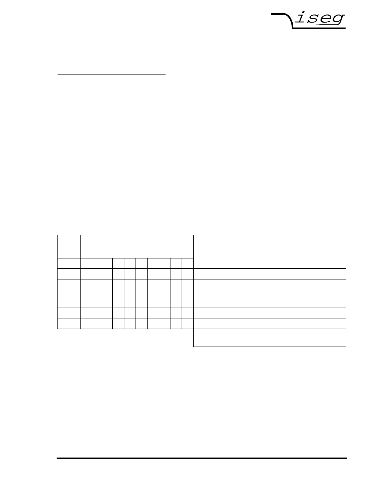
The 9-channel Module EHQ 9005-F is assembled of two sub-modules (8 channels / 1 channel),
each controlled independently via an own CAN identifier.
Following list describes the accesses of the DCP made for one of these sub-modules.
EXT_
INSTR
DATA_
DIR
DATA_ID
Bit
Access
read/
write/
active
DATA
-
Bytes
ID1 ID0 7 6 5 4 3 2 1 0
x
0
x x x x x x x
No DATA_ID
x x 1 0 C1 C0 N3 N2 N1 N0 Single access CHANNEL:
1 1/0 1 0 0 0 N3 N2 N1 N0 Current trip r/w 4
0 1 1 0 0 0 N3 N2 N1 N0 Actual voltage r 4
0 1 1 0 0 1 N3 N2 N1 N0 Actual current r 4
0 1/0 1 0 1 0 N3 N2 N1 N0 Set voltage r/w 4
0 1 1 0 1 1 N3 N2 N1 N0 Status channel r 3
1 1 C3 C2 C1 C0 G1 G0 Group access module
1 1 1 1 0 0 0 0 0 0 Voltage supplies and module temp. r 8
1 1 1 1 0 0 0 1 0 0 free r 8
1 1 1 1 0 0 1 0 0 0 Existing hardware channels r 3
1 1 1 1 0 0 1 1 0 0 Channel works according to control r 3
1 1 1 1 0 1 0 0 0 0
Status4 Sense voltage ≠ Set voltage
r 3
0 1/0 1 1 0 0 0 0 0 0 General status module r/wa2
0 1 1 1 0 0 0 1 0 0 Status1 Voltage limit has been
exceeded at single channel
r 3
0 1 1 1 0 0 1 0 0 0 Status2 Hardw. current limit has been
exceeded at single channel
r 3
0 1/0 1 1 0 0 1 1 0 0 Channel ON / OFF r/w 3
0 1/0 1 1 0 1 0 0 0 0 Ramp speed r/w 3
0 0 1 1 0 1 0 1 0 0 Emergency cut-off w 3
0 1 1 1 0 1 1 0 0 0 Log-on Front-end device in superior
layer
a 3
0 0 1 1 0 1 1 0 0 0 Log-off superior layer at Front-end
device
w 3
0 1/0 1 1 0 1 1 1 0 0 Bit rate r/w 3
0 1/0 1 1 1 0 0 0 0 0 Serial number, software release and
CAN message configuration
r/w 7/2
0 0 1 1 1 0 0 1 0 0 Set voltage for all channels w 4
0 1/0 1 1 1 0 1 1 0 0 KILL-enable r/w 3
0 1/0 1 1 1 1 0 0 0 0 ADC filter setting r/w 3
0 1 1 1 1 1 0 1 0 0 Module nominal values r 5
0 1 1 1 1 1 1 0 0 0 Status3 Software current trip has been
exceeded at single channel
r 3
Ci: Accesses Ni 0 to 15: Channel 0 to 15
Gi 0 to 3: Group 0 to 3 Only needed if group controller (GC) is used
Page 7
Spezialelektronik GmbH
iseg c/o ROTECH Email: sales@iseg-hv.de Phone ++ 49 351 / 26 95 - 260
Spezialelektronik Bautzner Landstr. 45 http://www.iseg-hv.com Fax ++ 49 351 / 26 95 - 261
GmbH D - 01454 Rossendorf Germany 7
4.3 Detailed CAN data frames description
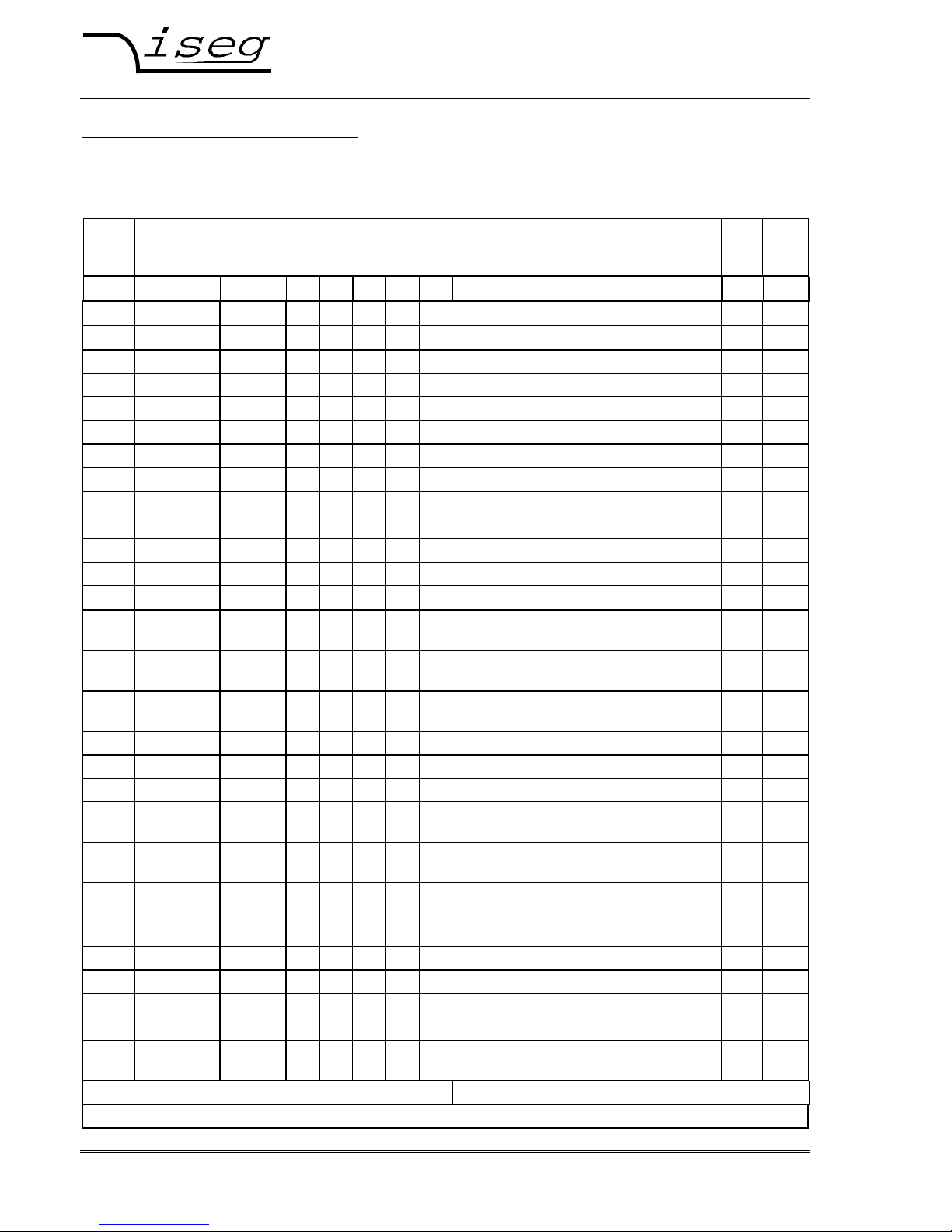
Log-on and Log-off Front-end (FE) device (active/write access)
Log-on frame 8-channel module (DLC = 3)
Byte DATA_ID DATA_1 DATA_0
Bit 7 6 5 4 3 2 1 0 7 5 4 3 2 1 0 7 1 0
Designation DATA
_DIR
G1 G0
Data 1 1 1 0 1 1 0 0 0 u v w x y z 1 0
Description active G1 to G0: Group 0 to 3
Only needed if group
controller (GC) is used
Values of bit z to u:
see Group access:
General status module
Type HIGH resolution
After POWER ON the module will give this group access cyclically on the bus (ca. 2...10 sec).
Bit 0 to 5 in DATA_1 describes the general status of the module (see Group access: General status
module). If a controller identifies this access then it is able to register this module as a Front-end device and is
able to address it with FE_ADR.
(Module address, see also item 4.4, description 11bit-Identifier)
Bit 0 to 1 in DATA_0 describes the type of installed resolution of current and voltage measurement and setting
(see according Single and Group accesses).
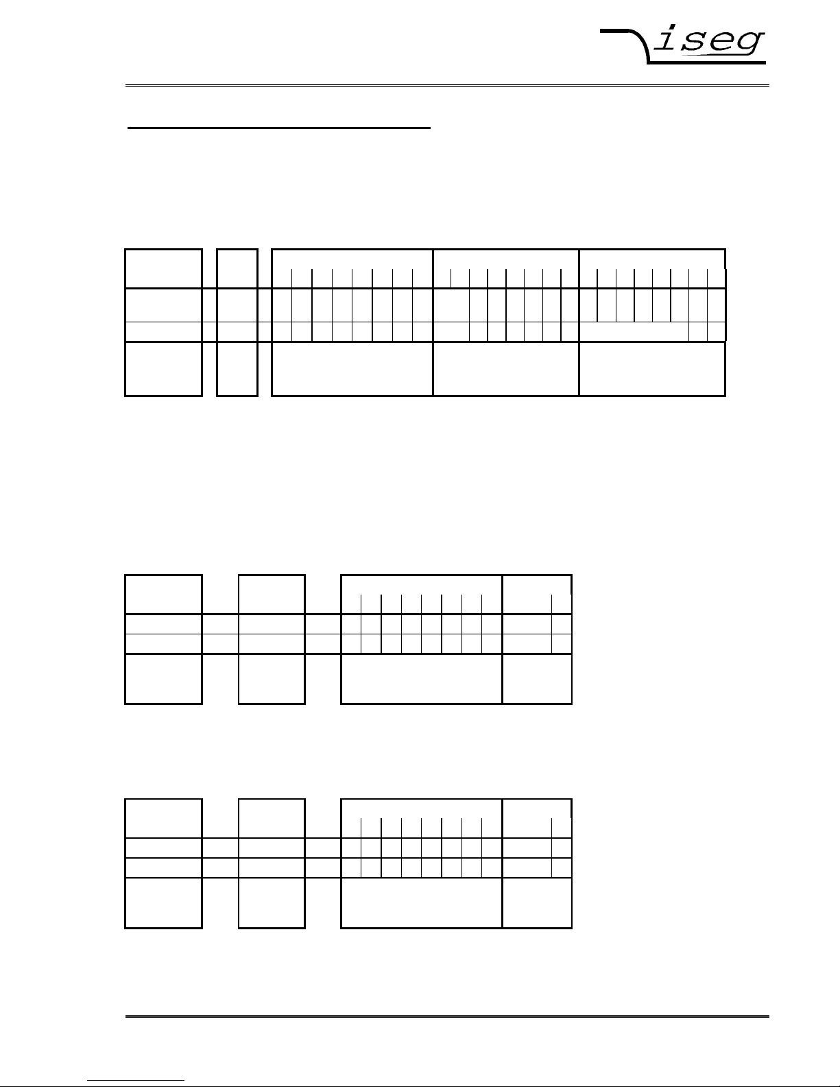
Remote-frame Log-on controller (DLC = 2)
Byte DATA_ID DATA_0
Bit 7 6 5 4 3 2 1 0 0
Designation DATA_DIR G1 G0
Data 0 1 1 0 1 1 0 0 0 1
Description write G1 to G0: Group 0 to 3
Only needed if group
controller (GC) is used
Module is
log-on
The module will not send further ‘Log-on controller” accesses after the successful registration as long as it
receives accesses from the external CAN Bus in periods shorter than one minute and until the controller will
send a ‘Log-off controller” access to the Front-end device, respectively.
Remote-frame Log-off controller (DLC = 2)
Byte DATA_ID DATA_0
Bit 7 6 5 4 3 2 1 0 0
Designation DATA_DIR G1 G0
Data 0 1 1 0 1 1 0 0 0 0
Description write G1 to G0: Group 0 to 3
Only needed if group
controller (GC) is used
Module is
log-off
Page 8

Spezialelektronik GmbH
iseg c/o ROTECH Email: sales@iseg-hv.de Phone ++ 49 351 / 26 95 - 260
Spezialelektronik Bautzner Landstr. 45 http://www.iseg-hv.com Fax ++ 49 351 / 26 95 - 261
8 GmbH D - 01454 Rossendorf Germany
Single access CHANNEL: Current trip (Read-write/Write access), extended access list
Read-write
Byte Identifier DATA_ID Controller (DLC = 1):
Bit ID1 ID0 7 6 5 4 3 2 1 0 Read actual software current trip
Designation EXT_
INSTR
DATA
_DIR
N3 N2 N1 N0
at the corresponding channel
Data 1 1 1 0 0 0 x x x x
Description read Channel Nx off 0 ... 15
⇓ Response module (DLC = 4)
Byte Identifier DATA_ID DATA_2 DATA_1 DATA_0
Bit ID1 ID0 7 6 5 4 3 2 1 0 0
Designation EXT_
INSTR
DATA
_DIR
N3 N2 N1 N0 LSB
Data 1 0 1 0 0 0 x x x x x
Description write Channel Nx off 0 ... 15 Actual current trip with resolution
I
O max
/ 10∗exp6 [A]
in DATA_2 to DATA_0
Write (Controller [DLC = 4]: Write software current trip at corresponding channel)
Byte Identifier DATA_ID DATA_2 DATA_1 DATA_0
Bit ID1 ID0 7 6 5 4 3 2 1 0 ... 0
Designation EXT_
INSTR
DATA
_DIR
N3 N2 N1 N0 LSB
Data 1 0 1 0 0 0 x x x x x
Description write Channel Nx off 0 ... 15 New actual current trip with resolution
I
O max
/ 10∗exp6 [A]
in DATA_2 to DATA_0
If the channel is in ‘ON’ and the measured output current will exceed the programmed current trip, then the
voltage will be shut off without ramp (Bit o = 0 in ‘Status channel’).
At the same time bit t in ‘Status channel’ and bit z in ‘ General status module’ will be set. These bits will be
reset if ‘Status3 Software current trip’ will be read.
With help of the ‘Group access’ ‘Switch ON /OFF’ the concerning channels are switched ON again.
Function will be switched off with write ‘Current trip = 0’.
Page 9

Spezialelektronik GmbH
iseg c/o ROTECH Email: sales@iseg-hv.de Phone ++ 49 351 / 26 95 - 260
Spezialelektronik Bautzner Landstr. 45 http://www.iseg-hv.com Fax ++ 49 351 / 26 95 - 261
GmbH D - 01454 Rossendorf Germany 9
Single access CHANNEL: Actual voltage (Read-write access)
Byte DATA_ID Controller (DLC = 1):
Bit 7 6 5 4 3 2 1 0 Read actual voltage at the corresponding channel
Designation DATA
_DIR
N3 N2 N1 N0
Data 1 1 0 0 0 x x x x
Description read Channel Nx of 0 ... 15
⇓ Response module (DLC = 4)
Byte DATA_ID DATA_2 DATA_1 DATA_0
Bit 7 6 5 4 3 2 1 0 0
Designation DATA
_DIR
N3 N2 N1 N0 LSB
Data 0 1 0 0 0 x x x x x
Description write Channel Nx of 0 ... 15
Actual voltage with resolution V
O max
/ 10∗exp6 [V]
in DATA_2 to DATA_0
Single access CHANNEL: Actual current (Read-write access)
Byte DATA_ID Controller (DLC = 1):
Bit 7 6 5 4 3 2 1 0 Read actual current at the corresponding channel
Designation DATA
_DIR
N3 N2 N1 N0
Data 1 1 0 0 1 x x x x
Description read Channel Nx of 0 ... 15
⇓ Response module (DLC = 4)
Byte DATA_ID DATA_2 DATA_1 DATA_0
Bit 7 6 5 4 3 2 1 0 0
Designation DATA
_DIR
N3 N2 N1 N0 LSB
Data 0 1 0 0 1 x x x x x
Description write Channel Nx of 0 ... 15
Actual current with resolution I
O max
/ 10∗exp6 [A]
in DATA_2 to DATA_0
Page 10

Spezialelektronik GmbH
iseg c/o ROTECH Email: sales@iseg-hv.de Phone ++ 49 351 / 26 95 - 260
Spezialelektronik Bautzner Landstr. 45 http://www.iseg-hv.com Fax ++ 49 351 / 26 95 - 261
10 GmbH D - 01454 Rossendorf Germany
Single access CHANNEL: Set voltage (Read-write/Write access)
Read-write
Byte DATA_ID Controller (DLC = 1):
Bit 7 6 5 4 3 2 1 0 Read set voltage at the corresponding channel
Designation DATA
_DIR
N3 N2 N1 N0
Data 1 1 0 1 0 x x x x
Description read Channel Nx of 0 ... 15
⇓ Response module (DLC = 4)
Byte DATA_ID DATA_2 DATA_1 DATA_0
Bit 7 6 5 4 3 2 1 0 0
Designation DATA
_DIR
N3 N2 N1 N0 LSB
Data 0 1 0 1 0 x x x x x
Description write Channel Nx of 0 ... 15
Set voltage with resolution V
O max
/ 10∗exp6 [V]
in DATA_2 to DATA_0
Write (Controller [DLC = 4]: Write set voltage at corresponding channel)
Byte DATA_ID DATA_2 DATA_1 DATA_0
Bit 7 6 5 4 3 2 1 0 0
Designation DATA
_DIR
N3 N2 N1 N0 LSB
Data 0 1 0 1 0 x x x x x
Description write Channel Nx of 0 ... 15
Set voltage with resolution V
O max
/ 10∗exp6 [V]
in DATA_2 to DATA_0
If the channel is switched ‘ON’ then the voltage will be ramped to the set value after the receipt of this access.
Otherwise the set value will just be stored and only used for ramping to the set voltage after the channel will be
switched ‘ON’.
Set voltages higher than the maximum module voltage will be ignored and the bit ‘Input error’ of the ‘Status
channel’ will be set.
Page 11

Spezialelektronik GmbH
iseg c/o ROTECH Email: sales@iseg-hv.de Phone ++ 49 351 / 26 95 - 260
Spezialelektronik Bautzner Landstr. 45 http://www.iseg-hv.com Fax ++ 49 351 / 26 95 - 261
GmbH D - 01454 Rossendorf Germany 11
Single access CHANNEL: Status channel (Read-write access)
Byte DATA_ID Controller (DLC = 1):
Bit 7 6 5 4 3 2 1 0 Read channel status at the corresponding channel
Designation DATA
_DIR
N3 N2 N1 N0
Data 1 1 0 1 1 x x x x
Description read Channel Nx of 0 ... 15
⇓ Response module (DLC = 3)
Byte DATA_ID DATA_1 DATA_0
Bit 7 6 5 4 3 2 1 0 7 6 5 4 3 2 1 0 7 ..2 1 0
Designation DATA
_DIR
N3 N2 N1 N0 v c k n r o i f s t
Data 0 1 0 1 1 x x x x x x x x x x x 0 x x
Description write Channel Nx of 0 ... 15 Input-error
i=0, no inputerror
i=1, set voltage,
fN or ramp out off
set range
o=0 ⇒ Channel OFF
o=1 ⇒ Channel ON
Voltage state
r=0 ⇒ Voltage is stable
r=1 ⇒ Voltage ramps
Channel Emergency cut-off
n=0 ⇒ Channel works
n=1 ⇒ Cut-off (only to first
write in DAC)
KILL-enable
k=0 ⇒KILL function disable:
VO shut off if current limit has
been exceeded and then VO is
ramping from 0V to V
SET
k=1 ⇒KILL function enable:
VO shut off permanently if
current limit has been
exceeded
Current limit
c=0 ⇒ Channel is ok
c=1⇒ VO shut of 0 V because hardware
current limit has been exceeded
Voltage limit
v=0 ⇒ Channel is ok
v=1 ⇒ VO shut of permanently because
voltage limit has been exceeded
Sense
s=0 Sense o.k.; s=1 Sense fault
Current trip
t=1 ⇒ VO shut of 0 V
because software current trip has been exceeded
Page 12

Spezialelektronik GmbH
iseg c/o ROTECH Email: sales@iseg-hv.de Phone ++ 49 351 / 26 95 - 260
Spezialelektronik Bautzner Landstr. 45 http://www.iseg-hv.com Fax ++ 49 351 / 26 95 - 261
12 GmbH D - 01454 Rossendorf Germany
Group access: Voltage supplies and module temperature (Read-write), extended access list
Read-write
Byte Identifier DATA_ID Controller (DLC = 1):
Bit ID1 ID0 7 6 5 4 3 2 1 0 Read voltage supplies and the
Designation EXT_
INSTR
DATA
_DIR
module temperature
Data 1 1 1 1 0 0 0 0 0 0
Description read
⇓ Response module (DLC = 8)
Byte Identifier DATA_ID DATA_n
Bit ID1 ID0 7 6 5 4 3 2 1 0 6 5 4 3 2 1 0
Designation EXT_
INSTR
DATA
_DIR
U1 U2 U3 U4 U5 t2 t1
Data 1 0 1 1 0 0 0 0 0 0 x x x 0 0 x x
Description write +24V +15V +5V 0 0 Temperature
U1 to U3: Voltage resolution 100 mV
U4; U5 not available on EHQ 8005-F
t2 & t1: Module temperature resolution 0,1 °C
Out of range (see Group access: General status module) will be generated if tolerance of voltage supplies is
more than ± 5%.
Group access : Existing hardware channels (Read-write/Write access), extended access list
Read-write
Byte Identifier DATA_ID Controller (DLC = 1):
Bit ID1 ID0 7 6 5 4 3 2 1 0 Read the existing hardware channels
Designation EXT_
INSTR
DATA
_DIR
at the corresponding module
Data 1 1 1 1 0 0 1 0 0 0
Description read
⇓ Response module (DLC = 3)
Byte Identifier DATA_ID DATA_1 DATA_0
Bit ID1 ID0 7 6 5 4 3 2 1 0 7 ... 0 7 ... 0
Designation EXT_
INSTR
DATA
_DIR
N3 N2 N1 N0 LSB
Data 1 0 1 1 0 0 1 0 0 0 x
Description write x=1: channel is existing
x=0: channel is not existing
LSB = channel 1
Page 13

Spezialelektronik GmbH
iseg c/o ROTECH Email: sales@iseg-hv.de Phone ++ 49 351 / 26 95 - 260
Spezialelektronik Bautzner Landstr. 45 http://www.iseg-hv.com Fax ++ 49 351 / 26 95 - 261
GmbH D - 01454 Rossendorf Germany 13
Group access : Channel works according to control (Read-write/Write access),
extended access list
Read-write
Byte Identifier DATA_ID Controller (DLC = 1):
Bit ID1 ID0 7 6 5 4 3 2 1 0 Are channels working correctly according to
Designation EXT_
INSTR
DATA
_DIR
control?
Data 1 1 1 1 0 0 1 1 0 0
Description read
⇓ Response module (DLC = 3)
Byte Identifier DATA_ID DATA_1 DATA_0
Bit ID1 ID0 7 6 5 4 3 2 1 0 7 ... 0 7 ... 0
Designation EXT_
INSTR
DATA
_DIR
N3 N2 N1 N0 LSB
Data 1 0 1 1 0 0 1 1 0 0 x
Description write x=1: Channel is working correctly
x=0: Channel is not working correctly
LSB = Channel 1
Group access : Status4 (Read-write/Write access), extended access list
Read-write
Byte Identifier DATA_ID Controller (DLC = 1):
Bit ID1 ID0 7 6 5 4 3 2 1 0 Control of sense line (is Vset = Vsense ?)
Designation EXT_
INSTR
DATA
_DIR
Data 1 1 1 1 0 1 0 0 0 0
Description read
⇓ Response module (DLC = 3)
Byte Identifier DATA_ID DATA_1 DATA_0
Bit ID1 ID0 7 6 5 4 3 2 1 0 7 ... 0 7 ... 0
Designation EXT_
INSTR
DATA
_DIR
N3 N2 N1 N0 LSB
Data 1 0 1 1 0 1 0 0 0 0 x
Description write
x=1: Vset ≠ Vsense (Sense error)
x=0: Vset = Vsense (± tolerance)
LSB = Channel 1
Page 14

Spezialelektronik GmbH
iseg c/o ROTECH Email: sales@iseg-hv.de Phone ++ 49 351 / 26 95 - 260
Spezialelektronik Bautzner Landstr. 45 http://www.iseg-hv.com Fax ++ 49 351 / 26 95 - 261
14 GmbH D - 01454 Rossendorf Germany
Group access: General status module (Read-write/Write/Active access)
Read-write
Byte DATA_ID Controller (DLC = 1):
Bit 7 6 5 4 3 2 1 0 Read status at the corresponding module
Designation DATA
_DIR
Data 1 1 1 0 0 0 0 0 0
Description read
⇓ Response module (DLC = 2)
Byte DATA_ID DATA_0
Bit 7 6 5 4 3 2 1 0 7 5 4 3 2 1 0
Designation DATA
_DIR
Data 0 1 1 0 0 0 0 0 0 u v w x y z
Description write z=1 ‘Status channel’ bit c & v & t & s = 0 for all channels:
no current limit/trips and no voltage limit have been
exceeded in the module, sense is okay
z=0 current limit/trips or voltage limit have been
exceeded or sense line interrupted at least one channel
y=1 no channel is ramping
y=0 VO is ramping at least one channel
x=1 safety loop is closed
x=0 VO was shut off with safety loop, if safety loop is closed
again the bit will be set with the first read
w=1 VO is ramping at least one channel
with ADC filter frequency fN = 100 Hz
w=0 all channels are stable with
programmable ADC filter frequency f
N
(ADC conversion time = 1 / fN , see
‘ADC filter frequency setting‘, ex works fN = 50 Hz)
v=1 averaging ON
v=0 averaging OFF
u=1 voltage supplies in range
u=0 voltage supplies out of range
Write (Controller [DLC = 2]: Write averaging ON / OFF)
Byte DATA_ID DATA_0
Bit 7 6 5 4 3 2 1 0 7 ... 4 ... 0
Designation DATA
_DIR
Data 0 1 1 0 0 0 0 0 0 masked v masked
Description write v=1 averaging ON
v=0 averaging OFF
If the averaging is ‘ON’ then the voltage and current measurement will work with a ‘Weighted Average
Calculation’ of 16 ADC measurement values.
Page 15

Spezialelektronik GmbH
iseg c/o ROTECH Email: sales@iseg-hv.de Phone ++ 49 351 / 26 95 - 260
Spezialelektronik Bautzner Landstr. 45 http://www.iseg-hv.com Fax ++ 49 351 / 26 95 - 261
GmbH D - 01454 Rossendorf Germany 15
Active (Module [DLC = 2]: Module sends total error active with high priority, response time < 150 ms)
Byte Identifier DATA_ID DATA_0
Bit 7 6 5 4 3 2 1 0 7 5 4 3 2 1 0
Designation ID9 DATA
_DIR
Data 0 1 1 1 0 0 0 0 0 0
u
v w
x
y
z
Description active If u & x & z = 0, then the module send once active this
error frame with ID9 = 0
The module has been configured as one CAN-node with an Active-CAN message function (see Group access:
Serial number, software release and CAN message configuration). In this case the module will send this
group access as an active error message with higher priority (ID9 = 0) than normal messages, only if one of the
sumstatus- and safety loop-bits in the group access “General status module” not has been set.
Page 16

Spezialelektronik GmbH
iseg c/o ROTECH Email: sales@iseg-hv.de Phone ++ 49 351 / 26 95 - 260
Spezialelektronik Bautzner Landstr. 45 http://www.iseg-hv.com Fax ++ 49 351 / 26 95 - 261
16 GmbH D - 01454 Rossendorf Germany
Group access: Status1 Voltage limit (Read-write access)
Byte DATA_ID Controller:
Bit 7 6 5 4 3 2 1 0 Check exceeding voltage limit per channel
Designation DATA
_DIR
Data 1 1 1 0 0 0 1 0 0
Description read
⇓ Response module (DLC = 3)
Byte DATA_ID DATA_1 DATA_0
Bit 7 6 5 4 3 2 1 0 7 ... 0 7 ... 0
Designation DATA
_DIR
Data 0 1 1 0 0 0 1 0 0 x15 ... x8 x7 ... x0
Description write
x0 ⇒ Status for Channel 0 xn = 0 ⇒ Channel ok
:
x7 ⇒ Status for Channel 7 xn = 1 ⇒ Voltage limit has
been exceeded
If an external over voltage occurs at the channel output (i.e. Output voltage > Set voltage) then the channel will
be switched off and the according bit will be set. Only after the read of ‘Status 1 voltage limit’ this bit will be
cancelled.
Group access: Status2 Hardware current limit (Read-write access)
Byte DATA_ID Controller (DLC = 1):
Bit 7 6 5 4 3 2 1 0 Check exceeding hardware current limit per channel
Designation DATA
_DIR
Data 1 1 1 0 0 1 0 0 0
Description read
⇓ Response module (DLC = 3)
Byte DATA_ID DATA_1 DATA_0
Bit 7 6 5 4 3 2 1 0 7 ... 0 7 ... 0
Designation DATA
_DIR
Data 0 1 1 0 0 1 0 0 0 x15 ... x8 x7 ... x0
Description write
x0 ⇒ Status for Channel 0 xn = 0 ⇒ Channel ok
:
x7 ⇒ Status for Channel 7 xn = 1 ⇒ Hardware
current limit has been
exceeded.
The module responds to the exceeding of the hardware current limit which has been set in the channel in
dependence to the according KILL-enable bit (see also Group access ‘KILL-enable’) as follows:
KILL-enable = 1: Voltage will be switched off permanently without ramp, green LED on front panel is off.
KILL-enable = 0: Voltage will be switched off without ramp, green LED on front panel is off. If the output
voltage arrives at 0 V ramping to set voltage will be started automatically again.
The green LED flashes on again only after the Group access ‘Status2 Current limit’ has
been read.
Page 17

Spezialelektronik GmbH
iseg c/o ROTECH Email: sales@iseg-hv.de Phone ++ 49 351 / 26 95 - 260
Spezialelektronik Bautzner Landstr. 45 http://www.iseg-hv.com Fax ++ 49 351 / 26 95 - 261
GmbH D - 01454 Rossendorf Germany 17
Group access: Channel ON / OFF (Read-write /Write access)
Read-write
Byte DATA_ID Controller (DLC = 1):
Bit 7 6 5 4 3 2 1 0 Check Channels ON or OFF
Designation DATA
_DIR
Data 1 1 1 0 0 1 1 0 0
Description read
⇓ Response module (DLC = 3)
Byte DATA_ID DATA_1 DATA_0
Bit 7 6 5 4 3 2 1 0 7 ... 0 7 0
Designation DATA
_DIR
Data 0 1 1 0 0 1 1 0 0 x15 ... x8 x7 ... x0
Description write
x0 ⇒ Bit for Channel 0 xn = 1 ⇒ Channel ON
:
x7 ⇒ Bit for Channel 7 xn = 0 ⇒ Channel OFF
Write (Controller [DLC = 3]: Channels shut ON or OFF define)
Byte DATA_ID DATA_1 DATA_0
Bit 7 6 5 4 3 2 1 0 7 ... 0 7 ... 0
Designation DATA
_DIR
Data 0 1 1 0 0 1 1 0 0 x15 x8 x7 x0
Description write
x0 ⇒ Bit for Channel 0 xn = 1 ⇒ Channel ON
:
x7 ⇒ Bit for Channel 7 xn = 0 ⇒ Channel OFF
Group access: Emergency cut-off (Write access)
Controller (DLC = 3): Channels ‘Emergency cut-off’
Byte DATA_ID DATA_1 DATA_0
Bit 7 6 5 4 3 2 1 0 7 ... 0 7 ... 0
Designation DATA
_DIR
Data 0 1 1 0 1 0 1 0 0 x15 x8 x7 x0
Description write x7 ... x0: for xn = 1: Channel 7 ... Channel 0
Channels cut-off without ramp
Page 18

Spezialelektronik GmbH
iseg c/o ROTECH Email: sales@iseg-hv.de Phone ++ 49 351 / 26 95 - 260
Spezialelektronik Bautzner Landstr. 45 http://www.iseg-hv.com Fax ++ 49 351 / 26 95 - 261
18 GmbH D - 01454 Rossendorf Germany
Group access: Ramp speed (Read-write /Write access)
Read-write
Byte DATA_ID Controller (DLC = 1):
Bit 7 6 5 4 3 2 1 0 Read actual ramp speed of module
Designation DATA
_DIR
Data 1 1 1 0 1 0 0 0 0
Description read
⇓ Response module (DLC = 3)
Byte DATA_ID DATA_1 DATA_0
Bit 7 6 5 4 3 2 1 0 7 ... 0 7 0
Designation DATA
_DIR
Data 0 1 1 0 1 0 0 0 0 ... x8 x7 ... x0
Description write x8 ... x0:
Ramp speed of module with resolution V
O max
/ 50000s
Write (Controller [DLC = 3]: Write ramp speed module)
Byte DATA_ID DATA_1 DATA_0
Bit 7 6 5 4 3 2 1 0 7 ... 0 7 0
Designation DATA
_DIR
Data 0 1 1 0 1 0 0 0 0 ... x8 x7 ... x0
Description write x8 ... x0:
Ramp speed of module with resolution V
O max
/ 50000s
Ramp speed range:
V
O max
/ 2500s ≤ Ramp speed ≤ V
O max
/ 10s )
1
Ramp speed higher than the maximum module specific
ramp speed will be ignored and the Bit ‘ Input error’ in the
‘Status channel’ will be set.
)1 : sub values are rounded down to the next lower value, according to the resolution.
Group access: Set voltage for all channels (Write access)
Controller (DLC = 4): Set voltage for all channels
Byte DATA_ID DATA_2 / DATA_1 DATA_0
Bit 7 6 5 4 3 2 1 0 7 ... 0 7 ... 0
Designation DATA
_DIR
LSB
Data 0 1 1 1 0 0 1 0 0
Description write Set voltage for all channels with resolution
V
O max
/ 10∗exp6 [V] in DATA_2 to DATA_0
If any channel is ‘ON’ then the voltage of which will be ramped on set voltage after the receipt of this write
access.
If any channel is ‘OFF’ then the set voltage of which will be stored in the module and after the channel will be
switched ‘ON’ ramping will be started up to the set voltage.
Set voltages higher than the maximum specific module voltage are ignored and the bit ‘Input Error’ in ‘Status
channel’ will be set.
Page 19

Spezialelektronik GmbH
iseg c/o ROTECH Email: sales@iseg-hv.de Phone ++ 49 351 / 26 95 - 260
Spezialelektronik Bautzner Landstr. 45 http://www.iseg-hv.com Fax ++ 49 351 / 26 95 - 261
GmbH D - 01454 Rossendorf Germany 19
Group access: Bit rate (Read-write/Write access)
Read-write
Byte DATA_ID Controller (DLC = 1):
Bit 7 6 5 4 3 2 1 0 Read actual bit rate
Designation DATA
_DIR
Data 1 1 1 0 1 1 1 0 0
Description read
⇓ Response module (DLC = 3)
Byte DATA_ID DATA_1 DATA_0
Bit 7 6 5 4 3 2 1 0 7 ... 0 7 0
Designation DATA
_DIR
Data 0 1 1 0 1 1 1 0 0 ... x8 x7 ... x0
Description write x8 ... x0: actual bit rate [kbit/s]
Write (Controller [DLC = 3]: Write a new bit rate)
Byte DATA_ID DATA_1 DATA_0
Bit 7 6 5 4 3 2 1 0 7 6 5 4 3 2 1 0 7 6 5 4 3 2 1 0
Designation DATA
_DIR
LSB
Data 0 1 1 0 1 1 1 0 0 x8 x7 x6 x5 x4 x3 x2 x1 x0
Description write x8 ... x0: - 7 Bit rates are possible:
1) 20 kbit/s
2) 50 kbit/s
3) 100 kbit/s
4) 125 kbit/s
5) 250 kbit/s
6) (500 kbit/s on request)
7) (1000 kbit/s on request)
- the new bit rate gets active after RESET
respectively POWER OFF/ON
and
- it has to be sure that the bit rate of all modules
in the system must be the same before a
RESET or POWER/ON is made.
- bit rate is prefixed from factory signed on a
sticker of the 96 pin connector.
- invalid bit rates will be ignored from the module
and the bit ‘Input error’ of the ‘Status channel 0’
will be set.
Page 20

Spezialelektronik GmbH
iseg c/o ROTECH Email: sales@iseg-hv.de Phone ++ 49 351 / 26 95 - 260
Spezialelektronik Bautzner Landstr. 45 http://www.iseg-hv.com Fax ++ 49 351 / 26 95 - 261
20 GmbH D - 01454 Rossendorf Germany
Group access: Serial number, software release and CAN message configuration
(Read-write/ Write access)
Read-write
Byte DATA_ID Controller (DLC = 1):
Bit 7 6 5 4 3 2 1 0 Read serial number and software release module
Designation DATA
_DIR
Data 1 1 1 1 0 0 0 0 0
Description read
⇓ Response module (DLC = 7)
Byte DATA_ID DATA_5 DATA_4 DATA_3 DATA_2 DATA_1 DATA_0
Bit 7 6 5 4 3 2 1 0 BCD BCD BCD BCD BCD BCD BCD BCD BCD BCD BCD BCD
Designation DATA
_DIR
Data 0 1 1 1 0 0 0 0 0 z6 z5 z4 z3 z2 z1 p2 y3 y2 y1 p1 c1
Description write 6 BCD Serial number 3 BCD Soft-
ware release
c1: 1 BCD existing channels
Write (Controller [DLC = 2]: Write a new CAN message configuration)
Byte DATA_ID DATA_0
Bit 7 6 5 4 3 2 1 0 BCD BCD
Designation DATA
_DIR
Data 0 1 1 1 0 0 0 0 0 0 x
Description write x = 2: with iseg Standard-CAN message
ID9 is always dominant
x = 4: with iseg Active-CAN message
ID9 is recessive
Page 21

Spezialelektronik GmbH
iseg c/o ROTECH Email: sales@iseg-hv.de Phone ++ 49 351 / 26 95 - 260
Spezialelektronik Bautzner Landstr. 45 http://www.iseg-hv.com Fax ++ 49 351 / 26 95 - 261
GmbH D - 01454 Rossendorf Germany 21
Group access: ADC filter frequency setting (Read-write/Write access)
(Programmable ADC conversion time = 1 / fN , fN ... filter first notch frequency)
Read-write
Byte DATA_ID Controller (DLC = 1):
Bit 7 6 5 4 3 2 1 0 Read actual ADC filter frequency f
N
Designation DATA
_DIR
- If all channels are stable then this ADC filter frequency f
N
is active
Data 1 1 1 1 1 0 0 0 0 - If VO is ramping at least one channel then the ADC filter
Description read
frequency is fN = 100 Hz
⇓ Response module (DLC = 3)
Byte DATA_ID DATA_1 DATA_0
Bit 7 6 5 4 3 2 1 0 7 ... 0 7 0
Designation DATA
_DIR
Data 0 1 1 1 1 0 0 0 0 x15 x8 x7 ... x0
Description write ADC filter frequency fN = 19200 / (x15 ... x0) [Hz]
Write (Controller [DLC = 3]: Write new ADC filter frequency f
N
)
Byte DATA_ID DATA_1 DATA_0
Bit 7 6 5 4 3 2 1 0 7 0 7 6 5 4 3 2 1 0
Designation DATA
_DIR
LSB
Data 0 1 1 1 1 0 0 0 0 x15 x8 x7 x0
Description write (x15 ... x0) = 19200 / ADC filter frequency fN [Hz]
with 5 Hz ≤ fN ≤ 100 Hz (invalid fN will be ignored and the bit
‘Input-error’ in ‘Status channel’ is set).
- if all channels arrive at V
set
the first time, further
measurements are made with this filter frequency. I.e.:
V
set
will be compared to V
actual
averaging according to f
N
- factory setting: fN = 50 Hz
Page 22

Spezialelektronik GmbH
iseg c/o ROTECH Email: sales@iseg-hv.de Phone ++ 49 351 / 26 95 - 260
Spezialelektronik Bautzner Landstr. 45 http://www.iseg-hv.com Fax ++ 49 351 / 26 95 - 261
22 GmbH D - 01454 Rossendorf Germany
Group access: KILL-enable (Read-write /Write access)
Read-write
Byte DATA_ID Controller (DLC = 1):
Bit 7 6 5 4 3 2 1 0 Read setting KILL function
Designation DATA
_DIR
KILL - enable: VO shut off permanently
if hardware current limit has been exceeded
Data 1 1 1 1 0 1 1 0 0
KILL - disable: VO shut off if current limit has been exceeded
Description read
and then VO is ramping from 0 V to V
SET
again
⇓ Response module (DLC = 3)
Byte DATA_ID DATA_1 DATA_0
Bit 7 6 5 4 3 2 1 0 7 ... 0 7 0
Designation DATA
_DIR
Data 0 1 1 1 0 1 1 0 0 x15 ... x8 x7 ... x0
Description write
x0 ⇒ Bit for Channel 0 xn = 1 ⇒ KILL - enable
:
x7 ⇒ Bit for Channel 7 xn = 0 ⇒ KILL - disable
Write (Controller [DLC = 3]: Set KILL function)
Byte DATA_ID DATA_1 DATA_0
Bit 7 6 5 4 3 2 1 0 7 ... 0 7 ... 0
Designation DATA
_DIR
Data 0 1 1 1 0 1 1 0 0 x15 x8 x7 x0
Description write
x0 ⇒ Bit for Channel 0 xn = 1 ⇒ KILL - enable
:
x7 ⇒ Bit for Channel 7 xn = 0 ⇒ KILL - disable
Page 23

Spezialelektronik GmbH
iseg c/o ROTECH Email: sales@iseg-hv.de Phone ++ 49 351 / 26 95 - 260
Spezialelektronik Bautzner Landstr. 45 http://www.iseg-hv.com Fax ++ 49 351 / 26 95 - 261
GmbH D - 01454 Rossendorf Germany 23
Group access: Module nominal values (Read-write access)
Byte DATA_ID Controller (DLC = 1):
Bit 7 6 5 4 3 2 1 0 Read Voltage and Current nominal values of the module
Designation DATA
_DIR
Data 1 1 1 1 1 0 1 0 0
Description read
⇓ Response module (DLC = 5)
Byte DATA_ID DATA_3 DATA_2 DATA_1 DATA_0
Bit 7 6 5 4 3 2 1 0 7 ... 0 7 ... 0 7 ... 0 7 ... 0
Designation DATA
_DIR
Data 0 1 1 1 1 0 1 0 0 x ... x x ... x x ... x x ... x
Description write Mantissa
V
max
Exponent
V
max
Mantissa
I
max
Exponent
I
max
Group access: Status3 Current limit (Read-write access)
Byte DATA_ID Controller (DLC = 1):
Bit 7 6 5 4 3 2 1 0 Check if the output current the software current trip per
Designation DATA
_DIR
channel exceeds
Data 1 1 1 1 1 1 0 0 0
Description read
⇓ Response module (DLC = 3)
Byte DATA_ID DATA_1 DATA_0
Bit 7 6 5 4 3 2 1 0 7 ... 0 7 ... 0
Designation DATA
_DIR
Data 0 1 1 1 1 1 0 0 0 x15 ... x8 x7 ... x0
Description write
x0 ⇒ Status for Channel 0 xn = 0 ⇒ Channel ok
:
x7 ⇒ Status for Channel 7 xn = 1 ⇒ Output current
has been exceeding the
programmable current trip.
If the measured output current exceeds the programmed current trip then the corresponding bits will be set.
The output voltage is not present and the channel is ‘OFF’ (Bit o = 0 in ‘Status channel’). A programmed
current limit with value zero has no effect to the current flow.
The setting bits in DATA_1 and DATA_0, the bit t in ‘Status channel’ and the bit z in ‘General status module’
will be reset after this access.
With help of the ‘Group access’ ‘Switch ON /OFF’ the concerning channels are switched ‘ON’ again.
Page 24

Spezialelektronik GmbH
iseg c/o ROTECH Email: sales@iseg-hv.de Phone ++ 49 351 / 26 95 - 260
Spezialelektronik Bautzner Landstr. 45 http://www.iseg-hv.com Fax ++ 49 351 / 26 95 - 261
24 GmbH D - 01454 Rossendorf Germany
4.4 Implementation in the CAN-Bus
The data frame structure is matched to the message frame of the standard-format according to CAN
specification 2.0A, whereas looking from the point of view of the CAN protocol a pure data
transmission will be done, which is not applying to the protocol.
The data frame of the DCP will be transferred as data-word with n bytes length in the data field of
the CAN frames according to the specific demands of the respective access. Therefore this results
into a Data Length Code (DLC) of the CAN-protocol of n.
It is possible to transfer 8 data bytes that apply to the DLC field with falling values.
The RTR Bit is always set to zero.
The information for the direction of the data transfer (DATA_DIR) is written in the lowest bit ID0 of
the 11 Bit CAN-Identifier.
The controller therefore will start a read-write access for data with DATA_DIR = 1 and will send with
DATA_DIR = 0.
The Front-end device responds to the data request with sending the corresponding data with
DATA_DIR = 0.
Only if the Front-end device is not registered at the controller respectively if it does not receive valid
data during a longer time period (ca. 1 min), then it will actively send the registration frame with
DATA_DIR = 1 (see also item 4.3)
Therefore it follows that all even CAN-ports (Identifier) are interpreted as ‘Write ports’ all odd CAN
ports as ‘ Read ports’.
The addressing of the Front-end device is also made with the 11 bit identifier of the CAN protocol.
In order to keep the CAN segment open also for other protocols, the addressing room was limited to
64 nodes.
ID10 is dominant.
ID9 - is always dominant for module’s witches have not an Active-CAN message function.
- is recessive for module’s witch have an Active-CAN message function when receive or
send write- or read- write-accesses and is dominant when the module active send a
error message.
The module was configured as a CAN-node with an Active-CAN message function (see Group
access: Serial number, software release and CAN message configuration). In this case the
module will send this group access as an active error message with higher priority (ID9 = 0)
than normal messages, if one of the sumstatus- and safety loop-bits in the group access
“General status module” not has been set.
ID3 to ID8 allows to address up to 64 Front-end devices (ID3: A0 = 20 ;...; ID8: A5 = 25 ),
ID2 is not used.
In one CAN segment only modules are allowed with different identifiers and the same bit rates.
The factory fixed bit rate is written on the sticker of the 96-pin connector.
Page 25

Spezialelektronik GmbH
iseg c/o ROTECH Email: sales@iseg-hv.de Phone ++ 49 351 / 26 95 - 260
Spezialelektronik Bautzner Landstr. 45 http://www.iseg-hv.com Fax ++ 49 351 / 26 95 - 261
GmbH D - 01454 Rossendorf Germany 25
Following data frame is valid for the control of the Front-end device in this lowest CAN segment.
S Identifier R DLC n – data bytes CRC ack
O T 0 0
(n = 1 - 8) DATA_ID
DATA_(n-2) ≥ 0 DATA_(n-3) ≥ 0
DATA_ ...
F.
F
b10 b0
R
Reserv
b3 b0 b7=1 b0 b7 b0 b7 b0 b7 b0 15 bit
ID10 ID9 ID8 ID7 ID6 ID5 ID4 ID3 ID2 ID1 ID0
0 P A5 A4 A3 A2 A1 A0 EXT
_IN
STR
DATA
_DIR
Acceptance-Filter of the used CAN-Controller is
set to Front-end-address
The Front-end device must do:
- Processing of the single accesses with direct channel values.
- Processing of group information of the channels.
- Self-registration in the higher level through sending the module address.
- Building of status information.
- Sending an active error message with higher priority if one of the sumstatus- and safety loop -bits
in the group access “General status module” has not been set (the module must be configured as
a CAN-node with an Active-CAN message function).
Page 26

Spezialelektronik GmbH
iseg c/o ROTECH Email: sales@iseg-hv.de Phone ++ 49 351 / 26 95 - 260
Spezialelektronik Bautzner Landstr. 45 http://www.iseg-hv.com Fax ++ 49 351 / 26 95 - 261
26 GmbH D - 01454 Rossendorf Germany
Appendix A: Side view
Desk open, jumper for safety-loop
 Loading...