

Page 1
Spezialelektronik GmbH
iseg Spezialelektronik GmbH Email: sales@iseg-hv.de Phone ++ 49 351 / 26 996 - 0
Bautzner Landstr. 23 http://www.iseg-hv.com Fax ++ 49 351 / 26 996 - 21
D - 01454 Radeberg / Rossendorf Germany
Precision High Voltage Sources in 3U Eurocard Format
Operators Manual
Contents:
1. General information
2. Technical Data
3. NHQ Description
4. Front panel
5. Handling
6. RS232 Interface
7. Program example
Appendix A: Block diagram
Appendix B: Rotary switch locations
Attention!
-The unit shall not be operated with the cover removed.
-We decline all responsibility for damages and injuries caused by an improper use of the module. It is highly recommended to read the operators manual before any kind of operation.
Note
The information in this manual is subject to change without notice. We take no responsibility whatsoever for any
error in the document. We reserve the right to make changes in the product design without reservation and
without notification to the users.
Filename EHQ10x_eng.___; Version 2.04 from 26.02.98
Page 2

Spezialelektronik GmbH
iseg Spezialelektronik GmbH Email: sales@iseg-hv.de Phone ++ 49 351 / 26 996 - 0
Bautzner Landstr. 23 http://www.iseg-hv.com Fax ++ 49 351 / 26 996 - 21
D - 01454 Radeberg / Rossendorf Germany 2
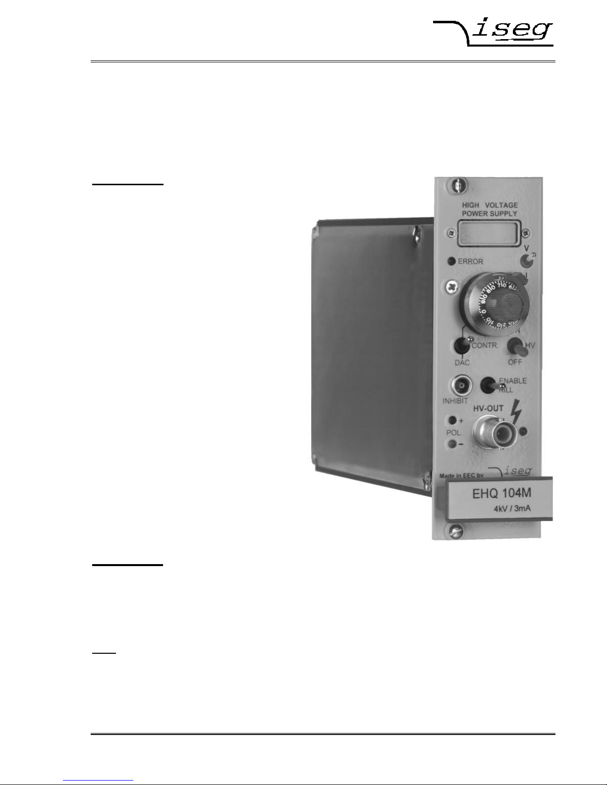
1. General information
The EHQ´s are one channel high voltage supplies in a 3U Eurocard Chassis, 8TE wide. The units offers manual
control and operation via RS232 interface (option: CAN Bus interface instead RS232). The use of the interface
supports more then the manual control functionality.
The high voltage supplies special provide high precision output voltage together with very low ripple and noise,
even under full load. Separate 10%-steps hardware switches put voltage and current limits. An INHIBIT input
protects connected sensitive devices. Additionally, the maximal output current is programmable via the interface.
The high voltage output protected against overload and short circuit. The output polarity can be switched over.
2. Technical data
Type (with RS 232) EHQ 102M EHQ 103M EHQ 104M EHQ 105M
Output voltage V
O
0 ... 2 kV 0 ... 3 kV 0 ... 4 kV 0 ... 5 kV
Output current I
O 24
0 ... 6 mA 0 ... 4 mA 0 ... 3 mA 0 ... 2 mA
Ripple and noise < 2 mV
P-P
< 5 mV
P-P
Resolution of current measurement
1 µA; Option 0n1: I
O max
= 100 µA ⇒ 100 nA
Resolution of voltage measurement 1 V
Accuracy current measurement ± (0,05% IO + 0,02% I
O max
+ 1 digit) for one year
voltage measurement ± (0,05% VO + 0,02% V
O max
+ 1 digit) for one year
LCD display 4 digits with sign, switch controlled
- voltage display in [V]
- current display in [µA]
Stability
∆ VO (no load / load) < 5 ∗ 10
-5
∆ VO/V
INPUT
< 5 ∗ 10
-5
Temperature coefficient
< 5 ∗ 10-5/K
Voltage control CONTROL switch in position
-manual: 10-turn potentiometer,
-DAC: control via serial interface
Rate of change of HV -ON/OFF 500 V/s (hardware ramp)
output voltage remote control 2 ... 255 V/s (software ramp)
Protection -separate current and voltage limit
(hardware, rotary switch in10%-steps)
-INHIBIT (external signal, TTL level, Low=active)
-programmable current limit (software)
Power requirement V
INPUT
± 24 V (< 500 mA), Option: ± 12 V ⇒ I
O 12
= I
O 24
/2
Operating temperature 0 . . . 50 °C
Storage temperature -20 . . . +60 °C
Packing 3U Euro cassette / 160 mm depth / 40,8 mm wide
Connector 96-pin connector according to DIN 41612
HV connector SHV-Connector at the front panel
Inhibit connector 1-pin Lemo-hub
Page 3

Spezialelektronik GmbH
iseg Spezialelektronik GmbH Email: sales@iseg-hv.de Phone ++ 49 351 / 26 996 - 0
Bautzner Landstr. 23 http://www.iseg-hv.com Fax ++ 49 351 / 26 996 - 21
D - 01454 Radeberg / Rossendorf Germany 3
3. EHQ Description
The function is described at a block diagram of the EHQ. This can be found in Appendix A.
High voltage supply
A patented high efficiency resonance converter circuit, which provides a low harmonic sine voltage on the HVtransformer, is used to generate the high voltage. The high voltage is rectified using a high speed HV-rectifier,
and the polarity is selected via a high-voltage switch. A consecutive active HV-filter damps the residual ripple and
ensures low ripple and noise values as well as the stability of the output voltage. A precision voltage divider is
integrated into the HV-filter to provide the set value of the output voltage, an additional voltage divider supplies the
measuring signal for the maximum voltage control. A precision measuring and AGC amplifier compares the actual
output voltage with the set value given by the DAC (computer control) or the potentiometer (manual control).
Signals for the control of the resonance converter and the stabilizer circuit are derived from the result of the
comparison. The two-stage layout of the control circuit results in an output voltage, stabilized with very high
precision to the set point.
Separate security circuits prevent exceeding the front-panel switch settings for the current I
max
and voltage V
max
limits. A monitoring circuit prevents malfunction caused by low supply voltage.
The internal error detection logic evaluates the corresponding error signals and the external INHIBIT signal. It
allows the detection of short overcurrent due to single flashovers in addition.
Digital control unit
A micro controller handles the internal control, evaluation and calibration functions of both channels. The actual
voltages and currents are read cyclically by an ADC with connected multiplexer and processed for display on the
4 digit LCD display. The current and voltage hardware limits are retrieved cyclically several times per second. The
reference voltage source provides a precise voltage reference for the ADC and generation of the control signals
in the manual operation mode of the unit.
The set values for the corresponding channels are generated by a 16-Bit DAC in computer controlled mode.
Filter
A special property of the unit is a tuned filtering concept, which prevents radiation of electromagnetic interference
into the unit, as well as the emittance of interference by the module. A filtering network is located next to the
connectors for the supply voltage and the converter circuits of the individual devices are also protected by filters.
The high-voltage filters are housed in individual metal enclosures to shield even minimum interference radiation.
Page 4
Spezialelektronik GmbH
iseg Spezialelektronik GmbH Email: sales@iseg-hv.de Phone ++ 49 351 / 26 996 - 0
Bautzner Landstr. 23 http://www.iseg-hv.com Fax ++ 49 351 / 26 996 - 21
D - 01454 Radeberg / Rossendorf Germany 4
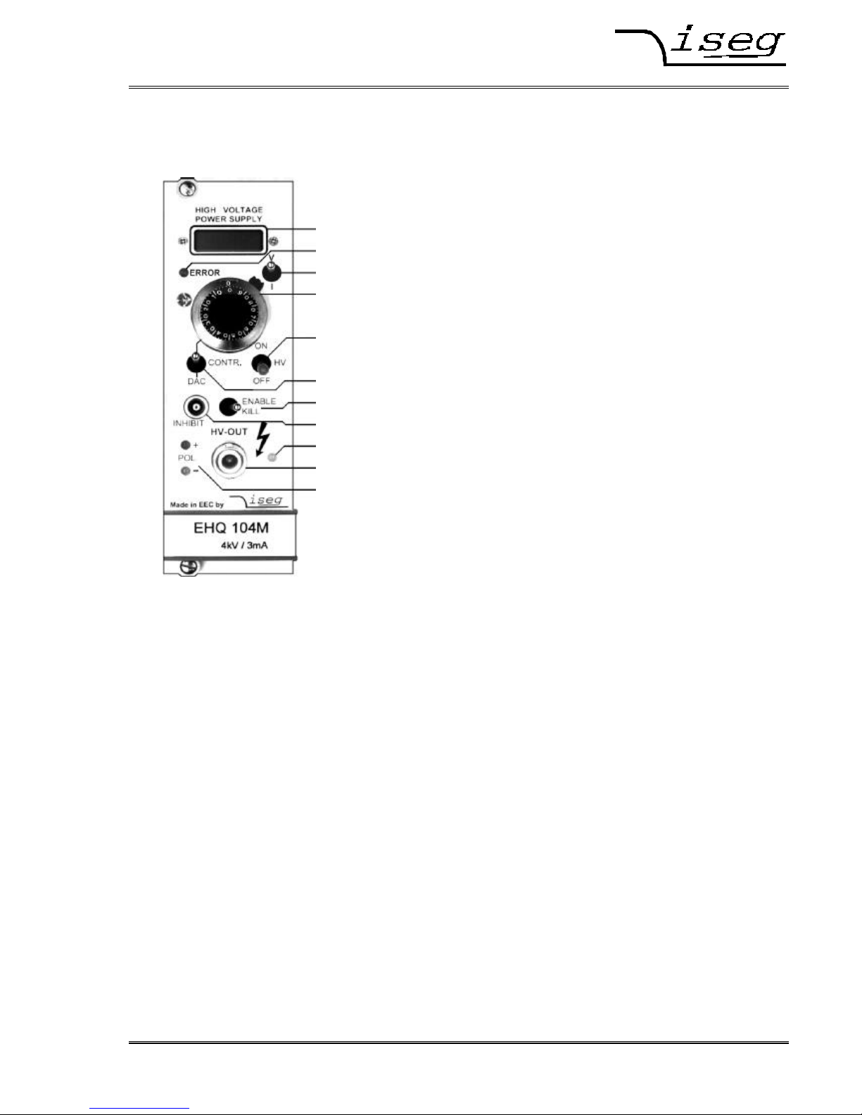
4. Front panel
[1] 4 digit LCD display
[2] Error indicator
[3] Measuring switch
[4] 10-turn potentiometer
[5] HV-ON switch
[6] CONTROL switch
[7] KILL switch
[8] INHIBIT input
[9] HV-ON indicator
[10] HV output
[11] Polarity indicator
5. Handling
The state of readiness of the unit is produced at the 96-pin connector according to DIN 41612 on the flipside.
The Output polarity is selectable with help of a rotary switch on the cover side (see appendix B). The chosen
polarity is displayed by a LED on the front panel [11] and a sign on the LCD display [1].
Attention! It is not allowed to change the polarity under power!
An undefined switch setting (not at one of the end positions) will cause no output voltage.
High voltage output is switched on with HV-ON switch [5] at the front panel. The viability is signalled by the yellow
LED [9].
Attention! If the CONTROL switch [6] is in upper position (manual control), high voltage is generated
at HV-output [10] with a ramp speed from 500 V/s (hardware ramp) to the set voltage
chosen via 10-turn potentiometer [4].
This is also the case, if RS232 control is switched over to manual control while operating.
If the CONTROL switch [6] is in lower position (DAC), high voltage will be activated only after receiving
corresponding RS232 commands.
Attention!
If at the last working of the unit activated the function ″Autostart″, the high voltage will be
generated with the saved parameters immediately!
Page 5

Spezialelektronik GmbH
iseg Spezialelektronik GmbH Email: sales@iseg-hv.de Phone ++ 49 351 / 26 996 - 0
Bautzner Landstr. 23 http://www.iseg-hv.com Fax ++ 49 351 / 26 996 - 21
D - 01454 Radeberg / Rossendorf Germany 5
On the LCD [1] output voltage in [V] or output current in [µA] will be displayed depending on the position of the
Measuring switch [3].
If working with manual control, output voltage can be set via 10-turn potentiometer [4] in a range from 0 to the set
maximal voltage.
If the CONTROL switch [6] is switched over to RS232 control, the DAC takes over the last set output voltage of
manual control. Output voltage can be generated with a programmable ramp speed (software ramp) from 2 to 255
V/s in a range from 0 to the maximal set voltage via RS232 control.
The maximum output current can be set with a programmable current trip via the interface with the resolution of
current measurement. If the output current exceeds the programmable limit, the output voltage will be shut off
permanently by the software. Restoring the voltage is possible after ”Read status word” and then ”Start voltage
change” via serial interface. If ”Auto start” is active, ”Start voltage change” is not necessary.
Maximum output voltage and current can be selected in 10%-steps with the rotary switches V
max
and I
max
(switch
dialled to 10 corresponds to 100%) on the cover side (see appendix B) independently of programmable current
trip. The output voltage or current which exceed the limits is signalled by the red error LED on the front panel [2].
Function of KILL switch [7]:
Switch to the right position:
(ENABLE KILL)
The output voltage will be shut off permanently without ramp on exceeding
V
max
, I
max
or in the presence of an INHIBIT signal (Low=active) at the INHIBIT
input [8]. Restoring the output voltage is possible after operating the switches
HV-ON [5] or KILL [7] or ”Read status word” and then ”Start voltage change”
by DAC control. If ”Auto start” is active, ”Start voltage change” is not
necessary.
Note: When capacitance is effective at the HV-output or when the rate of change of
output voltage is high (hardware ramp) at high load, then the KILL function will
be released by the current charging the condenser. In this case use a small
rate of output change (software ramp) or select ENABLE KILL not until output
voltage is set voltage.
Switch to the left position:
(DISABLE KILL)
The output voltage will be limited to V
max
, output current to I
max
respectively;
INHIBIT shuts the output voltage off without ramp, the previous voltage setting
will be restored with hard- or software ramp on INHIBIT no longer being
present.
6. RS232 interface
The most important parameters of the high voltage supply can be set and read under computer control via the
RS232 interface.
RS232 control mode
1st Write function: set voltage; ramp speed; maximal output current (current trip); auto start
2nd Switch function: output voltage = set voltage, output voltage = 0
3rd Read function: set voltage; actual output voltage; ramp speed; actual output current;
current trip; auto start ; hardware limits current and voltage; status
Front panel switches are having priority over software control.
Manual control mode
While the unit is operated in manual control mode, RS232 read cycles are interpreted only. Commands are
accepted, but do not result in a change of the output voltage.
Page 6

Spezialelektronik GmbH
iseg Spezialelektronik GmbH Email: sales@iseg-hv.de Phone ++ 49 351 / 26 996 - 0
Bautzner Landstr. 23 http://www.iseg-hv.com Fax ++ 49 351 / 26 996 - 21
D - 01454 Radeberg / Rossendorf Germany 6
Pin assignment 96-pin connector on the flip side
A3 B3 C3 +24V
A5 B5 C5 GND
A7 B7 C7 -24V
A9 @GND
B9 @RXD potential free
C9 @TXD
Specification RS232 interface
The data exchange is character based, synchronisation between the computer and the supply (input) is
performed using echo. The data transfer to the computer (output) is asynchronous, breaks between two
characters, programmable of the break time, allow the computer to receive and evaluate the incoming data. Break
time is setting 3 ms at works.
The hardware setting of the RS232 interface is 9600 bit/s, 8 bit/character, no parity, 1 stop bit.
Signal transmission is performed potential free via the @RxD and @TxD, relative to @GND.
The pin assignment when a PC is used is given in table 1. Control signals to be bridged on the PC side when a
three lead cable is used, are given in table 1 also.
Syntax
The commands are transmitted in ASCII. The end of command is formed by the sequence
<CR> <LF> ( 0x0D 0x0A , 13 10 respectively). Leading zeroes can be omitted on input, output is in fixed
format.
Table 1: Signal PC PC Connection
RS 232 DSUB9 DSUB25 3-lead cable
Signal pin assignment RxD 2 3
TxD 3 2
GND 5 7
4 20
6 6
8 5
Page 7

Spezialelektronik GmbH
iseg Spezialelektronik GmbH Email: sales@iseg-hv.de Phone ++ 49 351 / 26 996 - 0
Bautzner Landstr. 23 http://www.iseg-hv.com Fax ++ 49 351 / 26 996 - 21
D - 01454 Radeberg / Rossendorf Germany 7
Command set
Command Computer HV-supply
Read module identifier # * # * nnnnnn ; n.nn ; U ; I *
(unit number ; softwarerel. ; V
out
[V] ; I
out
[µA])
Read break time W * W * nnn * (break time 0 ... 255 ms)
Write break time W=nnn * W=nnn * * (break time = 0 - 255 ms)
Read actual voltage channel 1 U1 * U1 * {polarity / voltage} * (in V)
Read actual current channel 1 I1 * I1 * {mantisse / exp. with sign} * (in A)
Read voltage limit channel 1 M1 * M1 * nnn * (in % of V
out max
)
Read current limit channel 1 N1 * N1 * nnn * (in % of I
out max
)
Read set voltage channel 1 D1 * D1 * {voltage} * (in V)
Write set voltage channel 1 D1=nnnn * D1=nnnn * * (voltage in V; <M1)
Read ramp speed channel 1 V1 * V1 * nnn * (2 ... 255 V/s)
Write ramp speed channel 1 V1=nnn * V1=nnn * * (ramp speed = 2 - 255 V/s)
Start voltage change channel 1 G1 *
G1 * S1=xxx * (S1 , ⇒ Status information)
Write current trip cannel 1 L1=nnnn * L1=nnnn * * (corresponding resolution current > 0)
Read current trip channel 1 L1 *
L1 * nnnn * (s.a., for nnnn=0 ⇒ no current trip)
Read status word channel 1 S1 *
S1 * xxx * (S1 , ⇒ Status information)
Read module status channel 1 T1 *
T1 * nnn * (code 0...255, ⇒ Module status)
Write auto start channel 1 A1=nn *
A1=nn * * (conditions ⇒ Auto start)
Read auto start channel 1 A1 *
A1 * n * (8 ⇒ auto start is active; 0 ⇒ inactive)
* = <CR><LF>
Status information:
xxx: ON<SP> Output voltage according to set voltage
OFF Channel front panel switch off
MAN Channel is on, set to manual mode
ERR V
max
or I
max
is / was exceeded
INH Inhibit signal was / is active
QUA Quality of output voltage not given at present
L2H Output voltage increasing
H2L Output voltage falling
LAS Look at Status (only after G-command)
TRP Current trip was active
If output voltage shut off permanently (by ERR or INH at ENABLE KILL or TRP) you must do ”Read status word”
before the output voltage restoring is possible.
Page 8

Spezialelektronik GmbH
iseg Spezialelektronik GmbH Email: sales@iseg-hv.de Phone ++ 49 351 / 26 996 - 0
Bautzner Landstr. 23 http://www.iseg-hv.com Fax ++ 49 351 / 26 996 - 21
D - 01454 Radeberg / Rossendorf Germany 8
Error codes:
???? Syntax error
?WCN Wrong channel number
?TOT Timeout error (with following reinitialization)
?<SP>UMAX=nnnn Set voltage exceeds voltage limit
Module status:
Status Description Bit Valency
QUA Quality of output voltage not given at present 7=1 128
ERR V
max
or I
max
is / was exceeded 6=1 64
INH INHIBIT signal was / is active 5=1 32
inactive 0
KILL_ENA KILL-ENABLE is on 4=1 16
off 0
OFF Front panel HV-ON switch in OFF position 3=1 8
ON position 0
POL Polarity set to positive 2=1 4
negative 0
MAN Control manual 1=1 2
via RS 232 interface 0
T1: U/I Display dialled to voltage measurement 0=1 1
current measurement 0
Auto start:
Description Bit Valency
If module status OFF + ERR + INH + MAN = 0, output voltage of the channel ramping at
set voltage. G-command is not necessary after D-command, POWER-ON and
OFF ⇒ ON.
If output voltage shut off permanently (by ERR or INH at ENABLE KILL or TRP), the
previous voltage setting will be restored with software ramp after ”Read status word”.
3=1 8
Values loading in corresponding Current trip saving in EEPROM 2=1 4
registers at POWER-ON! Set voltage saving in EEPROM 1=1 2
Ramp speed saving in EEPROM 0=1 1
(EEPROM guarantee 1 million saving cycles)
Software
Contact us for an overview on our user friendly control and data acquisition software!
Page 9

Spezialelektronik GmbH
iseg Spezialelektronik GmbH Email: sales@iseg-hv.de Phone ++ 49 351 / 26 996 - 0
Bautzner Landstr. 23 http://www.iseg-hv.com Fax ++ 49 351 / 26 996 - 21
D - 01454 Radeberg / Rossendorf Germany 9
7. Program example
/***************************************************************************************************/
/* */
/* ehq.cpp */
/* */
/* example program for iseg ehq hv boards, written by Jens Römer, 27.2.97 */
/* */
/* this code was compiled under BC, please contact iseg for the source file*/
/* */
/***************************************************************************************************/
#include <dos.h>
#include <stdio.h>
#include <conio.h>
#include <stdlib.h>
#include "int14.h" // COM2 handling
const etx= 0x03;
const f = 0x0a;
const cr = 0x0d;
unsigned char readU[]={'U','1',cr,lf,etx}; //read voltage
unsigned char sendU[]={'D','1','=','1','0',cr,lf,etx}; //set voltage to 10V
unsigned char *ptr;
unsigned char rby;
int i, cnt;
booleanok;
void main(void)
{
clrscr();
COM2_init();
COM2_set(9600); // COM2: 9600 baud, 8 databits, no parity, 1 stopbit
ok=True_;
ptr=readU;
for (;;)
{
if (*ptr==etx) break;
COM2_send(*ptr); //send one byte
rby=COM2_read(); //read one byte
if (rby!=*(ptr++)) ok=False_; //compare sent with read data
else switch (rby)
{
case lf : printf("%c",lf); break;
case cr : printf("%c",cr); break;
default : printf("%c",rby); break;
}
if (ok==False_)
{
printf("No coincident read data found!");
exit(1);
}
}
cnt=8;
do
{
rby=COM2_read(); //read voltage data
switch (rby)
{
case lf : printf("%c",lf); break;
case cr : printf("%c",cr); break;
default : printf("%c",rby); break;
}
cnt--;
} while (cnt>=1);
}
Page 10

Spezialelektronik GmbH
iseg Spezialelektronik GmbH Email: sales@iseg-hv.de Phone ++ 49 351 / 26 996 - 0
Bautzner Landstr. 23 http://www.iseg-hv.com Fax ++ 49 351 / 26 996 - 21
D - 01454 Radeberg / Rossendorf Germany 10
LCD display / driver
Microcontroller
Reference
voltage
ADC
MUX
DAC 1
DAC 2
Front panel
Operating elements
Resonance Converter
HV-Transformer
Rectifier
Polarity
switch
HV-Filter
HV-
OUTPUT
Channel A
rectifier
AGC amplifier
Precision-
V monitoring
max
I monitoring
max
Error logic
Inhibit
Supply voltage
monitoring
Hardware
voltage ramp
Filter
+/-24V
96-pin connector according to DIN 41612
Filter
Appendix A: Block diagram EHQ
Page 11

Spezialelektronik GmbH
iseg Spezialelektronik GmbH Email: sales@iseg-hv.de Phone ++ 49 351 / 26 996 - 0
Bautzner Landstr. 23 http://www.iseg-hv.com Fax ++ 49 351 / 26 996 - 21
D - 01454 Radeberg / Rossendorf Germany 11
I
max
V
max
10
2
46
8
10
2
46
8
POLARITY
NEG
POS
Appendix B: EHQ side cover
Polarity rotary switch (e.g.: polarity negative)
Rotary switches for V
max
and I
max
 Loading...