

Page 1

user manual
last change on: 07.04.2017
Crate Controller 2x Series
Controller module for use with MMS compatible ECH crate series and MMS
compatible modules
• Ethernet and WiFi (opt.) connectivity
• Master (CC24) / Slave (CC23) versions available
• Embedded Linux-Server with iCS control system (Master version)
• Two independent CAN extension ports (for Slave connection)
• Controls crate and module functions
• Digital I/O: Free configurable INHIBIT, INTERLOCK
• Preconfigured services: EPICS, SNMP, HTTP, SOAP, Websocket
• Webbrowser based control and configuration system
• Easy configuration and firmware updates of connected hardware
-
www.iseg-hv.com
Page 2

Document history
Version Date Major changes
1.0 29.1.2016 Initial release
1.1 29.1.2016 Corrected item codes
1.2 19.4.2016 Text and format revisions, Safety-Loop text changes
1.3 03.8.2016 Add Appendix
1.4 07.04.2017 ICS2.1 update
Disclaimer / Copyright
Copyright © 2015-2017 iseg Spezialelektronik GmbH / Germany. All Rights Reserved.
This document is under copyright of iseg Spezialelektronik GmbH, Germany. It is forbitten to copy, extract parts, duplicate for any
kind of publication without a written permission of iseg Spezialelektronik GmbH. This information has been prepared for assisting
operation and maintenance personnel to enable efficient use.
Important security information
Please read all security warnings and notices carefully. iseg declines responsibility for any kind of damage, injuries or other
consequences that are caused by improper use or negligence, whether or not under conditional intent.
WARNING advices in text indicate attention to hazards, that could lead to injuries or death.
CAUTION notes in text indicate information to avoid damages to the equipment.
INFO notes in text show important information and resources.
SAFETY ADVICE
WARNING
This device generates high voltages or is part of or attached to high voltage supplying systems.
High voltages are dangerous and may be fatal.
USE CAUTION WHILE WORKING WITH THIS EQUIPMENT.
BE AWARE OF ELECTRICAL HAZARDS.
Always follow at the minimum these provisions:
• High voltages must always be grounded
• Do not touch wiring or connectors without securing
• Never remove covers or equipment
• Always observe humidity conditions
• Service must be done by qualified personnel only
WARNING
WARNING
RAMP DOWN VOLTAGES !
Before insertion or removal of crate controller, please make sure, that all voltages are ramped down, crates are
switched off and power cord is disconnected.
ATTENTION
CAUTION
CHECK COMPATIBILITY
Please use this device only in compatible MMS crates. Check compatibility list first.
Crate Controller CC24/CC23 | v1.4 Last change on: 07.04.2017 | www.iseg-hv.com 2/28
Page 3

Warranty information
This product is shipped with a warranty of 36 months, starting with issue of invoice. Within this period iseg will repair or replace
in case of defective under proper use.
Crate Controller CC24/CC23 | v1.4 Last change on: 07.04.2017 | www.iseg-hv.com 3/28
Page 4

Table of Contents
Document history.......................................................................................................................................................................................... 2
Disclaimer / Copyright...................................................................................................................................................................................2
Important security information...................................................................................................................................................................2
Warranty information....................................................................................................................................................................................3
1 General information...........................................................................................................................................................................................5
2 Package contents / Accessories........................................................................................................................................................................5
3 Compatibility....................................................................................................................................................................................................... 5
4 Technical data..................................................................................................................................................................................................... 6
5 Hardware setup and topology..........................................................................................................................................................................6
CAN connector LEDs............................................................................................................................................................................... 7
Connection and Termination.................................................................................................................................................................7
Connecting legacy crates (ECH238, 224 etc.).......................................................................................................................................8
6 Front panel..........................................................................................................................................................................................................8
7 Safety-Loop connector....................................................................................................................................................................................... 9
8 Control connector............................................................................................................................................................................................ 11
9 WiFi.....................................................................................................................................................................................................................12
10 Module Bitrate Configuration.......................................................................................................................................................................12
11 AC line power fail............................................................................................................................................................................................13
12 iCS2 – iseg Communication Server 2...........................................................................................................................................................14
System description...................................................................................................................................................................................... 14
How to connect via WiFi..............................................................................................................................................................................15
How to connect via Ethernet......................................................................................................................................................................15
iCSconfig: manage hardware, service and preferences.........................................................................................................................15
Hardware...................................................................................................................................................................................................... 16
Ethernet configuration................................................................................................................................................................................17
(Re)set / ethernet configuration................................................................................................................................................................17
WiFi configuration........................................................................................................................................................................................ 18
Users / roles configuration.........................................................................................................................................................................18
Access control lists (ACL)............................................................................................................................................................................. 18
SSH access.................................................................................................................................................................................................... 18
(Re)set SSH access....................................................................................................................................................................................... 19
iCS Factory Reset Invocation......................................................................................................................................................................19
Instructions............................................................................................................................................................................................19
iCSservice configuration............................................................................................................................................................................. 20
HTTP interface....................................................................................................................................................................................... 20
EPICS.......................................................................................................................................................................................................21
isegHALService...................................................................................................................................................................................... 22
SNMPservice..........................................................................................................................................................................................22
Software architecture of the iCS2 system......................................................................................................................................... 22
Updates.................................................................................................................................................................................................. 23
iCScontrol – control and monitor web application................................................................................................................................. 25
Left bar: Hardware Explorer................................................................................................................................................................ 25
Left bar: Channel folders..................................................................................................................................................................... 26
Left bar: Channel profiles....................................................................................................................................................................26
Center bar: Channel list....................................................................................................................................................................... 26
Center bar: Chart.................................................................................................................................................................................. 26
Right bar: Device information............................................................................................................................................................. 27
Right bar: Camera................................................................................................................................................................................. 27
Right bar: Live log..................................................................................................................................................................................27
Right bar: Commands...........................................................................................................................................................................27
13 Appendix......................................................................................................................................................................................................... 27
14 Manufacturer´s contact................................................................................................................................................................................28
Crate Controller CC24/CC23 | v1.4 Last change on: 07.04.2017 | www.iseg-hv.com 4/28
Page 5

1 General information
The iseg CC 24/23 series is an intelligent embedded Linux-Server system with preinstalled iseg Communication Server (iCS).
The iCS comes with a large set of preconfigured services as EPICS, Web-Control, SNMP¹, SOAP, Websocket, OPC/UA1, isegHAL and
HTTP-API. The iCS also delivers two main web based user applications. iCScontrol provides a quick and smart control interface of
the connected hardware by using web-browser without software installation. iCSconfig is used for hardware and service
configuration and firmware upgrades. Both can also be run on mobile devices like tablets or smartphones.
For native application control several software solutions are available:
• iseg SNMP Control
• isegControl (Linux, Windows, Mac)
2
• isegHalRemote-Library
2 Package contents / Accessories
Hardware included optional
CC24 Master controller CC24 controller (item code: CC24)
WiFi USB adapter (item code: Z520175)
Bitrate 125 kBit/s Dongle (item code: Z516581)
USB surveillance cam (item code: Z520158)
CC23 Slave controller CC23 controller (item code: CC23)
Bitrate 125 kBit/s Dongle (item code: Z516581)
3 Compatibility
The CC2x crate controller series is compatible to the following MMS crates:
Crate Slots CC24 CC23 Required controller firmware Notes
ECH 4xA (starting mid 2015) 10 X X
ECH 4xA-LV 10 X - Low voltage crate option is only
available in Master-Crate
ECH 242 2 X X
ECH 244 4 X X
ECH 224 4 - - As legacy slave client (CAN)
ECH 238 8 - - ECH238_212
ECH238_310
As legacy slave client (CAN)
ECH 44A (2013 – mid 2015) 10 X X Controller must be changed,
iCSintern must be removed
ECH 43A (end 2013) 10 X X ECH4XA_409 CC43 and CC23 are similar
The CC2x crate series is compatible to the following MMS modules:
Module series Required Firmware Notes
EHS E08C0_240
E08F0_244
E08F2_428
E16C1_118
E08C2_453
E08F2_655
E08C1_215
Serialnumber (6 digits) 73xxx0/1
Serialnumber (6 digits) 74xxx0/1
Serialnumber (6 digits) 72xxx0/1
Serialnumber (6 digits) 79xxx0/1
Serialnumber (7 digits) 73xxxxx and 78xxxxx
Serialnumber (7 digits) 72xxxxx and 74xxxxx
Serialnumber (7 digits) 79xxxxx
1 Expected available middle of 2016
2 Update to Version 2 is expected available middle of 2016
Crate Controller CC24/CC23 | v1.4 Last change on: 07.04.2017 | www.iseg-hv.com 5/28
Page 6

EDS E16D0_443
E16D1_443
E24D1_552
Serialnumber (6 digits) 71xxx0/1
Serialnumber (6 digits) 71xxx0/1
Serialnumber (6 digits) 71xxx0/1
EBS E08B0_211 Serialnumber (6 digits) 77xxx0/1
ESS ESS01C_120 Serialnumber (7 digits) 77xxxxx
4 Technical data
System
System MMS – Eurocassette 6U
Connectivity
System connector 96pin backplane
USB - front 1x USB-A
USB - board 1x USB-A For manufacturer specific WiFi
adapter
Ethernet (10/100/1000 MBit) 1x RJ-45
CAN 2x RJ-45 Two seperate lines (green and
yellow indication)
Control connector 1x D-SUB-9 female Custom specific configurable, refer
to page 11
Server hardware
CPU Freescale iMX6 Quad-Core 996 MHz
RAM 1 GB DDR3 onboard
Flash Memory 4 GB onboard
Operating system
ICS2 Manufacturer specific Linux distribution
Services iCSservice (Websocket, HTTP, SOAP), SNMP, EPICS, HALservice
Native control software isegControl (Win 7/8/10 – 32/64bit, Linux, OS X 10.9 and higher)
Web browser based control /
config software
iCSconfig / iCScontrol: All plattforms: Mozilla Firefox (version > 41),
Google Chrome (version > 45), iOS (Safari): version > 7
Environmental conditions
Operating temperature range 10 – 40 °C
Storage temperature range -20 – 85 °C
Humidity 30 – 70 % (non condensating)
Compliance
RoHS, CE, UL-94, Conflict Mineral, REACH
5 Hardware setup and topology
An ECH crate which is equipped with a CC24 Host Controller can be extended with up to 2 x 4 CC23 slave controllers using the
green and the yellow daisy chain CAN lines. Legacy CAN controlled crates can be connected at the end of each of these lines.
All CC2x controllers provide two independent CAN lines, that are separated by color coding, indicated by the LED of the CAN
connector. The upper CAN connector connects the YELLOW CAN LINE, the lower to the GREEN CAN LINE.
The address IDs of the connected crates are configured automatically, depending on the position in the chain following this
pattern:
Crate Controller CC24/CC23 | v1.4 Last change on: 07.04.2017 | www.iseg-hv.com 6/28
Page 7

LINE-ID DEVICE-ADDRESS
Yellow line IDs 1-5
Green line IDs 8-12
Controller 2x series 1000
Controller legacy crate series 2000 ...
Modules 0-999
ATTENTION
Before insertion or removal of crate controller, please make sure, all voltages are ramped down, crates
are switched off and power cord is disconnected.
CAN connector LEDs
CC24 (master) CC23 (slave)
Slave is not connected to master or
previous slave
CAN connector indicates line (yellow or
green LED at the connector)
All LEDs are off
Slave is connected to master or previous
slave
CAN LED indicates the color of the
master line, the slave is connected to
The number LEDs indicate the slave´s
order number (note: not the address –
see topology)
Connection and Termination
Both CAN connectors are internally terminated by a 120 Ohm resistor. If two CC2x controllers are directly connected by a direct
assigned (no crossover) FTP Cat. 6 patch cable, no further termination is needed.
Crate Controller CC24/CC23 | v1.4 Last change on: 07.04.2017 | www.iseg-hv.com 7/28
Illustration 1: Topology of CC24/23 series
Page 8

ATTENTION
CAUTION
Do not connect both CAN connectors of a CC2x controller in any way, neither direct nor by building CAN
ring bus topology.
Connecting legacy crates (ECH238, 224 etc.)
CC2x controllers are able to connect legacy CAN-only driven iseg crates. So it is possible to extend existing hardware setups with a
new MMS series crate (ECH44A, ECH242, ECH244) and CC2x crate controller to access complete hardware by Ethernet or WiFi with
all major advantages of the integrated server hardware.
Legacy crates don't automatically configure their address. The address of the backplane (bank address) must be selected by a
rotary selector switch of the legacy's crate controller. Please note:
• Please pay attention that every legacy crate is configured to a unique address within a CAN line.
• Modules labeled with a six digit serial number allocate one or two addresses dependent on the serial number.
If there is one module in a legacy crate that's six digit serial number has a one at the last digit, only equal bank
addresses are allowed.
• Crate controllers of legacy crates must be configured to a CAN-Bitrate of 250 kBit/s
Each of the Master´s CAN-Lines can address up to 64 modules in legacy crates.
6 Front panel
LED STATUS System state:
• LED off: Crate is switched off / Standby mode
• LED green: Crate is running without error
• LED red: Error occurred (Crate Status bit Sum Error is set)
LED STDBY Standby mode:
• LED blue: Crate is connected to mains,
remote controllable, WiFi and Ethernet connections are active
Pushbutton POWER ON Switches the crate on or off by pressing the button for one
second
ON: All modules will be supplied with power by crate and can be
controlled
The fan speed is regulated according to the maximum
temperature within the crate
OFF: All modules will be switched off.
The fans run at minimal speed.
LED HV ON HIGH VOLTAGE is active
LED yellow: At least one channel in crate generates high voltage
or is measuring an output voltage of more than 60 Volt
CAN1 RJ-45 CAN – connector for slave controller connection
CAN2 RJ-45 CAN – connector for slave controller connection
ETH (CC24 only) RJ-45 Ethernet network connector (10/100/1000MBit)
USB (CC24 only) USB 2.0 connector, for external WiFi, camera, firmware upgrade,
flash memory
LED SLAVE 0-3 (CC23 only) Indicate the slave position in the yellow or green CAN line
SL 1 Safety-Loop-Connector 1
SL 2 Safety-Loop-Connector 2
CONTROL D-SUB-9 connector with configurable digital I/O
Crate Controller CC24/CC23 | v1.4 Last change on: 07.04.2017 | www.iseg-hv.com 8/28
Fig. 1: Front
panel of
CC24
Fig. 2: Front
panel of
CC23
Page 9

The voltage supply of the crates backplane and the crate connected modules is switched on by the POWER ON pushbutton or
REMOTELY.
Normal front panel operation
Hold the POWER ON pushbutton for one second. The power supply will be switched on. LED STATUS turns to GREEN. By holding
the POWER ON pushbutton again for one second, the power supply will be switched off. The LED STATUS goes OFF.
INFORMATION
NOTE
If the POWER ON pushbutton will be hold for five seconds, the crate enters the configuration mode (see
pg. 12)!
Front panel operation with errors
If an error occurs while trying to switch the Crate on, the LED STATUS lights RED for 5 seconds. After that the crate controller
shuts down the operation and the LED STATUS goes OFF. If an error occurs during operation, the crate remains powered on and
the LED STATUS is permanent RED.
All possible errors are described in the Crate Status register description (see CAN EDCP programmers guide – page Fehler:
Referenz nicht gefunden).
7 Safety-Loop connector
The SL1 and SL2 connectors serve as current source for the safety loop. The current flow through a safety loop enables the high
voltage generation within the modules. When the safety loop is interrupted, the high voltage generation stops immediately.
INFORMATION
NOTE
The safety loop feature has to be activated by removing of a jumper on the backside of the modules also,
see specific module manual for more information.
Crate Controller CC24/CC23 | v1.4 Last change on: 07.04.2017 | www.iseg-hv.com 9/28
Page 10

SL1
Potential-free current source (8 to 10 mA) to supply a safety loop for up to 10 modules. The safety loop is routed through the
modules SL connectors by a series connection. Start- and end point of the safety loop is SL1. For modules with a Redel connector,
the associated SL pins have to be bridged. Additional potential-free contacts to open the safety loop through external signals can
also be inserted.
SL2
A current source on crate GND potential for modules with option SLP (internal supplied safety loop). The SL2 connector pins can
be bridged by a short-circuit plug or an external potential-free switch. In this case the modules are supplied with the loop current
via the crate's backplane.
To enable a module its SL connector (and, if applicable, the SL pins on the Redel connector) must be bridged. All modules are
supplied with the loop current in parallel, i.e. opening the SL connector on a module will only deactivate this one module.
Crate Controller CC24/CC23 | v1.4 Last change on: 07.04.2017 | www.iseg-hv.com 10/28
Figure 3: Safety loop 1 - wiring example
Page 11

8 Control connector
INFORMATION
NOTE
This function requires crate controller firmware release 4.08 or higher.
The CONTROL D-SUB-9 female connector provides digital input and output functions.
To use all control connector functions, it may be necessary to perform firmware updates for all modules in the crate first (see pg.
5).
The high level is +5 Volt, low level is ground potential.
Illustration 2: Pin assignment of CONTROL connector
Pin Direction Name Description
1 Input Crate Enable This function must be activated by setting the Crate Enable Active bit in the
Control register to one. This setting is permanent and restored after Power On.
• When pulled high, the Crate Status bit Crate Enabled is set and high
voltage can be turned on.
• When open or pulled low, the Crate Status bit Crate Enabled is cleared
and no high voltage can be turned on.
2 Input Crate Fast Off When pulled high, the Crate Status bit Crate Fast Off is set to one and all high
voltages will be shut down without ramp.
3 Input Reserved
4 Input Reserved
5 -- Ground Always low, can be used to pull down input pins
6 Output High Voltage On High when the Crate Status bit High Voltage On is set
7 Output Reserved
8 Output Reserved
9 Output Logic High Always high, can be used to pull up input pins
The following module firmware versions are required to use the Crate Enable and Crate Fast Off functions:
Module Firmware Required firmware release
EBS 8/16 channel E08B0 1.xx 1.11 (or higher)
EHS E08C0 2.xx 2.40 (or higher)
EHS E08C2 1.xx 1.24 (or higher)
EHS E08C2 3.xx 3.02 (or higher)
EHS E08C2 4.xx 4.51 (or higher)
EHS E08F0 2.xx 2.44 (or higher)
Crate Controller CC24/CC23 | v1.4 Last change on: 07.04.2017 | www.iseg-hv.com 11/28
Page 12

EHS E08F2 4.xx 4.28 (or higher)
EHS E08F2 6.xx 6.51 (or higher)
EHS E08F7 1.xx 1.00 (or higher)
EHS E16C1 1.xx 1.19 (or higher)
EHS E16C1 2.xx 2.13 (or higher)
EDS E16D0 4.xx 4.43 (or higher)
EDS E16D1 4.xx 4.43 (or higher)
EDS E24D1 5.xx 5.52 (or higher)
9 WiFi
The CC24 Master crate controller is optionally equipped with a removable WiFi access point.
In case this feature is unwanted, you can switch it off by software configuration (see iCSconfig) or remove the USB-hardware part
from the controller board or front panel USB port.
For more information of WiFi configuration and use, refer to the iCS section (see page 18)
10 Module Bitrate Configuration
INFORMATION
NOTE
All modules must be configured to a CAN bitrate of 250 kBit/s for operation with CC2x controller series.
If modules are configured to a CAN bitrate of 125 kBit/s, they can be re-configured by the crate controller
in a special regime. In this regime, the LED STATUS blinks green.
Please follow these steps to prepare modules for use with CC 2x crate controller series:
1. Please read all steps before starting the process!
2. Crate is connected to mains, the crate is turned off, no module is plugged into a slot
3. No connector is plugged into the CONTROL socket of CC 2x crate controller
4. Press and hold the button POWER-ON for about five seconds
5. The LED STATUS blinks slowly GREEN
6. If a module is recognized now, the controller switches into normal operation mode
◦ If no module is recognized, the controller enters CONFIGURATION MODE
7. The LED STATUS blinks quickly, the controller scans for a module at both bitrates
8. Insert exactly one module which bitrate should be adapted (by hot plugging).
◦ If the module is recognized on the wrong bitrate (i.e.125kBit/s), it will programmed to the correct bitrate
(250kBit/s) and restarted afterwards
9. If the module is (now) recognized at the correct bitrate, the LED STATUS blinks slowly
10. The module can be plugged out now and another module can be plugged in to repeat the configuration process from
step 5
11. Press the button POWER-ON for about one second to turn off the crate and exit the CONFIGURATION MODE
Crate Controller CC24/CC23 | v1.4 Last change on: 07.04.2017 | www.iseg-hv.com 12/28
Page 13

INFORMATION
NOTE
In case of the need of reconfiguration to 125 kBit/s, the provided Bitrate Configuration dongle (shortens
Pin 2 and Pin 9) must be connected to the CONTROL connector before starting the configuration. The LED
STATUS blinks red instead of green in this case. You can contact iseg customer support for purchase
accessory parts (see page 13)
11 AC line power fail
Crate without Option UPS (Uninterruptible Power Supply)
If a power fail is detected by the crate controller, which is connected to a crate without option UPS, the controller shuts down all
high voltages with a very fast ramp (1,000 percent / tenfold of nominal voltage per second), to avoid uncontrolled floating high
voltages.
If the AC line goes bad, the crate status bit Power Fail and it's corresponding Crate Event Status bit is set and the crate controllers
STATUS LED lights red.
Crate with Option UPS (Uninterruptible Power Supply)
The function UPS offers protection against AC line power fails. This protection is provided by a power supply with integrated
batteries. The battery backup time is long enough to safely ramp down all high voltages before power loss.
ATTENTION
CAUTION
Please make sure that the extra fuse for UPS use is applied to the crate´s power supply.
The high voltage modules and the crate controller are supplied from the internal battery while the AC line is bad.
After ten seconds of line power fail, all modules begin to ramp down the high voltage with a ramp speed of two percent of
nominal voltage per second, which takes approx. 50 seconds when starting at maximum voltage.
Additional status and measurement values with UPS:
• The Crate Status bits Low +24 Battery and High +24 Battery are set when the measured battery voltage exceeds the
limits.
• The measured battery voltage can be read out by Crate Supply Measurement channel 8.
• The Crate Status bit High +24 Battery is also a hint for an open battery fuse.
Crate Controller CC24/CC23 | v1.4 Last change on: 07.04.2017 | www.iseg-hv.com 13/28
Page 14

12 iCS2 – iseg Communication Server 2
System description
The iseg Communication Server iCS is a software solution to control iseg high voltage hardware from multiple devices over wired
or wireless network. iCS is a manufacturer specific Linux OS, which runs on iseg hardware, like iCSmini2 or CC2x crate controller
series.
The iCS front end is based on browser technology to keep installation and maintenance effort low, to enable a quick start for
configuration independently from the user's software platform, even on mobile devices.
iCS is equipped with an integrated role and user management, and delivers important software services right out of the box, like
EPICS IOC, OPC server, SNMP interface, HTTP, SOAP and Webservices to give a quick access to iseg hardware.
iCS also delivers configuration utilities and straight forwarded tools for firmware upgrading process.
iCS software components Description Port / Protocol
iCSconfig Configuration section for iCS software services, restorable
hardware configurations, and firmware updates, documentation
access and more…
TCP 80 / HTTP
iCScontrol Multi-user browser based device control, surveillance cam
support
TCP 80 / HTTP
iCSservice Internal websocket based server, JSON notated payload objects,
with clients
TCP 8080 / Websocket
TCP 80 / HTTP API
isegHALservice iseg hardware abstraction layer service, simple hardware access TCP 1454 / isegHAL Socket
EPICS IOC EPICS Input / Output controller, autoconfiguring to hardware
setup, customizable by file upload
EPICS Base R3.14.12.4
TCP/UDP 5064,5065
Crate Controller CC24/CC23 | v1.4 Last change on: 07.04.2017 | www.iseg-hv.com 14/28
Page 15

OPC/UAservice OPC / UA server – coming soon coming soon
SOAPservice Simple Object Access Protocol, JSON notated payload objects TCP 80
SNMPservice Simple Network Managament Protocol
How to connect via WiFi
1. Make sure to have the WiFi adapter onboard or external installed, all modules are plugged in and CAN connections if
used attached. Start the crate or device.
2. Use your mobile device or computer to search for existing WiFi networks and select „iseg-iCS_XXXX“ (serial). Enter the
factory default password (password) .
3. Open a recommended web-browser3 and enter the factory default IP address (192.168.1.1)
4. Enter the factory default username (admin) and password (password)
How to connect via Ethernet
For Ethernet connections with the use of factory defaults, it is necessary to know the IP address of the iCS server first.
By default the iCS is configured to obtain the IP automatically by DHCP. To discover the IP address of the iCS, a small software
application iCSfinder can be used. It scans the local network for running iCS services.
iCS also provides UPnP and Zeroconf/Bonjour messages, which can be discovered, e.g. in Windows using „Network“
environment.
INFORMATION
NOTE
To discover iCS installations on the local network, a small utility iCSfinder can be used
It can be downloaded here:
http://download.iseg-hv.com/ SOFTWARE /iCS/ iCSfinder/ iCSfinder-1.0_ win .zip
http://download.iseg-hv.com/ SOFTWARE /iCS/ iCSfinder/ iCSfinder-1.0_ mac .zip
http://download.iseg-hv.com/ SOFTWARE /iCS/ iCSfinder/ iCSfinder-1.0_ linux .zip
Note: If you wish to set a fixed address without preconnecting via DHCP, please use a (temporarily) WiFi
connection to setup OR follow the instructions of (re)setting the ethernet settings (see chapter ethernet
configuration)
Hint: If you experience problems using iCSfinder, please try using free software tools like “IP
SCANNER” / MAC or “ADVANCED IP SCANNER” (Windows)
1. Make sure to have the network cable, all modules plugged in and all CAN connections if used attached. Start the crate.
2. Open a recommended web-browser and enter the current IP address (see preparations before)
3. Enter the factory default username (admin) and password (password)
iCSconfig: manage hardware, service and preferences
iCS has a comprehensive set of configurable properties. All of them are stored in a XML file, to keep configuration flexible. This
enables the possibility to have multiple configuration setups stored and restored using the import / export utility.
3 see technical specs – page 6
Crate Controller CC24/CC23 | v1.4 Last change on: 07.04.2017 | www.iseg-hv.com 15/28
Page 16
iCS config sections
Hardware Manage connected hardware, set configurations, auto configure, start firmware updates
Ethernet Manage Ethernet port settings of the iCS
Wifi Manage wireless access point of the iCS
users Create / edit / delete iCS users
roles Create / edit / delete iCS roles
access lists Grant / deny rights on user / group / channel / item base
iCScontrol Manage preferences of iCS web control application
iCSservice Configure iCSservice API / HTTP API
EPICSservice Configure the embedded EPICS Input/Output controller (IOC)
OPCservice Configure the embedded OPC server
SNMP Configure the embedded SNMP server
Updates Download updates (System, Product database, firmware) from internet
Import / Export Save and restore complete iCS configuration to backup hardware setup
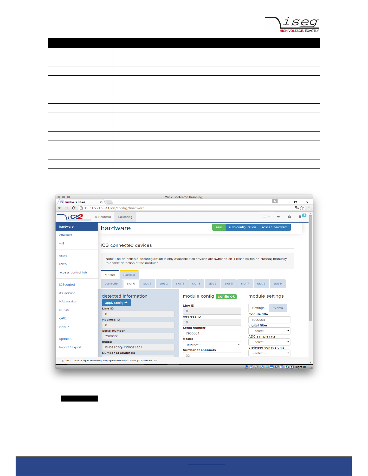
Hardware
In the hardware section, all iCS connected devices like connected crates, controllers and modules are listed and configurable.
Each device is represented by a tab, modules and controllers are nested into their responding crates. The CAN lines of the crates
are presented with a yellow or green upper tab border (corresponding to yellow or green CAN line), master crates and modules in
legacy crates with a blue upper tab border.
Crate Controller CC24/CC23 | v1.4 Last change on: 07.04.2017 | www.iseg-hv.com 16/28
Page 17

The configuration is stored independently from the current hardware setup or connected states. This gives the opportunity to
detect misconfigurations and recent hardware setups can easily be restored.
To apply the complete detected hardware state into the configuration use the „auto configuration“ button after triggering a
rescan using the „ rescan hardware “ button.
To apply the detected config of just one device (controller or module) use the „apply config“ button under each single tab.
The devices information is stored with the information of „module/device config“ column. Here the line and address ID are shown
and a serial number can be entered (or applied by using auto configuration / apply). If the model of the hardware device could be
detected automatically, a model is selected in the dropdown list, otherwise it should be selected manually.
HARDWARE TYPES
Device Standalone High Voltage Power Supply
Crate Case / Bin for a modular HV-supply (module), which supplies power
Controller Special controller card used in a crate to control, monitors and manages nested modules and Crate
functions, like switch ON/OFF of Crate power supply, monitor temperatures, fans, UPS and more
Module Modular High Voltage Power Supply, plugged in a slot of a crate, supplied by a CRATE, communication
and management by CRATE CONTROLLER, no own POWER ON feature
Information in the row „module settings /device settings“ are module / device specific settings and are stored into the XML
configuration file. These settings will get lost when using auto-configuration or apply config functionality.
Ethernet configuration
The ethernet settings of the iCS server hardware (CC2x Crate Controller, iCSmini) can be changed under the ethernet tab. By
turning DHCP Client to enabled the iCS will try to obtain an IP address from the local networks DHCP server. Otherwise the IP can
be set fixed. Therefore DHCP client must be disabled and IP v4.0 settings can be entered manually.
ETHERNET FACTORY DEFAULTS
IP DHCP
GATEWAY empty
NAMESERVER empty
DNS empty
TIMESERVER empty
(Re)set / ethernet configuration
You can reset the ethernet configuration and also set to fixed IP adress e.g. cause of problems with DHCP IP relay using the
following procedure:
1. Shut down all modules/devices and turn off the iCS System by unplugging mains.
2. Create an empty file called “RESET_NET.txt” on a USB flash drive (FAT32 format)
3. Now edit the file. It should contain the following entries, separated by new lines.
CONTENT OF RESET_NET.txt
LINE PARAMETER EXAMPLE DEFAULT-VALUE
0 IP adress / DHCP 192.168.2.10 DHCP
1 NET MASK 255.255.255.0 255.255.255.0
2 GATEWAY 192.168.2.1 192.168.16.1
3 NAMESERVER 192.168.2.1 192.168.16.1
4. Plug USB flash drive into the USB slot at the front panel of the Crate-Controller / one USB slot of iCSmini2
5. Plug in mains
Crate Controller CC24/CC23 | v1.4 Last change on: 07.04.2017 | www.iseg-hv.com 17/28
Page 18

6. Please wait about 20 seconds until iCS has started completely
7. optional: Plug off the USB flash drive and check on a computer if the file created on point 2 is still there.
Check if RESET_NET.txt was renamed into RESET_NET.txt.done on success.
WiFi configuration
The WiFi configuration can change configuration of the wireless network provided by the iCS hardware access point (optional).
Generally the WiFi function can be disabled using the WiFi support switch. The IP address of the WiFi is fixed, so once connected
with a iCS WiFi the IP stays always the same.
WIFI FACTORY DEFAULTS
IP (fixed) 192.168.1.1
SSID iseg-iCS2_[HARDWARE SERIAL-NUMBER ]
Channel 5
Password password
Users / roles configuration
Users of iCScontrol can be added, edited and removed in the users section. Users of iCScontrol can be added, edited and
removed in the users section. Users can be assigned roles, such like admin, user etc. One or more users can be selected by
editing a role.
USER DEFAULTS
User admin
Password password
Role admin
Access control lists (ACL)
With the access control list rights to grant or forbid control on special objects for principals (roles or users) is managed. This gives
a powerful tool for very detailled right mechanism.
INFORMATION
NOTE
Note: Users, roles and ACL are only applied for user authentication for applications and services, which
are based on iCSservice. These are iCScontrol, iCSconfig, isegControl, SOAP and HTTP API.
isegHAL based services should implement own security mechanisms .
SSH access
The ICS2 Linux host system can be fully accessed as root user using a encrypted SSH shell access over port 22.
This enables user to install own services or freely configure, e.g.EPICS plugins etc.
INFORMATION
The local filesystem is divided into a system and a user data partition. To make changes on the readonly
Crate Controller CC24/CC23 | v1.4 Last change on: 07.04.2017 | www.iseg-hv.com 18/28
Page 19

NOTE mounted system part use the following command: mount / -o remount,rw
(Re)set SSH access
INFORMATION
NOTE
To protect your iCS system we strongly advice to change the standard factory password into a new
userdefined one. Keep this password secret!
For security reasons this is only possible with direct hardware access using the following procedure:
1. Create a file RESET_SSH.txt with your new Root Passwort as content in the first line and save it to an USB flash memory
(FAT32 format). Note: if the file is emtpy, the iCS root password will be reset to factory default
2. Plug the stick into iCS hardware and resboot iCS.
3. The iCS changes the password during the boot process. In case of success the file will be renamed into
RESET_SSH.txt.done.
iCS Factory Reset Invocation
In case the user has forgotten his password or simply wants to get back to factory default configuration, it is possible to invoke a
factory reset. For factory reset a USB flash drive (USB stick) with a FAT32/FAT16 partition is needed.
ATTENTION
CAUTION
After factory reset all hardware configurations will get lost!
Instructions
1. Shut down all modules / devices and turn off the iCS System by unplugging mains.
2. On the USB flash drive create an empty file called “RESET_ICS.txt”
3. Plug USB flash drive into the USB slot at the front panel of the Crate-Controller
4. Plug in mains
5. Please wait about 20 seconds until iCS has started completely
6. optional: Plug off the USB flash drive and check on a computer if the file created on point 2 is still there.
If not, the factory reset was succesful.
Crate Controller CC24/CC23 | v1.4 Last change on: 07.04.2017 | www.iseg-hv.com 19/28
Page 20

iCSservice configuration
The iCSservice running on crate controller or iCSmini hardware provide two interfaces, a websocket push technology interface
and a HTTP polling interface, which is fallback for browsers and clients, that do not support websocket technology. Both of them
can be disabled, whereas at least one of them is necessary for the correct operation of iCScontrol.
iCSservice DEFAULTS
Websocket Port 8080
HTTP port 80
HTTP URL BASE <IP-of-iCSmini>/api/
HTTP interface
This interface gives quick access to iCSservice by simple HTTP queries.
iCSservice HTTP functions
URL, Parameters with leading $, params not mandatory [$param] Response Description
http://<IP-of-iCSmini>/api/lgetItemsInfo XML XML with item object
information
http://<IP-of-iCSmini>/api/login/$username/$password API Key Returns API Key to be identified
for session
Crate Controller CC24/CC23 | v1.4 Last change on: 07.04.2017 | www.iseg-hv.com 20/28
Page 21

http://<IP-of-iCSmini>/api/logout/$session-ID TRUE / FALSE
http://<IP-of-iCSmini>/api/getItem/$apikey/$line/$address/$channel/$item JSON Object Returns state of a specific item
of a hardware path
$line, $address, $channel and
$item can be set by wildcard '*'
http://<IP-of-iCSmini>/api/setItem/$apikey/$line/$address/$channel/$item/
$value/[$unit]
TRUE / FALSE Sets state of a specific item of a
hardware path
$line, $address, $channel can
be set by wildcard '*'
http://<IP-of-iCSmini>/api/getUpdate/$apikey/ JSON Object returns all changes collected by
iCSservice since last getUpdate
call for this client session
Use “*” as wildcard, e.g. to set or get items on multiple channels at once.
Use “null” as empty set identifier, e.g. to obtain module specific objects without channel declaration.
EXAMPLES
http://192.168.1.1/api/getItem/123456-321/0/ 1/0/Status.voltageMeasure Returns voltage value, unit and timestamp of
channel 0 of module with address 1 of line 0
http://192.168.1.1/api/ s etItem/123456-321/0/ 1/*/Control.voltageSet/1/kV Set set voltages of all channels of module 1 in
line 0 to 1,000 Volt
http://192.168.1.1/api/ s etItem/123456-321/0/ null/null/Control.power/1 Switch controller of line 0 (master) on
EPICS
For the use of iseg hardware with Experimental Physics and Industrial Control System (EPICS) the iCS comes with a preinstalled
integrated Input-Output-Controller (IOC). This service can be enabled or disabled using the switch „enable EPICS input / output
controller“. To keep things straight-forward the iCS can generate IOC configuration files (.db and .sub), using the current hardware
configuration. Both files can be downloaded to the local computer, be edited manually, e.g. with a text editor and be uploaded
again. This gives a quick start to run an IOC out of the box. To get an overview on all available process variables (PV), which are
generated at the start of IOC, the PV list can be downloaded using the respective button. The IOC script combines a process
variable definition file (.db) with a substitution file (.sub), which contains hardware setup information and placeholders to create
all accessable process-variables at runtime.
File Description Sample content (extraction)
iseg_epics.db Database file with definitions
of PV
#############################
# ### Crate item values ### #
#############################
record( mbbiDirect, "ISEG:${CONTROLLER_SN}:${CAN_LINE}:$
{DEVICE_ID}:StatusLow" ) {
field( DESC, "Lower 16 bit of module status register" )
field( DTYP, "isegHAL" )
field( INP, "@${CAN_LINE}.${DEVICE_ID}.Status" )
field( NOBT, "16" )
field( SHFT, "0" )
field( TSE, "-2" )
}
...
iseg_epics.sub Substitution file contains a
pattern that will be
substituted by the following
lines for each corresponding
channel
{CONTROLLER_SN,CAN_LINE,DEVICE_ID,MODULE_ID,CHANNEL_ID}
{5230003,0,1000,0,0}
{5230003,0,1000,0,1}
{5230003,0,1000,0,2}
...
iseg_epics.pv Text file with list of process
variables generated
ISEG:5230003:0:0:0:CurrentMeasure
ISEG:5230003:0:0:0:CurrentNominal
Crate Controller CC24/CC23 | v1.4 Last change on: 07.04.2017 | www.iseg-hv.com 21/28
Page 22

ISEG:5230003:0:0:0:VoltageMeasure
ISEG:5230003:0:0:0:VoltageNominal
...
For more detailed information on EPICS, please visit: http://www.aps.anl.gov/epics/, for sample libraries and test scripts, please
contact support @iseg-hv.de.
isegHALService
The isegHALservice provides a secure sockets encrypted end-to-endpoint access to iseg Hardware layer running on crate
Controller / iCSmini hardware. The isegHALservice API is similar to isegHALapi with some specific extension. Please refer
Appendix “isegHAL” for details. For an easy start a simple example program isegHalRemoteExample demonstrates the remote
access. There are virtual instruments (VIs) which are based on the library “isegHAL-remote” in order to control iseg hardware via
LabVIEW4.
SNMPservice
For backward compatbility of the iCS2 to SNMP controlled systems like WIENER mPOD iCS2 is able to communicate using the
SNMP service.
The service can be enabled or disabled using the switch „enable SNMP interface“.
Using the current iCS2 hardware configuration a SNMP configuration can be automatically generated. To create a new SNMP
configuration, which is compatible to WIENER Configuration file (.mib) please use button “generate configuration” under the
SNMP tab in iCSconfig.
For user specific changes of configuration, the .mib (vendor specific definition of datapoints) and .sub (substition information with
list of hardware channels) files can be downloaded, locally modified and reuploaded.
Please note: local modifications will overwritten every time the “generate configuration” function will be used.
Software architecture of the iCS2 system
4 Copyright National Instruments
Crate Controller CC24/CC23 | v1.4 Last change on: 07.04.2017 | www.iseg-hv.com 22/28
Page 23

Updates
The following types of updates can be managed with iCS:
Type Description
base product database with information about iseg hardware specifications
system update image of the iCS server operating system (CC, iCSmini)
firmware firmware update files for iseg devices (like HV modules, crate controllers etc.)
All update files can be downloaded from iseg web repository using the check online for updates or using the update upload
function to send a file from local computer to iCS server.
Once an update file is available on the iCS it can be installed using install or removed by using delete Buttons. After using install,
follow the instructions shown on the screen.
Firmware files can be unzipped using extract. After extraction the available firmware files are shown in a list. By clicking install the
iCS tries to apply the selected firmware to all connected devices, that are qualified for (matching item code, online, lower
firmware version installed).
To update specific hardware devices please extract the firmware package first and then navigate in the hardware section to the
corresponding device and use firmware update functionality individually.
Crate Controller CC24/CC23 | v1.4 Last change on: 07.04.2017 | www.iseg-hv.com 23/28
Figure: iCS2 software architecture / supported hardware
Page 24

INFORMATION
NOTE
Using the “Check online for updates” feature the iCS directly connects to iseg online software repository.
All update files can also be downloaded from iseg website (http://iseg-hv.com/en/support/downloads)
or directly on http://download.iseg-hv.com/
Crate Controller CC24/CC23 | v1.4 Last change on: 07.04.2017 | www.iseg-hv.com 24/28
Page 25

iCScontrol – control and monitor web application
The user interface of iCScontrol software is divided into three bars.
Left bar: Hardware Explorer
The left column shows the configured hardware.
If connected with iseg CAN line management slaves are shown in yellow or green background, corresponding to the CAN line they
are connected with. Every device has a colored left border showing the running state.
Crate/Device running states
grey one of the nested modules is ramping to the desired voltage
yellow one channel of one of the nested channels is ramping to the desired voltage
red the crate / device (or one of the nested modules/channels) has one or more errors (refer to the error/event
badges)
green the crate / device (and all of the nested modules) are in a good condition, at least one channel of a nested
module is running high voltage
Module running states
grey not present, not connected or switched off
Crate Controller CC24/CC23 | v1.4 Last change on: 07.04.2017 | www.iseg-hv.com 25/28
Page 26

yellow one channel of the module is ramping to the desired voltage
red the module has one or more errors (refer to the error/event badges)
green the device/module is in a good condition, at least one channel is running high voltage
Channel running states
blurred / faded out Module is not detected (propably switched off)
grey not present (configured module to current module mismatch), or switched off
yellow channel is ramping to the desired set voltage
red channel has at least one error (please inspect error counter badge)
green channel is in good condition and switched on
Left bar: Channel folders
Channel folders are shown in the section “channel folders” below the hardware section in the left application bar. Channel folders
can be created and extended by selecting a set of channels and clicking the folders icon on top of the channel list.
Existing folders can be selected or removed in the folders section of the left bar.
Left bar: Channel profiles
Channel profiles store information about set values, On/off states, and Kill-Properties of channels. They can be created by
selecting the channels that should be restored in the channel list and clicking the star-icon. Existing profiles can be selected,
applied and removed in the channel profiles section of the left bar. A new option with the custom given title appears in the Select
Box. By selecting a Channel profile and clicking the apply button the stored state of the channel will be adjusted.
Center bar: Channel list
Once a device or channel folder has been selected, the channel list will update and show only the corresponding channels, with
• The topological location (line, address, channel),
• The running state,
• Set and measured values,
• Channel infos, events and errors (displayed as clickable badges)
The list header has an action row, where all channels can be selected with one click for more actions.
Each action in this row is located in top of its respective column.
Some examples:
• To create a new channel folder of specific channels, select these channels and click the folder-icon.
• To store the current setup of the specific channels (running state, set-values, kill enable etc.), select them and click on
the star-icon. To enable or disable all selected channels, click the ON / OFF icons.
• Change the set voltages of all selected channels, click the edit-icon which is located in the Vset column.
• To display a graph of measured voltages of all selected channels, click on the graph-icon located in the Vmeas column.
• To show a live log of measured voltages of all selected channels, click on the logtable-icon located in the Vmeas column.
Center bar: Chart
At the bottom of the center bar a floating chart window can be shown over the channel list by clicking the toggle button with the
chart icon on the upper left of the chart bar. To show only specific channel information, please select the channels to display and
select the Chart-Icon on top of the respective column of the action row, e.g. to display the voltages of the selected channels,
select them and click on the Chart-Icon on top of Vmeas column. To show plots of all channels select or deselect all channels, and
disable/re-enable the chart by clicking the chart icon twice.
Crate Controller CC24/CC23 | v1.4 Last change on: 07.04.2017 | www.iseg-hv.com 26/28
Page 27

Right bar: Device information
The device section gives information on the currently selected hardware device of the device explorer. Depending on the device
type, hardware status information are given (temperature, error, safety loop states), the device can be enabled / disabled. Device
specific parameters can be set (ramps, kill parameters …). To get a quick help, hardware documentation can be downloaded
directly.
Right bar: Camera
The camera tab shows the captured image of the configured camera. It can be directly connected with the iCS hardware or an IP-
Cam URL, configured in hardware / iCScontrol section.
Right bar: Live log
The live log collects information of the current session. The log data is only available until a reload of the iCScontrol webpage
occurs. The live log can be filtered to specific channels or value types, by selecting channels and clicking the corresponding log
icon in the action row on top of the channel list. The log list shows the last value of an item. By clicking on it, previsios log items
are displayed.
All session log data can be exported as CSV file for ongoing work with Spreadsheet applications, eg. Microsoft® Excel.
Right bar: Commands
Commands can be send directly to connected devices. Quick commands are mass operations that can be sent to more devices at
one time. The commands tab prefills the input fields according to the selected hardware device (device explorer).
13 Appendix
For more information please use the following download link:s
CAN EDCP Programmers-Guide
http://download.iseg-hv.com/documentation/SYSTEMS/Manuals/English/MMS/CAN_EDCP_Programmers-Guide.pdf
Crate Controller CC24/CC23 | v1.4 Last change on: 07.04.2017 | www.iseg-hv.com 27/28
Page 28

14 Manufacturer´s contact
iseg Spezialelektronik GmbH
Bautzner Landstr. 23
01454 Radeberg / OT Rossendorf Germany
Direct
Fon: +49 351 26996-0
Fax: +49 351 26996-21
Internet
www.iseg-hv.com
www.iseg-hv.de
E-Mail
support @ iseg-hv.de
sales @ iseg-hv.de
 Loading...