

Page 1
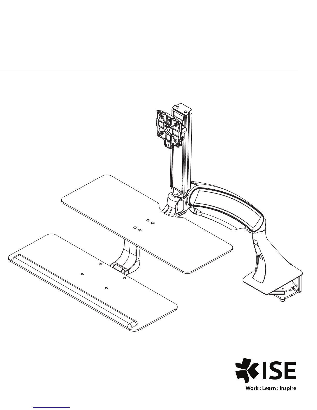
INSTALLATION MANUAL FOR
ACTIVATE SIT-STAND WORKSTATION
Maximum Load
Single Monitor Arm: 23 lbs.
Dual Monitor Arm: 19 lbs.
Monitor Weight
Single Monitor up to 20 lbs.
Dual Monitors up to 8 lbs. each
Page 2
Contents
Tools Required / Supplied Part Kits / Warnings/Disclaimer .........2
Possible Base Mounting Orientation
Clamp Mount Base Orientation ........................................3
Grommet Mount Base Orientation .................................... 4
Attaching the Arm to the base .................................................5
Installing the Work Surface ...................................................... 5
Installing Keyboard Tray .......................................................... 5
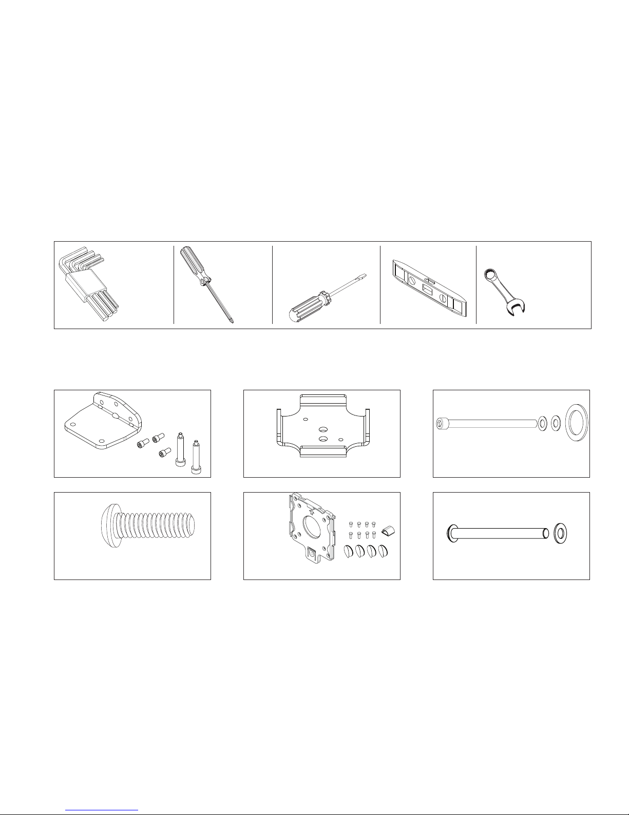
Tools Required
Keyboard Tilt .......................................................................... 6
Keyboard Storage Stop ............................................................6
Installing the Monitor .............................................................6
Cable Management Installation ............................................... 7
Arm Counterbalance Adjustments ............................................ 7
Tray Leveling Adjustments (Left to Right) ..................................8
Tension Adjustment for the Monitor ......................................... 8
Monitor Tilt Tension Adjustment ............................................... 8
Allen Keys,
1/8",3/16",
7/32",1/4"
(provided)
#2 Phillips
Screwdriver
Supplied Part Kits
KIT A: Bottom Clamp Kit
Slotted
Screwdriver
Level
3/8" Wrench
(for Dual Monitor option)
KIT B: Clamp Plate KIT C: Arm Bolt/Washer Kit
KIT D:
Tray Head Bolt
Warnings/Disclaimers
INSTALLATION WARNINGS:
•
Read the entire instruction manual before beginning any installation or assembly.
•
The installer must verify that the attachment surface can safely support the
combined weight of all the attached equipment and hardware.
•
Improper installation of this product may cause extensive property damage
or serious personal injury, either during or after installation.
DISCLAIMER:
•
The manufacturer will bear no responsibility for any damages of any kind
arising from improper installation of this product.
•
In no way will the manufacturer be held liable for any damage
to the monitor, property or personal injury should an outside force either
intentionally or unintentional be applied to the monitor or monitor
mounting bracket
KIT E: VESA
Mounting Plate Kit
2
KIT F: Grommet Mounting Bolt
ADJUSTMENT NOTIFICATION:
•
Routine maintenance checks and adjustments are suggested to properly
support the quality and optimal performance of this product.
Refer to adjustment suggestions on last page of booklet, or contact your
distributor for further detailed information.
•
Over tightening of bolts during installation or adjustments can damage
the product and affect the function and warranty.
Page 3
Clamp Mount Base Orientation
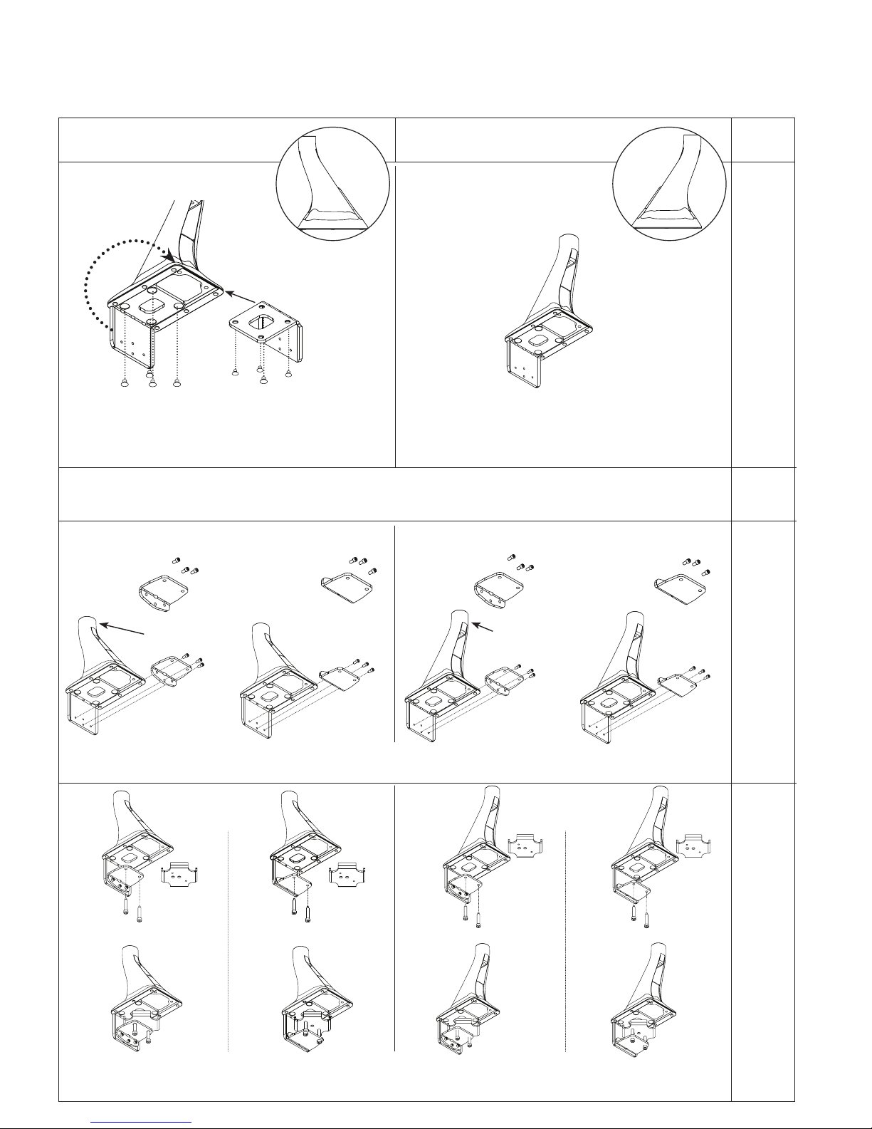
The unit can be installed on a 24” or 30” deep rectangular or corner desk using the integral desk clamp or grommet mounting
hardware provided. The factory setting is for a 30” deep desk clamp mount application.
24" DEEP DESK
INSTALL THE BASE REAR FACING
STEP 1 STEP 1
Reverse the angle bracket. Take the base assembly from the box.
Use the 7/32" Allen Key to remove the four screws holding the angle
bracket to the base. Reposition the angle bracket per the drawing and
re-secure the angle bracket with the four screws just removed.
Place the base in the desired location at the back of the desk. The angle bracket should slide down the back of the desk.
STEP 3 STEP 3
Desks ¾”-1 ½” thick,
Bottom Clamp is
UPWARD
Desks 1 ½”-2 ½”thick,
Bottom Clamp is
DOWNWARD
30" DEEP DESK
INSTALL THE BASE FORWARD FACING
Base is already in the forward facing position (factory preset).
Proceed to STEP 2.
STEP 2
Desks ¾”-1 ½” thick,
Bottom Clamp is
UPWARD
Desks 1 ½”-2 ½”thick,
Bottom Clamp is
DOWNWARD
32"+
STEP 1
N/A
STEP 2
N/A
STEP 3
N/A
Base REAR facing.
Using KIT A: Bottom Clamp Kit - attach bottom clamp to the angle bracket with the three 1/2" socket head cap screws.
Tighten with 3/16" Allen Key.
Base FORWARD facing.
STEP 4 STEP 4
Desks ¾”-1 ½” thick Desks ¾”-1 ½” thick
Desks 1 ½”-2 ½”thick Desks 1 ½”-2 ½”thick
STEP 4
N/A
Insert the two 2" bolts into the bottom clamp. Position the clamp plate (KIT B: Clamp Plate) - facing up over the tips of the bolts.
Tighten alternatively each bolt to 75 in/lbs. with the 7/32" Allen Key to firmly secure the base to the desk.
3
Page 4
Grommet Mount Base Orientation
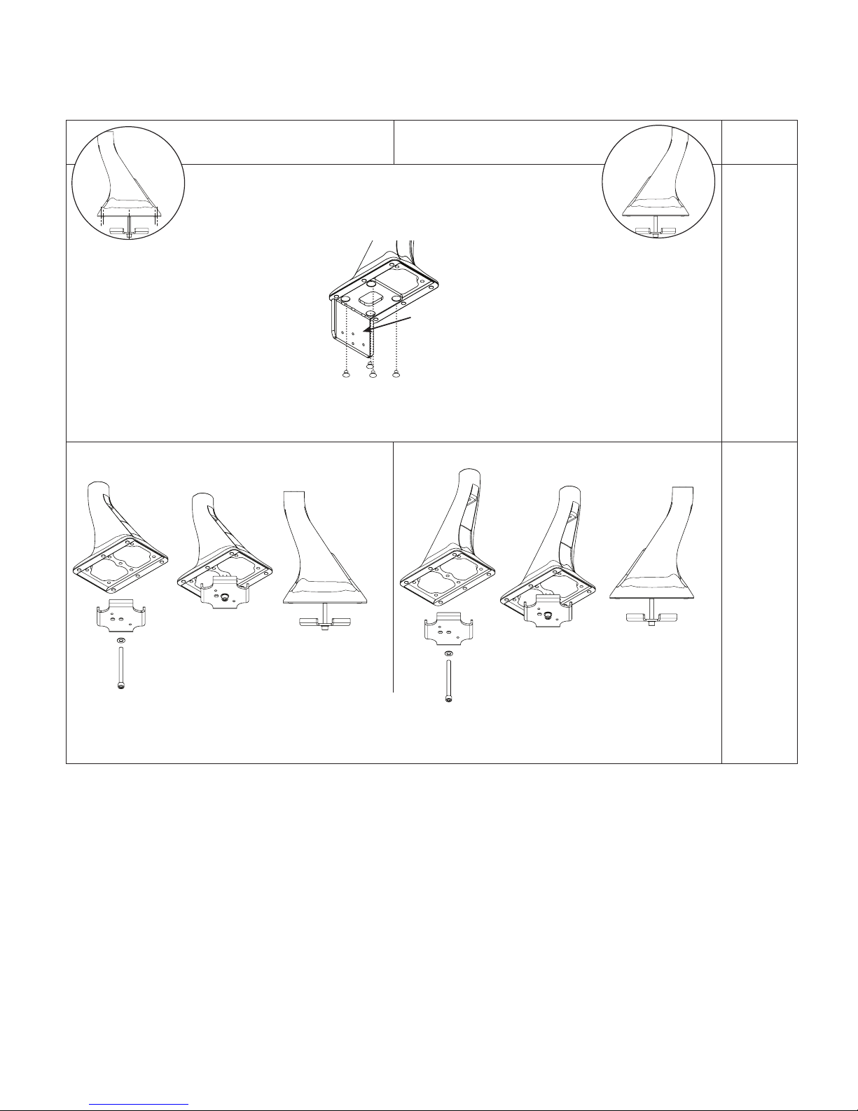
If installer is drilling their own hole, ensure that the diameter is a minimum of 1/2".
24" DEEP DESK
INSTALL THE BASE REAR FACING
SAME FOR 24" & 30"
Take the base assembly from the box and remove the angle bracket (not used in a grommet application).
Use the 7/32” Allen Key to remove the four screws holding the angle bracket to the base.
STEP 2 STEP 2 STEP 2
30" DEEP DESK
INSTALL THE BASE FORWARD FACING
STEP 1
Remove
Angle Bracket
32"+
STEP 1
See 30"
DEEP DESK
Base
should be
forward
facing
See 30"
DEEP DESK
Base
should be
forward
facing
BASE MUST BE IN THE REAR FACING POSITION BASE MUST BE IN THE FORWARD FACING POSITION
Insert the grommet bolt through the washer (KIT C: Arm Bolt/Washer Kit) and upward facing clamp plate (KIT B: Clamp Plate). From
under the desk insert the grommet bolt assembly through the desk into the center hole of the base. Use 7/32" Allen Key tighten and
secure to 75 in/lbs.
4
Page 5
Attaching the Arm to the Base
With the base already installed
STEP 3
With arm in the lowest
NOTE: Ensure
nylon bushing is
on the arm post
when inserting the
arm iinto the base.
STEP 2
STEP 1
Slide the large nylon washer
(KIT C: Arm Bolt/Washer Kit)
over the bottom pin of the
arm.
STEP 2
Set the main arm pin into
the base.
STEP 1
position remove the plastic cap
at the back of the arm.
STEP 4
Keeping the arm in lowest
position,
insert the bolt/
washer assembly (KIT C:
Arm Bolt/Washer Kit) into
the back of the arm.
NOTE: Place nylon washer
on bolt first, followed by
metal washer
Installing the Work Surface
STEP 1
Position the work surface on the tray support arm as shown. Do not remove the tape
from the underside of the tray support arm. Align the four holes in work surface with
the four front holes in the tray support arm.
STEP 2
Remove the four screws from the bag taped to the work surface. Hand thread each
screw into the four holes in the worksurface (the nuts have been pre-mounted on the
underside of the tray support arm and are held in place by the tape).
STEP 3
Remove the tape from the underside of the tray support arm. You can now tighten the
screws and nuts using the Philips screwdriver for the screws and the Slotted screwdriver
for the nuts.
STEP 4
STEP 5
STEP 6
STEP 5
Keeping the arm down tighten
the bolt with the 7/32” Allen
Key until bolt is seated. Tighten
or loosen bolt to obtain desired
resistance for left to right arm
movement.
STEP 6
Replace the trim cap at the back of the arm.
Installing the Keyboard Tray
STEP 1
Slide the keyboard tray head
into place as shown.
STEP 2
Adjust the keyboard tray head to the
desired height, and tighten into place
using the Tray Head Bolt (KIT D) and
3/16” Allen key.
STEP 3
The keyboard tray can be mounted
to the tray head in two positions.
The front position will place the
keyboard tray (and the user’s
keyboard) closer to the monitor.
The back position will increase
the focal distance by placing the
keyboard tray further from the
monitor.
Front Position
5
Back Position
Position the keyboard tray on the tray head, align the four holes in
the keyboard tray to the tray head, and secure in place using the
screw pack taped to the keyboard tray. Note, insert plastic washer
onto screw first, followed by the metal washer and nut.
STEP 4
Use two sided 3M Hook and Loop pads to secure keyboard to tray.
Page 6
Keyboard Tilt
(+10° to -15°)
Keyboard Storage Stop
STEP 1
To adjust the keyboard tray angle, turn the knob clockwise
or counterclockwise, to attain the desired angle.
STEP 1
To adjust the maximum storage angle, place tray
in the maximum storage location and tighten rear
set screw with the 1/8” Allen Key.
Installing the Monitor (5 lbs. to 20 lbs.)
For this step, the installer needs to determine if they wish to use the Quick Connect adapter
supplied or mount the monitor directly to the VESA mount on the Float Tower.
SINGLE-MONITOR
STEP 1
If using Quick Connect adapter, mount the Quick Connect
adapter (Kit E: VESA Mounting Plate Kit) to back of the
monitor with the M4 pan head screws provided.
Use a #2 Phillips screwdriver to secure screws. Lift
monitor into position and slide the Quick Connect onto
the VESA.
STEP 2
If not using the Quick Connect adapter, mount the
monitor directly to the VESA plate on the Float Tower with
the supplied M4 pan head screws provided. Use a #2
Phillips screwdriver to secure.
DUAL-MONITOR (Optional Dual Monitor
Kit)
STEP 1
Attach the dual bracket to the Float Tower VESA with the hardware
provided in the Dual Monitor Kit.
To attach monitors see steps for single-monitor.
NOTE: Adjustable bracket supports most 24" monitors
weighing up to 8 lbs. each.
6
Page 7
Cable Management Installation
+
–
After the technology has been installed, ensure there is enough slack in the cables from
the monitor, keyboard and mouse along with any other peripherals.
STEP 1
STEP 2
STEP 1
Use a #2 Phillips screwdriver to
remove the four screws securing
the cable management tray.
STEP 2
Remove the steel insert from the
cable management tray. Note
orientation of steel insert in cable
management tray.
STEP 3
STEP 4
STEP 3
Lay all cables (e.g. power, VGA
and mouse cables) into the cable
management tray.
STEP 4
Re-assemble steel insert from
STEP 3 with counter sinks to the
bottom of the cable management
tray and notch at the back.
STEP 5
Re-attach the cable management tray with
the four #2 Phillips screws removed in STEP 1.
STEP 6
Cables can be routed through the desk base
and into the grommet hole if applicable.
STEP 7
Adhesive cable clips are supplied and can be
used to secure loose cables as required.
STEP 7
STEP 5
STEP 6
Arm Counterbalance Adjustments
Arm adjustment is to be made after all technology has been installed from 5 lbs. to 20 lbs.
ATTENTION:
Arm must be held down to perform this adjustments.
STEP 1
Remove the trim cap at the back
of the arm.
STEP 2
Use the 1/4” Allen Key to turn
the middle bolt at the back
of the arm. Turning the bolt
clockwise decreases the spring
force reducing the counter
balance load. Turning the bolt
counterclockwise increases
the spring force increasing the
counter
balance load.
STEP 3
Adjust the middle bolt until the
arm counter balance is acceptable.
STEP 4
Replace the trim cap at the back
of the arm.
STEP 2 & 3
1/4”
Allen Key
STEP 4
COUNTERBALANCE
ADJUST
+–
!
Do not overtighten
bolt as this may cause
damage to the product.
7
Page 8
Tray Leveling Adjustments (Left to Right)
+
–
+ –
+–
Tray adjustment is to be made after all technology has been installed.
ATTENTION:
Tray must be parallel to the work surface and swiveled
90° to the base when adjusting.
STEP 1
Remove the trim cap at the back of the arm.
STEP 2
Use the 3/16” Allen Key to turn the top bolt at the
back of the arm. Turn the bolt until the tray is level.
STEP 3
Confirm that surface is level with spirit level.
STEP 4
Replace the trim cap at the back of the arm.
STEP 3
STEP 2
+ –
ADJUST
3/16”
Allen
Key
STEP 4
LEVEL
Tension Adjustment for the Monitor
STEP 1 & 3
STEP 1
Use the 3/16” Allen Key to remove the two
bolts securing the plastic top cap of the
Float Tower. Remove cap.
STEP 2
Remove and install pins as necessary per the
drawing while holding the monitor in the highest
position. If pins are not needed, keep them inserted
in the bracket hole for possible future use.
1. Remove
top cap
STEP 3
Once tension is acceptable, replace the cap and
secure with the screws mentioned in STEP 1.
Tighten with 3/16” Allen Key.
2. Hold monitor in the highest position.
3. Remove/install pins as necessary
Light monitor Medium monitor Heavy monitor
Monitor Tilt Tension Adjustment
ATTENTION:
Before adjusting the tension of the Float
Tower, ensure that the monitor is the highest
position on the Tower so that the spring tails
are no longer in tension.
TENSION ADJUSTMENT
STEP 1
To adjust the monitor tilt tension, use a 3/16”
Allen Key to adjust tension setting on the
both sides of the VESA plate. Setting number
1 is for the lightest monitor and 4 is for heavy
monitors. The factory default setting is 1.
STEP 2
Adjust the setting screw until a desirable
tension is achieved.
STEP 1 & 2
8
1. Adjust tension as necesssary
Light
monitor
4
1
2. Repeat on alternate side
3
2
Heavy
monitor
4
1
3
2
 Loading...