

RISE
Assembly Instructions
UPDATED
July 1, 2013
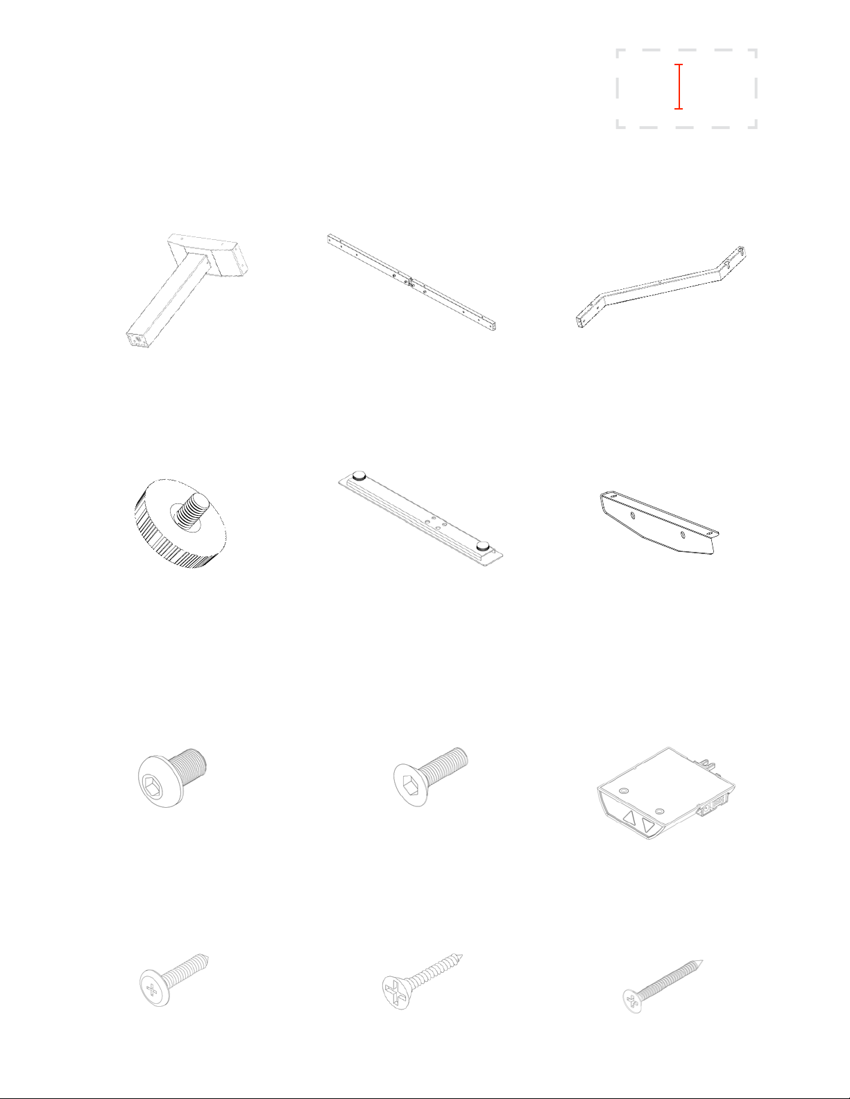
Part List: caution - only use the parts and hardware provided
[xx]
[93] - Silver
[01] - Black
68002348 [xx]
Height Adjustable Leg
2 pcs.
RISE - Glide
(attached to feet)
4 pcs.
68002547 [xx] - 29”- 45” or
54006700 [xx] - 44” - 75” or
68002513 [xx] - 76” - 90”
Adjustable Bar
1 pc.
68002505 [xx]
Foot
2 pcs.
68002509 [xx]
Kneesaver Z-Bar
2 pcs.
68001089
Side Support
2 pcs.
Fix-Kit- 1
M8 x 16mm
Panhead Bolt (Black)
8 pcs.
Fix-Kit- 4
3/16” x 3/4”
Panhead Wood Screw
6 pcs.
Fix-Kit- 2
M8 x 25mm
Countersunk Bolt (Silver)
8 pcs.
Fix-Kit- 5
1/8” x 5/8”
Countersunk Wood Screw
2 pcs.
68002462
Standard (2 leg)
Up/Down Switch
1 pcs.
Fix-Kit- 3
3/16” x 2-1/8”
Countersunk Wood Screw
8 pcs.
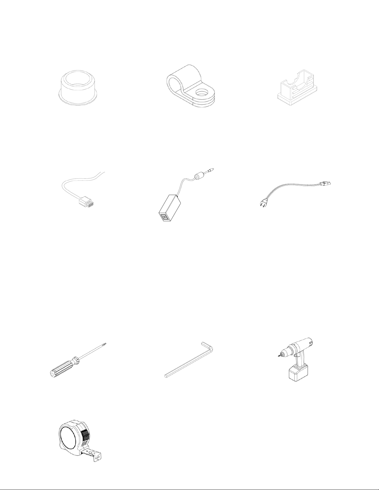
Fix-Kit- 6
Plastic Round Cap
12 pcs.
QKA - Tableclip
Plastic Wire Clip
6 pcs.
55750100
Plastic
Rectangular End-Cap
4 pcs.
68002462-PS
Leg Motor Cable
(attached to motors)
Power Adaptor
1 pc.
2 pcs.
Note: The hardware bag may contain extra components.
Tools Required:
68002462-PS-CABLE
Power Cable
1 pc.
Phillips Screwdriver M5 Hexagonal Wrench Electric Drill with
Phillips Head Bit
Tape Measure
Assembly Instructions: caution - please read notes carefully
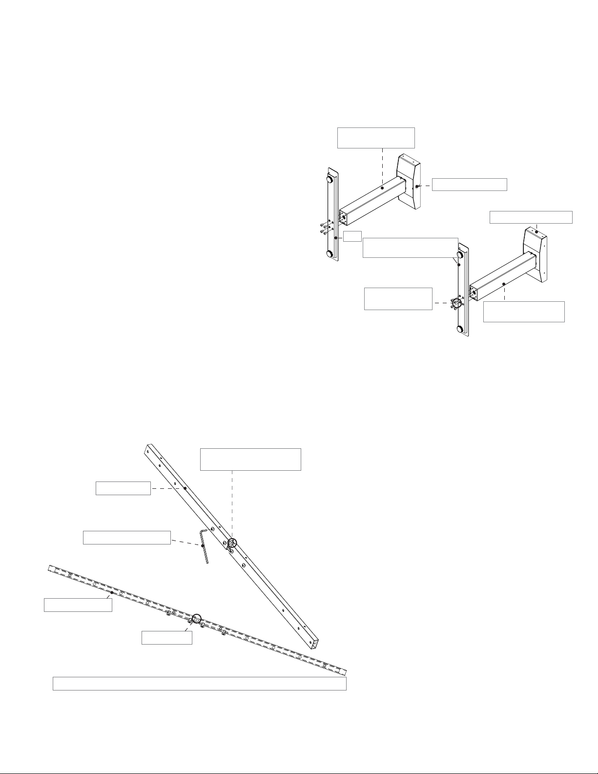
1. Attach Feet to Height Adjustable Legs
Position the 2 Height Adjustable Legs making sure
the wire cutouts on the Motor Housings are facing
each other.
Using an M5 Hexagonal Wrench attach the Feet to the
Height Adjustable Legs with 8 Black M8x16mm
Panhead Bolts. Make sure the longer sides of the Feet
are facing the front as shown in Figure 1.
Note: Both Height Adjustable Legs are identical.
Left Height Adjustable
Leg Sub-Assembly
Motor Housing Cutout
Foot
Longer side of the Feet to be
at the front of the desk
Black M8 x 16mm
Panhead Bolts
Figure 1. Attach Feet to Height Adjustable Legs
2. Adjust Adjustable Bar Width
Front of Motor Housing
Right Height Adjustable
Leg Sub-Assembly
Guiding hole for symmetrical
extension and retraction
Adjustable Bar
Loosen all 4 Center Bolts
Outer Square Tube
Inner Channel
Make sure all 4 holes on the Outer Square Tube align with the 4 holes of the Inner Channel
Figure 2. Adjust Adjustable Bar Width
Using an M5 Hexagonal Wrench, loosen the 4 Center
Bolts.
Expand or retract the Adjustable Bar to the desired
width while making sure the top holes of the Outer
Square Tube align with the holes of the Inner Channel.
Use the Center Hole of the Inner Channel as guide for
symmetry.
After achieving the desired width, tighten the 4 Center
Bolts to secure the Adjustable Bar subassembly. See
Figure 2.
Note: For Worksurfaces less than 48”, two crossbars
are provided.

3. Attach Adjustable Bar to Motor Housings
Facing the rear of the Height Adjustable Leg Assemblies, use an M5 Hexagonal Wrench to fasten the
Adjustable Bar with the 4 Silver M8x25mm Countersunk bolts onto the rear of the Motor Housings.
Make sure to use the 2 outer holes on each end of the Adjustable Bar.
The 4 Center Bolts of the Adjustable Bar should be facing forward towards the Motor Housings.
After fastening the Adjustable Bar, install the 2 Rectangular Plastic End-Caps on each end of the Adjustable
Bar. See Figure 3.
Rectangular Plastic End-Caps
Silver M8 x 25mm Countersunk Bolts
Adjustable Bar with 4 Center Bolts facing forwards
Rear of Motor Housing
Use Outer 2 holes
Figure 3. Attach Adjustable Bar to Motor Housings
Note: For worksurfaces less than 48”, attach crossbars to front and back of Motor Housing.

4. Attach the Kneesaver Z-Bars
Position the Sub-Assembly upright and face the front. The Adjustable Bar should be in the rear.
Loosen the 4 Adjusting Bolts in the middle of the Adjustable Bar while making sure to not change the width
alignment performed earlier.
Locate the slotted end of each Kneesaver Z-Bar and slide it between the Adjustable Bar and the back of the
Adjusting bolts. Tighten the bolts to secure the Kneesaver Z-Bars to the Adjustable Bar. Note: Both Kneesaver
Z-Bars are identical. See Figure 4.
Note: For worksurfaces less than 48”, Kneesaver Z-Bars are not provided.
Loosen Adjusting Bolts to
allow installation of Kneesaver
Z-Bars and tighten back after
positioning.
Figure 4. Attach Kneesaver Z-Bars to Adjustable Bar

After the Kneesaver Z-Bars have been fastened to the Adjustable Bar,
fasten the other ends of the Kneesaver Z-Bars to the front of the
Motor Housings using the 4 Silver M8x25mm Countersunk bolts.
Install the 2 Rectangular Plastic End-Caps. See Figure 5.
Silver M8 x 25mm
Countersunk Bolts
Figure 5. Attach Kneesaver Z-Bars to front of Motor Housings
Install the 8 Plastic Round Caps on the front of the Kneesaver Z-Bars.
See Figure 6.
Rectangular Plastic End-Caps
Plastic Round Caps
Figure 6. Attach Plastic Round Caps to front of Kneesaver Z-Bars
Install 6 Plastic Round Caps on the back of the Adjustable Bar.
See Figure 7.
Figure 7. Attach Plastic Round Caps to back of Adjustable Bar
Plastic Round Caps

NOTE:
· Ensure motor is properly positioned into the motor housing
· Ensure motor cable stain relief is positioned in the motor housing cut-out
· Ensure all motor connectors are properly connected
Connectors
Strain Relief
Motor Motor Housing

5. Install the Worksurface
Place the Worksurface on the oor with the bottom facing up. Make sure to lay it on a protective
layer to prevent scratching.
Using a tape measure, position the frame so that the distance between the back edge of the
Worksurface is 3” away from the back of the Adjustable Bar.
Depending on the size of the Worksurface selected, ensure to leave equal distances on both sides
of the frame.
Using an Electrical Drill with a Phillips Bit, fasten the frame onto the Worksurface with the 3/16” x
2-1/8” Countersunk Wood Screws. See Figure 8.
3/16” x 2-1/8” Countersunk
Wood Screws
Figure 8. Install the Worksurface
Note: For Bases 30” - 36” wide, refer to the last page for Side Support
Installation Instructions.

Note: For Digital Readout Memory Switch see seperate instruction guide.
6. Mount the Standard Up/Down Switch
Warning: Make sure the Power is disconnected until table is fully assembled
Select a convenient location on the underside of the Worksurface such that the Standard Up/Down
Switch can be easily accessed.
To mount the Standard Up/Down Switch use the 1/8” x 5/8” screws provided to fasten it on the
underside of the Worksurface in the location selected.
Connect the Motor Cables coming from each Height Adjustable Leg to the Standard Up/Down Switch.
Connect the Power Cable to the Standard Up/Down Switch.
Use the 6 Wire Clips and the 3/16”x3/4” Panhead Wood Screws to attach the Motor Cables and Power
Cable onto the underside of the Worksurface. See Figure 9.
1/8” x 5/8” Countersunk
Wood Screws
Figure 9. Mount the Standard Up/Down Switch

7. Initializing Instructions for Standard Up/Down Switch
Ensure the table is positioned in its nal location and that the Power Cord is plugged into an 110VAC
source.
Ensure all cables are properly connected.
1. Press and hold the UP and DOWN button at the same time on the Standard Up/Down Switch for
10 seconds
2. Press and hold the DOWN button to lower the table to its lowest point.
3. Table is ready to be used.
NOTE: It is sometimes necessary to press the DOWN button twice to start the
initialization as the system can be in dierent modes when initialization is
attempted.
Figure 10. Fully Assembled RISE Table

Side Support Installation Instructions - For bases 30” - 36” only
1. Install the two Side Supports with the four M8x25mm Countersunk Bolts onto the Left and Right
Motor Housings of the Rise base.
M8x25mm
Countersunk Bolt
Side Support
Figure 11. Installing Side Supports
 Loading...