


ISDNLINK™
INET-810
INET-820
INET-830
INET-850
ISDN Router
User’s Guide
P/N: 9560860000

FCC Statement
This device complies with Part 15 of the FCC Rules. Operation is subject to the
following two conditions:
(1) This device may not cause harmful interference.
(2) This device must accept any interference received, including interfer-
ence that may cause undesired operation.
CE Marking Warning
This is a Class A product. In a domestic environment this product may cause radio
interference in which case the user may be required to take adequate measures.
Copyright ©1999 Jan. All Rights Reserved.
Document Version: 1.0
All trademarks and trade names are the properties of their respective owners.

ii

TABLE OF CONTENTS
CHAPTER 1 ABOUT YOUR INTERNET ROUTER ........................................... 1
Internet Router Features................................................................................. 2
Requirements................................................................................................... 6
Package Contents............................................................................................. 6
Internet Router INET-810 and INET-830 ......................................................6
Internet Router INET-820 ............................................................................... 8
Internet Router INET-850 ............................................................................... 9
LED Indicators...............................................................................................10
Rear Panel Connectors & Switches................................................................12
DIP Switches...................................................................................................13
CHAPTER 2 SETUP: INTERNET ACCESS........................................................15
Overview.........................................................................................................15
Hardware Installation ....................................................................................15
Internet Router Configuration.......................................................................16
Basic Setup Screen..........................................................................................20
PC Configuration............................................................................................23
Operation – Internet Access...........................................................................24
CHAPTER 3 PRINTER SHARING......................................................................25
Overview.........................................................................................................25
Software Installation.......................................................................................25
PC Configuration............................................................................................26
CHAPTER 4 ADVANCED SETUP.......................................................................31
Advanced Setup Screen..................................................................................31
CHAPTER 5 ANALOG PORTS ...........................................................................33
Overview.........................................................................................................33
Data.................................................................................................................33
CHAPTER 6 DHCP...............................................................................................35
Overview.........................................................................................................35
DHCP Server Screen......................................................................................35
i

CHAPTER 7 ISDN................................................................................................. 37
Overview.........................................................................................................37
Data.................................................................................................................38
CHAPTER 8 ROUTING .......................................................................................39
Overview.........................................................................................................39
Internet Router Configuration....................................................................... 39
Router Configuration .....................................................................................41
Routing Example............................................................................................ 42
CHAPTER 9 SERIAL PORT................................................................................45
Overview.........................................................................................................45
Serial Port Configuration...............................................................................46
Advanced Port Settings.................................................................................. 48
Advanced Port Settings.................................................................................. 49
Script File....................................................................................................... 50
CompuServe Script.........................................................................................52
Operation........................................................................................................53
CHAPTER 10 STATUS & MONITORING .........................................................55
Overview.........................................................................................................55
Status Screen ..................................................................................................55
DHCP Status...................................................................................................56
ISDN Status ....................................................................................................57
Port Status/Test Screen..................................................................................59
ii

APPENDIX A TROUBLESHOOTING.................................................................64
Overview.........................................................................................................64
ISDN Line.......................................................................................................64
Internet Access................................................................................................65
Printer Sharing...............................................................................................66
APPENDIX B AT COMMANDS...........................................................................70
Required Settings............................................................................................70
Finding the current Initial String...................................................................70
AT Commands................................................................................................72
APPENDIX C WINDOWS PEER-TO-PEER.......................................................76
Overview.........................................................................................................76
Procedure........................................................................................................76
APPENDIX D SPECIFICATIONS........................................................................80
Internet Router INET-810 ..............................................................................77
Internet Router INET-820 ..............................................................................81
Internet Router INET-830 ........................................................................... 810
Internet Router INET-850 ..............................................................................83
iii

This page was deliberately left blank.
iv
Chapter 1
1
C
About your Internet
Router
This Chapter provides an overview of the Internet Router's features and capabilities.
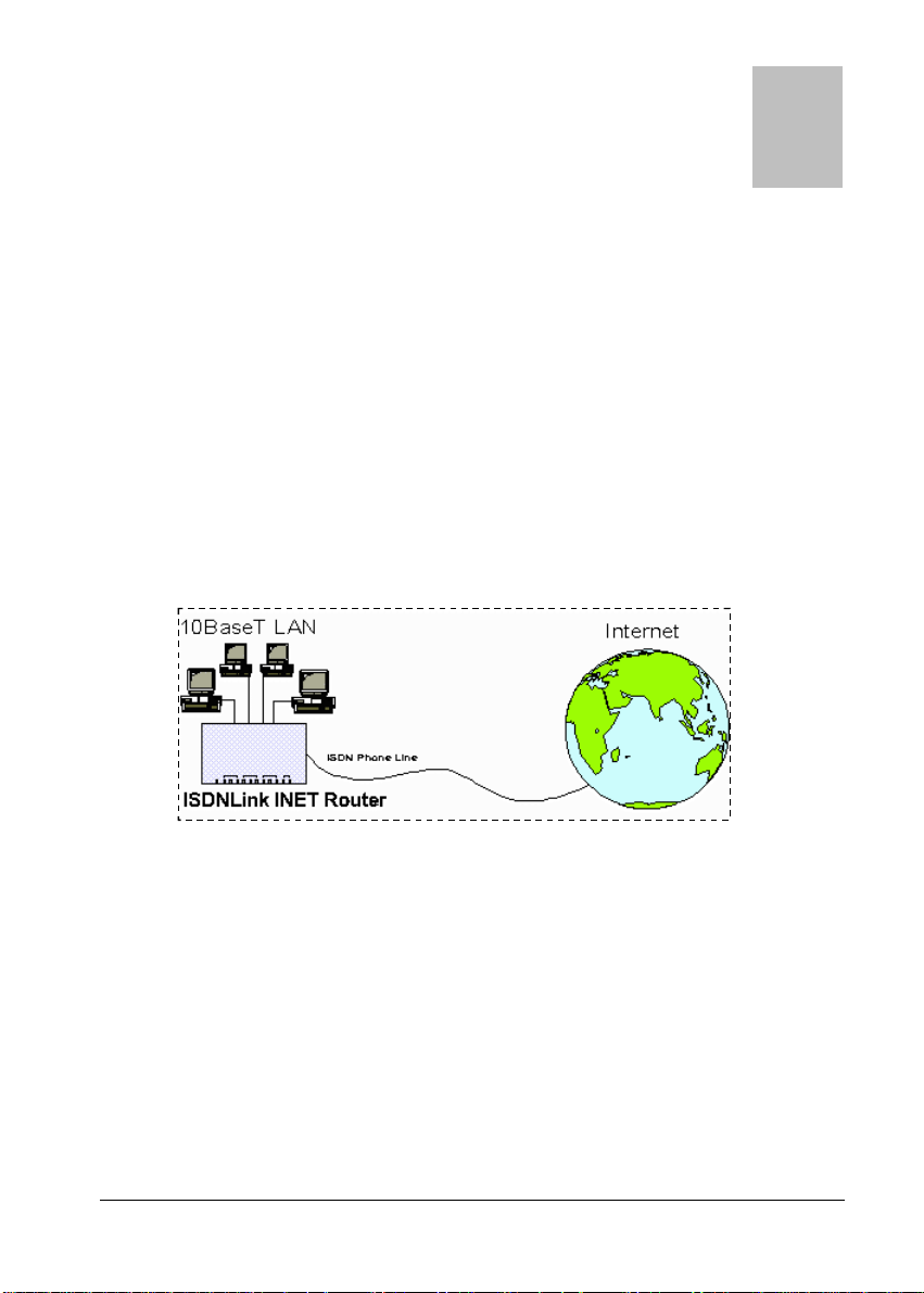
ongratulations on the purchase of your new Internet Router. The Internet
Router allows multiple SOHO (Small Office Home Office) users to share a single
Internet user account over an ISDN phone link. It provides the cost-effective
solution of giving users of your network easy access to the vast resources available
on the Internet.
Figure 1: Office to Internet
All of the Internet Router models include a built-in 4 port 10BaseT hub, allowing
you to easily create a peer-to-peer network.
Internet Router INET-830 and INET-850 include two (2) analog a/b ports, allowing
you to connect the analog a/b (POTS) telephone, answering machine, or fax.
For added versatility, the Internet Router INET-830 and INET-850 include a
printer port, allowing LAN users to share the attached printer.
1

Internet Router User Guide
Internet Router Features
The Internet Router incorporates many advanced features, carefully designed to
provided sophisticated functions while being easy to use.
LAN Features
Ø Built-in Hub. The built-in 4-port hub saves the cost and additional wiring of
a separate hub.
Ø Hassle-free LAN Installation. Just plug it in, whether or not you wish to
use the built-in hub.
Ø DHCP Server Support. Dynamic Host Configuration Protocol provides a
dynamic IP address to PCs and other devices upon request. The Internet
Router can act as a DHCP Server.
Ø Multi Segment LAN Support. If you have a Router, PCs on other LAN
segments can use the Internet Router to access the Internet and, on INET-830
and INET-850, share the printer.
Internet Access Features
Ø Shared Internet Account. All users on the LAN can share the same Internet
Account.
Ø Additional Bandwidth via Serial Port. If the ISDN link is insufficient, you
can connect a modem or ISDN TA to the serial port to provide increased
bandwidth.
Ø Dial-On-Demand & Auto-Disconnect. A connection is established to the
Internet as required, and automatically disconnected when no longer needed.
This reduces on-line charges to the minimum possible level.
Ø PPP Authentication. This is used to validate the log-on to your Internet
Service Provider.
2

About your Internet Router
ISDN Features
Ø Easy Configuration. No complex technical data or unintelligible prompts.
You’ll be finished in minutes!
Ø Intelligent B Channel Utilization. Internet access will automatically switch
between 1 or 2 B channels, depending on the data traffic volume.
Ø Outgoing call ID. The Internet Router supports Outgoing call ID for both
MSN (Multiple Subscriber Numbering) and SAD (Sub Address).
Ø Analog Ports. Two (2) analog a/b ports are provided, to allow connection of
your existing analog telephone, answering machine, or fax. (for INET-820
and INET-850)
Ø Analog Call Priority. If both B channels are in use, one channel will be
disconnected when an incoming voice call is detected, or you wish to make an
outgoing voice call. (for INET-820 and INET-850)
Printer Sharing Features (for INET-830 and INET-850)
Ø LAN Printer Sharing. Users on the LAN can share the printer attached to
the Internet Router. All they need to do is install and configure the supplied
software on their PC.
Ø Easy installation & configuration. The "Internet Router Printer Port"
software required for printer sharing installs quickly and requires minimal
configuration.
Configuration & Management
Ø Easy Setup. Use your WEB browser from anywhere on the LAN for configu-
ration.
Ø Remote Management. The Internet Router can be managed, if required,
from a workstation anywhere on the LAN, using a WEB browser.
3

Internet Router User Guide
Ø Remote Monitoring. Internet access via the ISDN link, or serial port usage,
can be monitored from any workstation on the LAN.
Printer status can be checked using the standard Windows printer features.
Security Features
Ø Configuration Data. Optional password protection is provided to prevent
unauthorized users from modifying the configuration.
Ø Firewall Protection. All incoming data packets are monitored and all
incoming server requests are filtered, thus protecting your network from malicious attacks from external sources.
4

About your Internet Router
Firewall Protection
The firewall protection provided by the Internet Router is an intrinsic side effect
of IP sharing. All users on the LAN share a single external IP address. From
the external viewpoint, there is no network, only a single device.
For internal users, the Internet Router acts as a “transparent proxy server”,
translating the multiple internal IP addresses into a single external IP address.
For external requests, any attempt to connect to local resources are blocked. The
Internet Router will not “reverse translate” from a global IP address to a local IP
address.
This type of “natural” firewall provides an impregnable barrier against malicious
attacks.
5

Internet Router User Guide
Requirements
< PCs with Ethernet Network cards and 10BaseT connectors
< 10BaseT network cable(s), with RJ45 connectors. One of these cables can be
used to connect the ISDN phone line.
< Software drivers for the network cards installed on each PC.
< ISDN phone line, fitted with a NT-1 (Network Termination 1) termination and
RJ45 sockets for S/T connection.
< Internet Access account with a local ISP (Internet Service Provider).
< For Printer Sharing, PCs must be running one of the following operating
systems:
= Windows 95 or 98
= Windows NT 3.51, NT4.0
Package Contents
The following items should be included:
< The Internet Router Unit.
< Power Adapter.
< ISDN RJ-45 connection cable (5M).
< One (1) 1.44M floppy disk (or CD diskette), containing the printer port redi-
rector software.
< This User’s Manual.
If any of the above items are damaged or missing, please contact your dealer as
soon as possible.
6

About your Internet Router
Internet Router INET-810 and INET-830
PWR ERR LNK SD RD CDCOL LK B1 B2 T1 T2
LAN WAN TELISDN
EA B C D
Figure 2: INET-810 and INET-830
Figure 3: Rear Panel INET-810 and INET-830
7

Internet Router User Guide
Internet Router INET-820
PWR ERR LNK SD RD CDCOL LK B1 B2 T1 T2
LAN WAN TELISDN
Figure 4: INET-820
Rear Panel
ON/OFF
POWER UPLINK
1
1 2 3
2
3
4
4
Figure 5: Rear Panel INET-820
EA B C D
7
8 9
1 2ON3 4 5
WAN
5
ISDN TEL1 TEL2
6
8

Internet Router INET-850
Printer Port
About your Internet Router
PWR ERR LNK SD RD C DCOL LK B1 B2 T1 T2
LAN WAN TELISDN
Figure 6: INET-850
Rear Panel
ON/OFF
POWER UPLINK
1
1 2 3
2
3
4
4
Figure 7: Rear Panel INET-850
EA B C D
7
8 9
1 2ON3 4 5
WAN
5
ISDN TEL1 TEL2
6
9

Internet Router User Guide
LED Indicators
A Power
B LAN ERR –Indicates an error, but normally lights up briefly
C WAN SD – Flashes when data is sent through the serial (WAN)
D ISDN LK – ON while the ISDN connection is being used.
E TEL T1 – ON while analog port 1 is in use.
Lights when power is ON.
during power On. See the following table for more information.
LNK – Traffic is being transmitted or received on the
LAN.
This LED also works in conjunction with the ERR LED to
indicate errors. See the following table for more information.
COL – Packet collision. Collisions are normal; only if this
light is on most of the time is there a problem.
port.
RD – Flashes when data is received through the serial
(WAN) port.
CD – Carrier Detect. This is ON when the WAN (serial
port) connection is active.
B1 – Flash while the 1st B channel is in use.
B2 – Flash while the 2nd B channel is in use.
T2 – ON while analog port 2 is in use.
10
All 12 LEDs will light briefly on power on. This is normal.

About your Internet Router
Link/Error LEDs
Operation of the Link and Error LEDs is as follows:
Link Error Description
On On During power On, both LEDs should light, then the
error LED should go off.
If both LEDs stay on, there is a hardware problem.
On Off Idle
Flashing Off Normal Operation – transmitting or receiving data
via the LAN.
Rapid intermittent
flashing of each LED
Hardware error, as detailed below.
Error Conditions (G = Green, R = Red)
G-R (repeated) RAM error
G-G-R-R (twice, repeated) Flash RAM error
G-G-G-R-R-R (3 times, repeated) Timer error
G-G-G-G-R-R-R–R
(4 times, repeated)
G-G-G-G-G-R-R-R-R-R
(5 times, repeated)
G-G-G-G-G-G-R-R-R-R-R-R
(6 times, repeated)
Serial port error
LAN port error
ISDN link error
11

Internet Router User Guide
Rear Panel Connectors & Switches
1 Power switch
2 Power port
3 Hub LEDs
4 10BaseT ports
5 10BaseT
uplink port
6 WAN port
7 DIP switches
8 ISDN port
9 Analog tele-
phone ports
Electrical switch. IN is ON.
Connect the power adapter here. Use only the unit
provided.
10BaseT port indicators – flash when the hub port
is in use.
Connect 10BaseT cabling here, and the other end
to the PC.
If using both the built-in hub and another hub, use
this port to connect to the other hub.
When this port is in use, port 4 can NOT be used.
Serial port. If using an external modem, connect it
here. See Chapter 9 – Serial Port for further
information.
See the following section.
Use a cable with RJ45 connectors to link this port
to the S/T interface on the NT-1.
If using analog devices, connect them here. See
Chapter 8 – Analog Ports for configuration
details.
12

About your Internet Router
DIP Switches
Settings Description
SW1 SW2 SW3 SW4 SW5
Off Off Normal operation
Off On Disable DHCP server
On Off Restore defaults
Reserved1Reserved1Reserved
1
3
2
On On
1
Do not change the default values unless advised to do so by technical support staff.
2
This will override the setting on the DHCP Server screen.
3
Restores the default IP address (192.168.0.1), and clears the password, provided
Reserved
the following procedure is carried out.
If you merely leave the DIP switches is this position, the Internet Router will
function normally.
Restore Default IP Address
and Clear Password
If the Internet Router's IP Address or password is lost, the following procedure can
be used to recover from this situation.
1. Turn the power to the Internet Router OFF.
2. Set DIP switch 1 ON, and DIP switch 2 OFF.
3. Turn the power to the Internet Router ON.
4. Operate DIP switch 1 in the following sequence (you have 15 seconds to
complete the sequence):
= OFF, ON, OFF
5. The Internet Router will now reset, and the Red LED will flash. The following
changes will have been made. (Other configuration data is unchanged.)
= IP Address set to its default value of 192.168.0.1
= Network Mask set to 255.255.255.0
= The password cleared (no password).
13

Internet Router User Guide
6. You can now connect to the Internet Router and make any configuration
changes required.
14

Chapter 2
2
Setup:
Internet Access
This Chapter explains how to install and configure the Internet
Router for Internet Access.
Overview
Setup involves:
< Hardware Installation
< Internet Router configuration
< PC configuration
Software installation is required only for printer sharing. Refer to Chapter 3 –
Printer Sharing for details.
Hardware Installation
1. Connect Network Cables
For each PC, connect one end of a 10BaseT network cable to the Internet
Router’s RJ-45 socket (port1 to 4) and the other end into the RJ45 socket on
the PC. Cable length should not exceed 100 meters (yards).
If connecting the Internet Router to another hub, connect
the "Uplink" port on the Internet Router to a normal port on
the other hub. Note that when the “Uplink” port is in use,
port 4 can NOT be used.
15

Internet Router User Guide
3. Connect ISDN Phone Line
Using a cable fitted with RJ45 plugs, connect the ISDN port on the Internet Router
to the S/T interface on the NT-1 (Network Termination 1) ISDN terminator.
4. Connect Printer (INET-830 and INET-850 only)
Using a standard printer cable, connect the printer to the printer port on the
Internet Router.
5. Power On and Check the LEDs
Connect the supplied power adapter to the Internet Router and press the ON/OFF
switch on the back of the Internet Router. (In is ON.) When the Internet Router is
powered On, all LEDs should blink, then, except for the PWR LED, go off.
If the ERR LED stays on, or both the ERR and LNK LEDs continue to blink, there
is a hardware problem.
For more information on the LEDs, refer to LED Indicators on page 10 and
Link/Error LEDs on page 11.
Warning!
Only use the power adapter provided. Using a different one
may cause hardware damage.
Internet Router Configuration
The Internet Router contains a HTTP server. This enables you configure it using
your Web Browser. Most Browsers should work, provided they support HTML
tables and forms.
Preparation
Ensure your PC is using the TCP/IP protocol, and configure it to use the Internet
Router’s DHCP server, as follows:
DHCP Client Setup - Windows 95/98
1. Select the Network Neighborhood icon on the desktop, then Properties. You
will see a screen like the one below:
16

Setup: Internet Access
Figure 8: Network Configuration tab
2. If a line like the one highlighted ("TCP/IP -> Network Card”) is not listed,
select Add-Protocol-Microsoft-TCP/IP-OK to add it.
3. Select Properties for the “TCP/IP -> Network card” entry. You will see a
screen like the following:
Figure 9: TCP/IP Properties - DHCP
4. On the IP Address tab, click the radio button for “Obtain an IP address auto-
matically”, as above, then reboot. Your PC will obtain an IP Address from the
Internet Router.
If your LAN already has a DCHP Server:
< Set DIP switch 2 ON to disable the DHCP server in the Internet Router.
< Enter a fixed IP Address on your PC, as shown below.
17

Internet Router User Guide
Figure 10: TCP/IP Properties – Fixed IP Address
Connecting to the Internet Router
1. Start your WEB browser
2. In the Address box, enter "HTTP://" and the IP Address of the Internet Router.
For example (using default IP Address):
HTTP://192.168.0.1
3. You will see the Home screen. Select Basic Setup.
If you can't connect, check:
< The Internet Router is properly installed, LAN connec-
tions are OK, and it is powered ON.
< Your PC and the Internet Router are on the same
network segment. (If there is no router, this must be the
case.)
< If another PC or device is using the same IP address
(192.168.0.1) as the Internet Router, turn the other device OFF until you assign a new address to the Internet
Router.
< That your PC has a compatible IP address (either static
or obtained as a DHCP client)
= In the Windows 95/98/NT “Run” dialog, enter:
winipcfg
= Ensure that the drop-down list is set to your Network
18

Setup: Internet Access
card. The current IP Address and Network mask (Subnet Mask) will be displayed.
= The IP address must be in the range 192.168.0.2 to
192.168.0.254, and the Network mask must be
255.255.255.0
< Ensure that your PC is NOT configured to use a “Proxy
Server”. In Internet Explorer, this can be checked using
View – Internet Options - Connection. In Netscape,
check Options – Network Preferences – Proxies.
Password
If a password has been set for the Internet Router, you will be prompted for the
password, as shown below. (If no password has been set, you will not see this dialog
box.)
Figure 11: Password Dialog
Leave the "User Name" blank, and enter the password you assigned to the Internet
Router.
Navigation & Data Input
< Use the navigation bar on the left of the screen, and the "Back" button on your
Browser, to move about.
< You must save your data before changing screens, or any data you have entered
will be lost.
19

Internet Router User Guide
Basic Setup Screen
Select the Basic Setup link from the navigation bar. You will see a screen like the
example below.
20
Figure 12: Basic Setup Screen

Internet Account Details
Setup: Internet Access
Account (User) Name
Account Password
Verify Password
IP Address
provided by ISP
DNS IP Address
Telephone
Telephone (2)
Telephone (3)
Enter the account name provided by your ISP.
This name will be used to log in to the ISP’s
server.
Enter the current password for the above account.
Re-enter the password to ensure it is correct.
Enter the IP address assigned to you by your ISP.
If the ISP issues dynamic IP addresses, leave this
field as 0.0.0.0. (With dynamic IP addresses, a
valid address is provided upon connection.)
The DNS (Domain Name Server) translates
names (e.g. microsoft.com) to IP Addresses.
Enter the DNS IP address supplied or recommended by your ISP.
Enter the telephone number used to connect to
your ISP.
Optional.
Enter the telephone number(s) to try if the first
number is busy.
ISDN Details
Country
SPID (1st B Channel)
Select your country from the drop-down list.
Note that there are 5 entries for the USA. If in the
USA, select the entry to match the “Switch Type”
used by your telephone company.
If you live in the USA, enter the SPID (Service
Profile Identifier) provided by your phone company.
The most common format for the SPID is 10 digits
(area code + local number) for the phone number,
followed by 4 digits for the device ID.
21

Internet Router User Guide
e.g. 555-555-1234-0101
(Where 555-555-1234 is the phone number, and
0101 is the device ID.)
However, there is wide variation in SPID formats,
and you must use the method advised by your phone
company.
If your telephone company did not provide this
information, leave this blank.
SPDI (2
nd
B Channel)
Enter the SPID for the 2nd B Channel. (See above)
LAN Settings
We recommend that you use the DHCP server function in the Internet Router.
Ø If you wish to use the built-in DHCP server:
No changes are required.
Ø If your LAN already has a DHCP server:
= Give the Internet Router an IP address compatible with the addresses allocated
by the DHCP server. (i.e. the last 3-digit number is NOT within the addresses
allocated by the DHCP server; the other numbers are the same as the addresses
allocated by the DHCP server.)
= The Network Mask must be the same as the value used by the DHCP server.
= If not already done, set DIP switch 2 ON to disable the DHCP server in the
Internet Router.
Ø If you wish to use static (fixed) IP Addresses:
= Give the Internet Router an IP Address within the same address range as PCs
on your LAN. (Only the last 3-digit number should be different for each device.)
= The IP Sharer’s Network Mask must be the same value as PCs on your LAN.
22

Setup: Internet Access
PC Configuration
TCP/IP Settings
If you use the DHCP Server function:
< Configure each PC to be a DHCP client, as shown in Figure 9: TCP/IP Prop-
erties - DHCP on page 17.
If your LAN already has a DHCP server:
< Configure your existing DHCP server to provide the Internet Router’s IP
Address as the “Default Gateway”.
If your LAN has a Router or Routers
< Do NOT change any TCP/IP settings on any PC.
< Configure the router. See Chapter 6 – Routing for details.
If you use static (fixed) IP Addresses:
On each PC:
< Set the Default Gateway Address (on the Gateway tab) to the IP Address
allocated to the Internet Router.
< On the DNS tab, enter the same value as entered in the Internet Router.
Internet Settings
Each PC must be configured for Internet access via the LAN, rather than by dial-up
connection. In Windows 95/98:
< Select Start Menu - Accessories – Internet Tools.
< Run the Wizard called Get on the Internet or Connection Wizard.
< When prompted, select “Access via LAN”.
Peer-to-Peer Networking
Appendix C – Windows Peer-to-peer contains more information on Windows 95/98
peer-to-peer networking.
23

Internet Router User Guide
Operation – Internet Access
Once your PC is configured to use Internet access via the LAN, simply use your
Browser to connect to any Internet site.
Accessing AOL
To access AOL (America On Line) through the Internet Router, the following items
are required:
< Internet account with an ISP, in addition to your AOL account. The Internet
Router must be configured with details of the Internet account, as described in
this chapter.
< Version 2.5, 3.0 or later of AOL for Windows communication software.
< The AOL for Windows software must be configured to use TCP/IP network
access, rather than a dial-up connection. The configuration process is described
below.
AOL for Windows Configuration
Ensure that the Internet Router is configured first, then carry out the following
procedure.
< Start the AOL for Windows communication software (Version 2.5, 3.0 or later).
Click the Setup button.
< Select Create Location, and change the location name from "New Locality" to
"Internet Router".
< Click Edit Location. Select TCP/IP for the Network field. (Leave the Phone
Number blank.)
< Click Save, then OK.
Configuration is now complete.
< Before clicking "Sign On", always ensure that you are using the "Internet
Router" location.
24

Chapter 3
Printer Sharing
This Chapter explains how to share the printer attached to the
Internet Router INET-830 and INET-850.
Overview
To have shared access to the printer connected to the Internet Router INET-830 and
INET-850, each PC requires the following:
< Printer port software supplied with the INET-830 and INET-850 must be
installed and configured.
< The Windows Printer Driver for the printer attached to the INET-830 and
INET-850 must be installed and configured.
These procedures are detailed in the following sections.
Note that no additional Internet Router configuration is required. However, it must
have a valid IP Address and Network Mask, and be recognized as a valid device on
your LAN.
The printer driver software supplied works with the following operating systems:
< Windows 95 and 98
< Windows NT 3.51
< Windows NT 4.0
Software Installation
1. Run the SETUP program on the supplied floppy disk.
2. Select the desired installation directory.
3. Complete the installation as normal. Reboot your system when setup is com-
plete.
4. The Setup program will add the following files to your system:
25

Internet Router User Guide
= The Printer Port driver, prtserv.dll, to the Windows\System directory (Win 95)
or Windows\System32 directory (Windows NT).
= Uninstall information file, and the Readme file, to the installation directory.
= Shortcuts to the Readme file, and the Uninstall program, to the Windows Start
Menu.
= The Uninstall program to the Windows directory.
PC Configuration
This section provides detailed instructions for Windows 95/98, Windows NT 4.0,
and Windows NT 3.51.
Preparation
Before proceeding, check the following:
< LAN is operational and using the TCP/IP protocol.
< Internet Router is ON and has a valid IP Address and Network Mask. The
default IP Address is 192.168.0.1 and the default Network Mask is
255.255.255.0.
< Printer is connected to the Internet Router, and on-line.
Printer Port Configuration Data
When you reach the stage of configuring the printer port, the following data will be
required.
Port Name
Enable Banner
26
Enter a descriptive name (9 alphanumeric characters). This name will be
shown in the Printer’s Properties.
Note: This name cannot be changed
once entered.
Select this option to enable a banner
page to be printed before each print job.
The Banner page contains the value in
the User Name field, which helps to
identify the owner of the print job.

Printer Sharing
PostScript
User Name
Retry Interval
If using a PostScript Printer and banner
page is enabled, enable this option. Not
enabling this option will cause errors in
the print job.
The user or work group name to be
printed on the banner page.
Sets how often Windows will poll the
Print Server to establish a connection
when the printer is busy. Values range
from 40-110 seconds.
Windows 95/98 Configuration
1. Go to Start4Settings4Printers.
Start the Add Printer Wizard.
2. Select the Local printer option.
3. Choose the Printer Model matching the printer attached to the Internet Router.
4. Select PrintServer as the port in the Available Ports screen, as shown below.
Figure 13: Available Ports (Win 95/98)
5. Click the Configure Port button. The following Configure Print Server screen
will appear
27

Internet Router User Guide
Figure 14 Printer Port Configuration
6. Click the Browse Device button. All Internet Routers on your LAN will be
listed. Select the desired unit.
The name shown is the Internet Router's
default name, which includes the Hardware
Address of the device.
7. Enter the configuration information as detailed in Printer Port Configuration
Data on page 26.
8. Follow the on-screen instructions to finish adding a printer as normal.
Configuration is now complete. You can now print using the printer connected to
the Internet Router.
Windows NT 4.0
1. Go to Start4Settings4Printers. Start the Add Printer Wizard.
2. When prompted for which computer will manage the printer, select the My
Computer option.
3. Choose the Printer Model matching the printer attached to the Internet Router.
4. Select PrintServer as the port in the Select Port screen. Ensure that ONLY the
PrintServer port is selected, as shown in the example below.
28

Printer Sharing
Figure 15: Select Port (NT 4.0)
5. Select the Configure Port button. The following Configure Print Server screen
will appear
Figure 16 Printer Port Configuration
6. Click the Browse Device button. All Internet Routers on your LAN will be
listed. Select the desired unit.
The name shown is the Internet Router's default name,
which includes the Hardware Address of the device.
7. Enter the configuration information as detailed in Printer Port Configuration
Data on page 26.
8. Follow the on-screen instructions to finish adding a printer as normal. When
prompted for Sharing, select Not Shared.
29

Internet Router User Guide
Configuration is now complete. You can now print using the printer connected to
the Internet Router.
Windows NT 3.51
1. Go to Printer Manager. Select Printer4Create Printer.
2. Select the Printer Driver for the printer connected to the Internet Router.
3. In the Print to dialogue box, select PrintServer. If PrintServer is not listed,
select Other.. and then choose PrintServer from the Print Destinations list.
4. Click on Settings. The Configure Print Server window will appear. It will look
like the screen below.
Figure 17 Printer Port Configuration (NT 3.51)
5. Click the Browse Device button. All Internet Routers on your LAN will be
listed. Select the desired unit.
6. Enter the configuration information as detailed in Printer Port Configuration
Data on page 26.
7. When finished, click OK and then follow the on-screen instructions to finish
adding a printer as normal.
Configuration is now complete. You can now print using the printer connected to
the Internet Router.
30

Chapter 4
4
Advanced
Setup
This Chapter contains an overview of the features available from
the “Advanced Setup” screen.
Advanced Setup Screen
This screen can be reached by the Advanced Setup link on the navigation bar.
Figure 18: Advanced Setup Screen
To see whether or not you require each feature, please refer to the table below.
Feature Required:
Analog Ports
(Chapter 5)
If you attach any device (telephone, fax, etc) to either
Analog Port.
31

Internet Router User Guide
DHCP Server
(Chapter 6)
ISDN
(Chapter 7)
Routing
(Chapter 8)
Serial Port
(Chapter 9)
If you want to turn the DHCP server OFF, or increase
the number of DHCP clients supported. (Default is 50,
maximum is 253.)
To use 1 B channel instead of 2, set B channel parameters as advised by the phone company or tech support, or
set the outgoing call ID.
If you have a router or routers on your LAN.
If you wish to connect a modem or ISDN TA to the
Serial Port (for Internet Access only).
Where use of a certain feature requires that PCs or other LAN
devices be configured, this is also explained in the relevant
chapter.
32

Chapter 5
5
Analog Ports
This Chapter explains how to configure the “Analog Ports” screen.
Overview
Configuration of the Analog Ports screen is only required if you have analog
devices such as a telephone, answering machine, or Fax machine attached to one or
both of these ports.
Data
Voice Type
Codec
Figure 19: Analog Ports Screen
This sets the bandwidth available for the analog line. The
default is "Speech". The "3.1K Audio" option uses more
bandwidth, but improves sound quality.
There should no need to change this setting; it is determined
by the “Country” setting. Japan and the USA use u_law; other
33

Internet Router User Guide
countries use A_law. Only change this if advised to do so by
technical support staff.
Standby
Time
MSN, SAD
Multiple
Subscriber
Number
SubAddress
The default value is 3; this should only be changed if advised
to do so by technical support staff.
Incoming Calls
Enter the MSN telephone number and/or SAD you wish to
assign to each port. The attached telephone device will ring
only if the incoming call dials the number entered.
Outgoing Calls
If provided, receivers of calls made through this port will see
this telephone number, and the phone company will bill this
number.
You can assign the same number to both incoming and outgoing calls; the reason for having both entries is to provide
greater flexibility.
34

Chapter 6
6
DHCP
This Chapter explains the settings on the DHCP Server screen
Overview
A DHCP (Dynamic Host Configuration Protocol) server provides a valid IP address,
Gateway address and DNS addresses to a DHCP client (PC or device) upon request.
The Internet Router can act as a DHCP server. The default value is ON (enabled),
and use of this feature is strongly recommended. Normally, the default values
should not need to be changed.
The PCs must be configured to act a DHCP clients. See page 16 for details of this
procedure.
DHCP Server Screen
This screen can be used to:
< Disable the DHCP server function
< Change the range of IP Address allocated to PCs by the DHCP server.
< Increase the number of DHCP clients which can be accepted. (Default is 50,
maximum is 253).
This screen is reached by the Advanced – DHCP Server hyperlink. An example
screen is shown below.
35

Internet Router User Guide
Figure 20: DHCP Server Screen
Configuration Data
Operation
Start IP Address
Finish IP Address
DNS IP Address
The DNS field will display the DNS entered in the “Basic
Setup” screen.
Use this to enable/disable the DHCP server function.
These fields set the values used by the DHCP server,
when it allocates IP Addresses to DHCP Clients.
This range also determines the number of DHCP clients
supported. (Maximum number of clients is 253.)
Enter the IP Address or Addresses you wish the DHCP
Server to use. Multiple entries should be entered in the
order you want them accessed. (The first available DNS
will be used.)
36

Chapter 7
7
ISDN
This Chapter explains how to configure the Advanced ISDN options of the Internet Router.
Overview
In most situations, there is no need to change these settings. They are provided to
allow you to:
< Temporarily switch the ISDN link OFF.
< Use 1 B Channel for Internet access, rather than both.
< Set the B Channel line speed to 56K, rather than 64K.
< Set the outgoing call MSN and SAD.
Figure 21: ISDN Screen
The “Use 2B channels” function includes the Bandwidth On
Demand (BOD) feature. In the first access request from LAN
users, Internet Router will establish one B channel only. But it
will monitor the data traffic in the B channel to establish
another B channel if users need more bandwidth to get better
37

Internet Router User Guide
performance. To drop the second B channel is depended on
the data traffic, incoming voice call, or requesting an outgoing
voice call to reduce usage charge and provide more flexibility
for voice service.
Data
Operation Use this to temporarily disable the ISDN link, and
later restore it.
Disconnect after
Idle Time
Channels Normally, both B-Channels are used. Set this to 1 B-
B Channel Line Speed The default is 64K. Set to 56K only if advised to do
B Channel Init String This is normally not needed. If required, enter the
Outgoing Call ID
Sets the time after which an Internet connection will
be broken, if there is no data being transmitted or
received.
Channel if desired.
so by your phone company.
value advised by technical support staff.
MSN (Multiple Subscriber Numbering) If provided,
enter the MSN number which receivers of your calls
will see. Your phone company will bill this number
for calls made.
SAD (SubAddress)
The SAD acts like an extension number to your main
ISDN number. If provided, enter the SAD.
38

Chapter 8
8
Routing
This Chapter explains the Routing features of the Internet Router.
Overview
While the Internet Router includes a standard routing table, this feature can be
completely ignored if you do not have a router in your LAN.
If you DO have a router, it is necessary to configure BOTH the Router and the
Routing table in the Internet Router correctly, as described in the following sections.
See page 42 for an example of configuring both the Internet
Router and the Router.
Internet Router Configuration
An entry in the routing table is required for each LAN segment on your Network,
other than the segment to which this device is attached.
The routing table is accessed by the Routing link on the navigation bar. This link
appears only on the Device Screen
An example Routing screen is shown below.
39

Internet Router User Guide
Figure 22: Routing Screen
Operations
< To Delete an Existing Entry:
Select the Entry from the drop-down box, then click the Delete button.
< To Change an Existing Entry's Details:
Select from the drop-down box, click Get Details to view the existing data,
then change any fields you wish.
Click Update when finished.
< To Add a New Entry:
Ignore the drop-down box, click the Clear Form button, and enter the details in
the fields provided.
Click Add when finished.
Routing Table Data
The data in the Routing Table is as follows.
Destination
IP Address
40
The network address of the remote LAN segment. For
standard class "C" LANs, the network address is the first
3 fields of this Destination IP Address. The 4th (last) field
can be left at 0.

Routing
Network Mask
Gateway
IP Address
Metric
The Network Mask used on the remote LAN segment. For
class "C" networks, the standard Network Mask is
255.255.255.0
The IP Address of the Router on the LAN segment to
which this device is attached. (NOT the router on the
remote LAN segment.)
The number routers which must be navigated to reach the
remote LAN segment. The default value is 1.
Routing tables normally have an "Interface" field. Here, all
entries are for the LAN Interface, so this field is absent.
Router Configuration
It is essential that all IP packets for devices not on the local LAN be passed to the
Internet Router, so that they can be forwarded to the Internet. To achieve this, the
Routers must be configured to use the Internet Router as the Default Route.
Local Router
The local router is the Router installed on the same LAN segment as the Internet
Router. This router Default Route is the Internet Router itself. Typically, routers
have a special entry for the Default Route. It should be configured as follows.
Destination IP Address
Network Mask
Gateway IP Address
Metric
Normally 0.0.0.0, but check your router documentation.
Normally 0.0.0.0, but check your router documentation.
The IP Address of the Internet Router.
1
41

Internet Router User Guide
Other Routers
Other routers must use the Internet Router's Local Router as the Default Route. The
Gateway IP Address will be:
< For routers connected to the Internet Router's local Router, the address of the
Internet Router's local router.
< For routers which must forward packets to another router before reaching the
Internet Router's local router, the Gateway IP Address will be the address of
the intermediate router.
Routing Example
Router A
(192.168.0.100)
Segment 0
(192.168.0.xx)
Segment 2
(192.168.2.xx)
WideLink
(192.168.0.1)
Segment 1
(192.168.1.xx)
(192.168.1.90)
(192.168.1.80)
Router B
(192.168.2.70)
Figure 23: Routing Example
For the LAN shown above, with 2 routers and 3 LAN segments, the required
entries would be as follows.
For the Internet Router's Routing Table
The Internet Router requires 2 entries as follows.
Entry 1 (Segment 1)
Destination IP Address 192.168.1.0
Network Mask 255.255.255.0
(Standard Class C)
Gateway IP Address 192.168.0.100 (Internet Router's local Router)
Entry 2 (Segment 2)
Destination IP Address 192.168.2.0
42

Network Mask 255.255.255.0
Gateway IP Address 192.168.0.100
For Router A's Default Route
Destination IP Address 0.0.0.0
Network Mask 0.0.0.0
Gateway IP Address 192.168.0.1
(Internet Router's IP Address)
For Router B's Default Route
Destination IP Address 0.0.0.0
Network Mask 0.0.0.0
Gateway IP Address 192.168.1.80
(Internet Router's local router)
Routing
43

Internet Router User Guide
This page was deliberately left blank.
44

Chapter 9
9
Serial Port
This Chapter explains how to configure the serial (WAN) port on
the Internet Router for Internet Access.
Overview
Currently, the serial (WAN) port can be used only for Internet access, to provide
additional bandwidth.
Either a modem or ISDN TA can be connected to the serial port. The attached
device will be used only when the ISDN link is fully utilized.
To use a Serial port device
To use the serial (WAN) port on the Internet Router for Internet Access:
< Use a standard serial cable to connect the modem or ISDN TA to the serial
(WAN) port on the Internet Router.
< Connect the modem or ISDN TA to the phone line and power outlet.
< Configure the Internet Router's Serial Port Configuration screen with details of
the attached device, and the Internet Account to which it will connect.
< If your ISP uses a non-standard log-in procedure, or your modem/ISDN TA
uses non-standard AT commands, you also need to configure the Advanced
Port screen.
45

Internet Router User Guide
Serial Port Configuration
Selecting the Serial Port hyperlink will reveal a screen like the example below.
Figure 24: Port Configuration
Hyperlinks
Click the Advanced Port link to switch to the Advanced Port screen for the serial
port. (See page 48 for details.)
Click the Port Status/Test link to move to the Status/Test screen for the serial port.
(See page 59 for details.)
46

Internet Account Details
The following data is available from your ISP (Internet Service Provider).
Serial Port
Account (User) Name
Account Password
Verify Password
IP Address
provided by ISP
DNS IP Address
Connect to this
Account by
Enter the account name provided by your ISP.
This name will be used to log in to the ISP’s
server.
Enter the current password for the above account.
Re-enter the password to ensure it is correct.
Enter the IP address assigned to you by your ISP.
If the ISP issues dynamic IP addresses, leave this
field as 0.0.0.0. (With dynamic IP addresses, a
valid address is provided upon connection.)
The DNS (Domain Name Server) translates
names (e.g. microsoft.com) to IP Addresses.
Enter the DNS IP address supplied or recommended by your ISP.
Select Dial up line if you connect by Modem or
ISDN TA.
Select Leased Line(Null modem) if you have a
continuous connection. You can then ignore the
Dial-up Connection section.
Dial-up Connection Details
If you are using a dial-up connection, the following data must also be provided.
Telephone
Modem
One (1) number is essential. Use the format described in
your modem's user manual.
If your modem or ISDN TA is listed, simply select it.
Otherwise, try "Hayes compatible".
If this does not work, select "Other" and enter the required
"Initial String", as described below
47

Internet Router User Guide
Initial String (AT Commands)
For the Internet Router to function correctly, the modem or ISDN TA must be
configured correctly. The following table shows the required settings, and the usual
AT command.
Setting AT Command
Fixed baud rate setting AT&B1
RTS/CTS flow control AT&K3
DCD to track the presence of a carrier AT&C1
DTR off to hang-up modem AT&D2
DSR always on AT&S0
Modem to return modem-to-modem
data link speed
Using these commands, the Initial String would be as follows:
AT&F&B1&K3&C1&D2&S0X4
The first command (AT&F) sets the modem to its factory defaults. See Appendix B
- AT Commands for further details.
ATX4
Advanced Port Settings
Most users should not have to change these settings. They are provided for the
following situations:
< Your modem uses non-standard AT commands.
< Your ISP does not use the standard PPP connection, and requires a special log-
in procedure.
< You wish to change the "Time-out" period after which an inactive connection
will be terminated.
The Advanced Port Screen is reached by clicking the Adv. Port button on the Port
Configuration screen. You will then see a screen like the example below.
48

Figure 25: Advanced Port Settings
Serial Port
Advanced Port Settings
Operation
Idle Timeout
Serial Line Speed
Dial Type
If set to Enable, a connection to the Internet will be
made as needed.
Disable means the port cannot be used at all.
If a connection remains inactive, it is terminated after
this time period. Allowable range is 0-99 minutes. For
a leased line, set this value to 0.
Select the speed which is equal to or below the fastest
SERIAL line speed (NOT phone line speed) of your
modem. Available speeds range from 4.8K to 230.4.K
(bps).
Select "Tone", "Pulse" or "Other" to match your
system. For "Other", you must provide the Dial String
below.
49

Internet Router User Guide
Dial String
Auto Answer OFF
Command
Only required if you are NOT using Tone or Pulse
dialing.
Enter the command (sometimes called the "Dial Prefix
String") your modem requires to precede the phone
number.
Enter the command strings which sets the "Autoanswer" function in your modem or ISDN TA OFF.
The standard AT command is “ATS0=0”
Script File
If your ISP uses a standard PPP connection and authentication, you do NOT need a
script file.
Script files are used to automate the log-in process for ISPs that use non-standard
log-ins or proprietary security measures. For example, if you connect to the Internet
via CompuServe, you DO need a script file.
Script File Commands
Three commands, listed below, can be used within a script file. Note the following
points:
< Items in [ ] are optional, and the [ ] themselves are NOT used.
< Strings must be enclosed in double quotes.
< There must be spaces between commands and parameters (times and strings).
Send [msec] string
Wait msec
Wait [msec] string
50
Send the characters in string, with a. msec (milliseconds) delay between the sending of each character.
Wait for msec milliseconds before executing the next
script line.
Wait for msec milliseconds to receive the string. If the
string is not received within the specified time, the
connection is reset.
If msec is not specified and the string is not received
immediately, an error condition will arise.

Serial Port
Script File Variables
Eleven string variables can be used within the string above. These are used to
include special characters within the string.
Variable Description
\a alert (normally creates a beep)
\b backspace
\f form feed
\n new line
\r carriage return
\t horizontal tab
\v vertical tab
\? Literal question mark
\’ literal single quotation mark
\” literal double quotation mark
\\ literal back slash
< Quote characters are special characters.
< Because each of these variables starts with a backslash, the backslash character
( \ ) is also a special character.
As an example, to send the string "User Name" (including the quotes), the script
file entry should be as follows:
send "\"User Name\""
51

Internet Router User Guide
CompuServe Script
The following script file could be used to log on to CompuServe, and can be used as
an example for other situations.
wait 3000
send “\r”
wait 3000
send 100 “CIS\r”
wait 3000 “:”
send 100 “user id\r”
wait 3000
send 100 “password\r”
wait 60000 “!”
send 100 “GO PPPCONNECT\r”
Command Explanation
wait 3000 Pause for 3 seconds
send “\r” Send the carriage return character.
wait 3000 Pause for 3 seconds
send 100 “CIS\r” Send the string “CIS”, then a carriage return char-
acter. Pause for 100 ms between characters.
wait 3000 “:” Wait for 3 seconds to receive the character “:” If not
received in time, the connection is dropped.
send 100 “user id\r” Send the string user id, where user id is your log-in
name, then a carriage return. Pause for 100 ms
between each character.
wait 3000 Pause for 3 seconds
send 100 “password\r” Send the string password, where password is your
password, then a carriage return. Pause for 100 ms
between each character.
wait 60000 “!” Wait for 60 seconds to receive the character “!”.
If not received in this time, the connection will be
dropped.
Send 100
“GO PPPCONNECT\r”
Send the string “GO PPPCONNECT”, then a
carriage return character. Pause for 100 ms between
52

Serial Port
each character.
This command tells the server to switch to a PPP
connection.
Operation
When the ISDN link is fully utilized, a connection will be made through the serial
port’s modem or ISDN TA to increase the available bandwidth.
Note that if using an analog modem, there will be a delay of 10 to 20 seconds while
this connection is established.
53

Internet Router User Guide
This page was deliberately left blank.
54

Chapter 10
Status &
Monitoring
Overview
The Internet Router allows you to connect to it through the LAN while it is operating. You can monitor the operation of the ISDN link, DHCP server, and the Serial
Port.
Status Screen
Figure 26: Status Screen
55

Internet Router User Guide
Data
Device
Firmware Version
Physical Address
Hardware ID
Version of the firmware (embedded software, including this program) which is currently installed.
Technical support staff may ask for this information.
The hardware address of this device.
The hardware ID of this device, used by the manu-
facturer for identification.
LAN
IP Address
Network Mask
The IP Address of this device.
The Network Mask value stored in this device. This
must match the Network Mask for the LAN segment
to which this device is connected.
DHCP Status
If the DHCP Server function in the Internet Router has been Enabled, you can
check its operation by choosing the DHCP Server Status link on the “Status” screen.
An example screen is shown below.
56

Data
Status and Monitoring
Figure 27: DHCP Server Status
DHCP Server
Status
DHCP Table
IP Address
Physical Address
Status
This will display “Enabled” or “Disabled”.
This table will be empty unless DHCP has been
"Enabled". If DHCP is being used, this table lists the
devices which have been allocated IP Addresses by
the DHCP server function
The IP Address allocated by the DHCP server to the
other device.
The Hardware Address (Network Adapter Address)
of the device which has been allocated a IP Address.
Possible Status values are "Leased" (the IP Address
is allocated to the device shown) or "Reserved" (the
IP Address is not available).
ISDN Status
By selecting the ISDN Status link on the Status screen, you can monitor the operation of the ISDN connection.
The buttons on this screen have the following effect:
< Hang-up will break an existing connection
57

Internet Router User Guide
< Dial will dial the ISP
< Tech Log will display ISDN messages instead of connection messages
< Clear log will clear the log, so that new messages can be read more easily
< Refresh will reload the screen, updating the log messages.
An example screen is shown below.
Figure 28: ISDN Status
ISDN Link Data
Physical Link
Line Speed
PPP Link
PPP IP
Address
If operating, the link will show ON. This means the
modem was able to connect to the number dialed.
The connection speed over the ISDN link.
If ON, a PPP connection was successfully negotiated.
The IP Address used by this device. This address is
provided by the ISP on connection.
Connection Log
This shows status to the PPP link over the ISDN line.
58

Status and Monitoring
Common messages are shown in the following table.
Message Description
Dialing Dialing the ISP
Try to establish
physical connection.
Busy error The number dialed was busy.
Physical line is
connected
Start PPP A PPP connection is now being established.
PPP up fail The PPP connection could not be established.
PPP up successfully The PPP connection was established successfully.
Stop PPP The PPP connection was terminated. This will
Idle timer expires The “Idle time-out” has been triggered. (There was
The device is trying to connect with the ISP.
Physical connection to ISP has been established.
occur at the end of a session, or an error condition.
no data sent or received for the duration of the “Idle
time” period.)
Port Status/Test Screen
This screen can be reached by links on the Status, Port Configuration and Advanced Port Settings screens.
59

Internet Router User Guide
Figure 29: Port Status &Test
Operation
< Hang-up will hang up the modem, if it is currently connected
< Dial will dial the ISP, if not currently connected.
< Clear Log will remove all data in the Log window, making new data easier to
read.
< Refresh will update the display with fresh data.
Status Data
Port Status
Physical Link
PPP Link
Phone Line
Speed
Serial Line
Speed
60
This shows the current port operation. Possible values are:
- Internet Access
- Idle
- Disabled
If operating, the link will show ON. This means the
modem was able to connect to the number dialed.
If ON, a PPP connection was successfully negotiated.
The connection speed over the phone line, between your
modem and the number dialed.
The connection speed between this device and the modem.

Status and Monitoring
PPP IP
Address
The IP Address used by this device. This address is
provided by the ISP on connection.
Modem Log
This shows the commands sent to the modem, and any status messages returned by
the modem. Note that this is not "live"; you must click Refresh to update the information.
The following table shows the more common messages, and their meaning.
Message Description
Dialing Dialing the ISP
Try to establish
physical connection.
Busy error The number dialed was busy.
Physical line is
connected
CONNECT nnnnnn Physical connection was successful; nnnnnn indi-
Max phone line
speed nnnnnn bps
DCD low,
DSR low
send “-----“
wait “-----“
Start PPP Having established a physical connection, a PPP
PPP up fail The PPP connection could not be established.
PPP up successfully The PPP connection was established successfully.
Stop PPP The PPP connection was terminated. This will
The device is trying to connect with the ISP, using
the modem.
Physical connection to ISP has been established.
cates the speed of the serial link as currently
configured.
nnnnnn is the maximum speed of the modem,
according to the current configuration.
Physical line break, connection lost.
“AT” commands sent to the modem are displayed
as they are sent.
Commands in the Script file are also displayed as
they are executed.
connection is now being established.
occur at the end of a session, or an error condition.
61

Internet Router User Guide
Try to hang up Attempting to get the modem to hang up.
Time out There was no response from the modem
No carrier
The number dialed did not answer.
No answer
Idle timer expires The time period (in the configuration) to discon-
nect if the link is not used is up.
No dial tone The modem could not obtain a dial tone.
Set baudrate nnnn The serial line speed is being set to the speed set in
the configuration.
Normal Operation
The following sequence of messages is typical of normal operation.
send “ATDT 0123456789”
CONNECT 115200
max phone line speed 28800 bps
physical line is connected
start PPP
ppp up successfully
Error Conditions
The following table shows messages which indicate an error condition, and the
suggested corrective action.
No dial tone
The modem could not obtain a dial tone. Check your
connections on the phone line and the modem.
Busy error
The number dialed was busy. Check that the number is
correct. If it is, try dialing later. If this occurs regularly,
check with your ISP.
DCD low
DSR low
The connection was lost. This could indicate a bad line or
poor connection. Normally, if a connection is lost, it will
automatically be re-established.
PPP up fail
The ISP rejected the attempt at connection. Check that your
username and password is correct. If it is, check with your
ISP to see why the connection is being rejected.
62

Status and Monitoring
Time out
No carrier
No answer
No response. Check that the modem is ON and properly
connected to the Internet Router.
There was no response from the phone number dialed.
Check that the phone number is correct, and the modem is
working. If both of these are OK, check with your ISP.
63

Appendix A
A
Troubleshooting
This Appendix covers the most likely problems and their solutions.
Overview
This section covers some common problems that may be encountered while using
the Internet Router and some possible solutions to them. If you follow the suggested
steps and the Internet Router still does not function properly, contact your dealer for
further advice.
ISDN Line
Problem 1 I’m not sure if the ISDN phone line is working How can I
test it?
Solution 1 Perform a self-test with this procedure:
1. Disconnect the ISDN phone line
2. Connect a telephone to analog port 1 or 2.
3. Pick up the phone. The LED associated with the port
should light.
4. Press the “Flash” key. The LED will start flashing.
5. Press the following keys in sequence:
* 0 #
6. If the ISDN link is OK, you will see both analog port
LEDs flash slowly, and hear the dial tone.
7. If you hear a busy tone, and both LEDs flash quickly, the
test has failed. Contact our local distributor for advice.
8. Hang-up the phone, and connect the ISDN phone line
again
9. Pick up the phone, you will see the LK led on or hear a
dial tone from handset. If not, contact our local distributor for advice.
64

A - Troubleshooting
Internet Access
Problem 1 Can’t connect to the Internet Router to configure it.
Solution 1 Check the following:
< The Internet Router is properly installed, LAN connec-
tions are OK, and it is powered ON.
< Ensure that your PC and the Internet Router are on the
same network segment. (If you don't have a router, this
must be the case.)
< Ensure that your PC is using an IP Address within the
range 192.168.0.2 to 192.168.0.254 and thus compatible
with the Internet Router's default IP Address of
192.168.0.1.
In Windows, this is done by using Control Panel-
Network to check the Properties for the TCP/IP protocol.
You can also use the “WinIPcfg” program by entering
“WinIPcfg” (without the quotes) in the “Run” dialog box.
Problem 2 When I enter a URL or IP address I get a time out error.
Solution 2 A number of things could cause this. Try the following
troubleshooting steps.
1. If using static IP Addresses, ensure that your worksta-
tions IP settings are correct, including IP address, default
gateway and DNS.
2. Ping the Internet Router. Use the “Run” command to
enter the following command:
Ping xxx.xxx.xxx.xxx
where xxx.xxx.xxx.xxx is the IP address assigned to the
Internet Router.
3. If the ping command fails, check that the Internet Router
is connected and ON. If it is connected and on, there is a
problem with your LAN.
4. Run your Browser and connect to the Internet Router.
5. On the ISDN screen, check that Operation is set to
65

Internet Router User Guide
"Enable".
6. Check the ISDN Status screen, and examine the Con-
nection Log. For details of the Log messages, refer to
Connection Log on page 58.
Problem 3 My Modem/ISDN TA is working fine with a dial-up
connection. How do I find what "Initial String" it is using
before connecting it to the Internet Router serial port?
Solution 3 Use the procedure described in Finding the current Initial
String on page 70.
Problem 4 Some applications do not run properly when using the
Internet Router.
Solution 4 The Internet Router processes the data passing through it, so
it is not transparent. Some programs may have limited
functionality when used with the Internet Router.
The number of supported applications is being expanded as
rapidly as possible. The following applications and protocols
are supported by firmware V5.0:
Telnet, FTP, HTTP, ping
POP/SMTP, Archie, NNTP
TFTP, IRC, Gopher
DNS, SNMP, Real Audio
Printer Sharing
Problem 1 While adding my printer as instructed, I received a
message stating that "The printer could not be found".
Solution 1 Some printer drivers poll the printer to see if it is installed. If
the Printer is installed as a Local Printer, but using the
Internet Router printer port, the printer does not respond and
the “Printer could not be found” message is displayed.
The following Add Printer procedure will overcome this
66

A - Troubleshooting
problem:
1. Select Network printer when asked "How is the printer
attached to your computer?"
2. When prompted for Network Path or Queue name enter
a dummy name such as \\12345 and select Next.
3. The printer wizard will display a message stating "The
Network Printer is off-line". This is OK. Continue to install the printer as normal. Do NOT attempt to print a
test page.
4. When you are finished adding your printer, go to Set-
tings4Printers and select your printer. The printer icon
will be faded out indicating the printer is "off-line" and
unavailable.
5. For Windows 95, select Properties4Details. For Win-
dows NT 4.0, select Ports. Then select print server
(PrintServer) as the port for this printer.
6. Close the Properties window. With the Printer icon still
selected, goto the File menu and ensure Work Off-line is
NOT checked.
7. If the printer is connected properly and powered On, the
printer icon should now be enabled and ready for printing.
Problem 2 I connected and configured a WPS (Windows Printing
System) printer as described, but I can’t get the print job
to print.
Solution 2 When a WPS printer is configured as a Local printer, the
printer driver polls the printer before sending print data.
Since the printer is networked, the printer is not detected and
no data is sent.
Simply add your printer as a network printer as described in
Solution 1 above.
Some popular WPS printers are listed below:
Canon LBP-430W
Epson ActionLaser 1300/W
Epson EPL-5500/W
HP LaserJet 5L
Lexmark WinWriter 100,200,400,600
67

Internet Router User Guide
NEC SuperScript series
Olivetti PG304
Samsung MyLaser-4
Samsung MyLaser-5
Samsung MyLaser-6
Problem 3 The Banner Page does not print properly.
Solution 1 If you have a Windows GDI printer, the Banner Page can
NOT function properly.
Disable the Banner printing in the Configure Port screen.
Problem 4
Solution 4 If you are using a Post Script printer and enabled the banner
Problem 5
Solution 5 The problem is caused because the printer is configured to
I am using a PostScript printer and I enabled the Banner
option in the Configure PrintServer dialogue box. But when I
print, I get either garbage or nothing at all.
option, you must also enable the PostScript option.
When printing from some software applications such as
Power Point, printing is very slow and contains errors.
Start printing after first page is spooled. To change the
configuration, do the following:
1. Go to Control PanelÔPrinters and click on your printer.
2. Select FileÔPropertiesÔDetails.
3. When the Details screen appears, click the Spool Set-
tings button.
4. When the Spool Settings dialogue box appears, choose
Start printing after last page is spooled and click OK.
68

This page was deliberately left blank.
A - Troubleshooting
69

Appendix B
B
AT Commands
Required Settings
For the Internet Router to function correctly, the modem or ISDN TA must be set as
follows.
Setting AT Command
Fixed baud rate setting AT&B1
RTS/CTS flow control AT&K3
DCD to track the presence of a carrier AT&C1
DTR off to hang-up modem AT&D2
DSR always on AT&S0
Modem to return modem-to-modem
data link speed
< For some Microcom and other modems, the “ATX4” com-
mand is not sufficient; a “W2” command (no “AT”) must be
used as well.
< For an ISDN TA, the above commands may not be sufficient.
Check your user manual. The following section may also be
helpful.
ATX4
(see Note below)
For a modem which uses the standard AT commands shown above, the Initial
String would look like the following:
The first command (AT&F) sets the modem to the factory defaults, to ensure a
consistent starting point.
Finding the current Initial String
If your modem or ISDN TA is already working correctly through the serial port, but
you don’t know what the modem initialization string is, you can use the following
procedure to find out.
AT&F&B1&K3&C1&D2&S0X4
70

B - AT Commands
1. Select My Computer, then Dial-Up Networking.
2. Select the icon for your connection, then Properties.
3. Click the Configure button, then the Connection tab, as shown below.
Figure 30:- Connection Properties (W95)
4. Select Advanced to see the screen below.
71

Internet Router User Guide
Figure 31:- Advanced Connection (W95)
5. Check the option Record a log file. Then click OK and exit.
6. Use Dial-up Networking to make your on-line connection normally. A log file
MODEMLOG.TXT will be created in your Windows directory.
7. Use Notepad or another editor to read and print the file MODEMLOG.TXT.
8. Examine the file to determine the Initial String value.
AT Commands
Most modems use the standard AT commands, as shown in the following tables.
Consult the manual for your modem to set what AT commands it supports.
Basic AT Command Set
Command Description
<any key>
+++
ATA
72
Terminate current connection attempt
Escape sequence code, entered in data state, wait for mo-
dem to return to command state
Force answer mode on-line

B - AT Commands
ATBn
ATD
ATDL
ATDSn
ATEn
Handshake operation
B0 Select ITU-T V.22 for 1200 bps communication
B1 Select Bell 212A for 1200 bps communication
Dial number and options that follow
P Pulse dial
T Tone dial
, Pause for a specified time
; Return to command state after dialing
! Hook flash, call transfer
W Wait for second dial tone
@ Wait for 5-second silence before proceeding, otherwise
return O ANSWER”
R Reverse Dial (Originate a call in answer mode)
Dial last number
Dial number stored in NVRAM at position n. n=0-9
Command mode local echo of keyboard commands
ATHn
ATIn
E0 Echo off
E1 Echo on
On/Off hook control
H Hang up modem
H0 Hang up (on hook), same as ATH
H1 Get off hook
Display inquired information
I0 Display product code
I1 Display product information and ROM checksum
I2 Link status report
73

Internet Router User Guide
ATLn
ATMn
M0 Speaker always off
M1 Speaker on until carrier is detected
M2 Speaker always on
M3 Speaker on after last digit dialed, off at carrier detect
ATNn
ATO
ATP
ATQn
Q0 Modem returns result code
Q1 Modem does not return result code
Q2 Return result code but quiet in answer mode (will not show
ATS0=n
ATSr.b=n
Speaker volume control. n=0-7
Speaker control
Ring volume control, n=0 disables ring function. n=0-7
Return to on-line state
Pulse dial
Result code displayed
in AT&Vn)
Number of rings required before modem answers. n=0
disables auto-answer.
Set bit b of S-register r to n. (0 or 1)
ATSr.b?
ATSr=n
ATSr?
ATT
ATVn
ATXn
ATZn
74
Inquiry bit b of S-register r
Set S-register r to value n, where n is a decimal number
between 0-255
Display value stored in S-register r
Tone dial
Verbal/Numeric result codes
V0 Display result codes in numeric form
V1 Display result codes in verbose form
Result code options. n=0-7
Reset the modem and set power-on profile. n=0-4

Zn Reset modem and load user profile n (0-3)
Z4 Reset modem and load factory settings
B - AT Commands
AT$
AT&$
AT*$
Help, Basic command summary
Help, Extended AT& command summary
Help, Extended AT* command summary
Extended “AT&” Commands
(Includes RTS/CTS Flow Control Commands)
Command Description
&Bn
&B1 DTE/DCE rate fixed at DTE setting
&Cn
&C1 Carrier Detect tracks presence of carrier
&Dn
&D2 DTR off causes modem to hang up
&F
Data rate, terminal-to-modem
Carrier Detect operations
Data Terminal Ready (DTR) operations
Load the default factory settings,
&Kn
&Sn
Data flow control, DTE/DCE, n=0,3,4
&K0 Flow control disabled
&K3 Hardware (RTS/CTS) flow control
&K4 Software (XON/XOFF) flow control
Data Set Ready (DSR)
&S0 DSR overridden, DSR always on
75

Appendix C
C
Windows Peer-to-peer
Overview
This appendix explains how to configure Windows 95/98 to enable a Peer-to-peer
network, using the TCP/IP protocol.
A “Peer-to-peer” network is a network which does not have a dedicated server, but
one or more PCs will allow the other PCs to access their resources (Disk, folders, or
printer).
Procedure
The steps are:
< Install Network cards and drivers
< Install and Configure the TCP/IP protocol.
< Configure Peer-to-peer networking.
Install Network Cards & Drivers
1. Install a Network card (NIC) on each PC. Follow the instructions provided
2. Connect cables from each PC to the hub.
3. Restart each PC, and install the drivers for the Network card. Follow the
4. If you need to change the drivers used by your NIC, follow this procedure:
= Go to Settings-Control Panel-System-Device Manager.
= Click on the "+" sign next to "Network Adapter" to display your NIC. Click on
= Select the Driver Tab.
= Click the "Update Driver" button, and follow the prompts.
with the NIC.
instruction provided with the NIC.
your NIC, then select Properties.
76

C – Windows Peer-to-peer
TCP/IP Installation
1. Navigate to the Network Properties screen. This can be done by either:
= Selecting Start-Settings-Control Panel-Network
= Selecting the Network Neighborhood icon on the desktop, and right-clicking to
select Properties.
2. The "Configuration" tab of the Network Properties screen will appear. An
example screen is shown below.
Figure 32: Network Properties
3. If a line like the one highlighted ("TCP/IP -> NIC”) is not listed, select Add-
Protocol-Microsoft-TCP/IP-OK to add it.
4. Select Properties for the “TCP/IP -> NIC” entry. You will see a screen like the
following.
77

Internet Router User Guide
Figure 33: TCP/IP Properties
5. It is essential for your PC to have an IP Address.
If you click the “Obtain and IP address automatically” button, as shown above,
you need a DHCP (Dynamic Host Configuration Protocol) Server.
The Internet Router can act as a DHCP Server. The DHCP server will provide
all necessary IP information (IP Address, Subnet Mask, Gateway and DNS) to
your PC when it boots.
If you don’t wish to use a DHCP Server, you must give each PC a unique IP
Address, and the same Subnet Mask.
Peer-to-Peer Networking
To enable PCs to communicate with each other:
< On the Identification tab of “Network Properties” (see Figure 32), each PC
needs a unique Computer Name, but the same Workgroup. Only PCs in the
same Workgroup will be visible to your PC.
(You can ignore the Access Control tab. In Peer-to-peer Networks, you must
use “Share Level Access Control”.)
78

C – Windows Peer-to-peer
< Each PC must log-in to the network. The Primary Network Logon (see Figure
32) must be set to Client for Microsoft Networks.
< On boot-up, when the network log-in screen appears, you must log-in, even if
you don’t use a password.
If you press ESC, or click Cancel, no network resources will be available.
To make resources on a PC available to other users:
< On the “Network Properties” screen, (see Figure 32), click the File and Printer
Sharing button, and enable sharing.
You will need to restart your computer for this to take effect.
< In My Computer, select the device (drive, folder, or printer) you wish to share.
Select File-Sharing or Properties-Sharing. (This option is not available if you
have not enabled File and Printer Sharing.)
= Enable sharing.
= Give the resource a name.
= Provide a password if you wish to restrict access.
To gain access to shared resources on other PCs:
< Select the desktop icon Network Neighborhood, and then browse the network
by double-clicking Entire Network. Wait a few seconds, and you will see all
PCs which:
= Are Powered On.
= In the same workgroup.
= Have enabled File and Printer Sharing.
< Double-click on a PC to view the resources it has made available for sharing.
< To gain access to a folder or drive, select it, then select File-Map. Select the
drive letter to use for this resource, and check the Reconnect at Startup option.
You will then be able to access this shared drive or folder using Windows Explorer, or the File-Open/File –Save dialogs in any Windows application.
< To gain access to a shared printer on another PC, right-click on the printer
icon, and select Install.
< If you wish, you can now go to the “Network Properties” screen, (see Figure
32), select Client for Microsoft Networks - Properties and check Quick Log-in.
This will speed the boot process, and avoid error messages if the sharing PC is
not turned on when you boot.
79

Appendix D
D
Specifications
Internet Router INET-810
Dimensions 245mm(W) * 140mm(D) * 40mm(H)
Operating
Temperature
Storage
Temperature
Network Protocol: TCP/IP
Network Interface: 4 * 10BaseT (UTP) connectors
ISDN Port RJ45 connector, S/T interface, 4 wire full duplex, AMI
Serial Port: 1 male DB-9 connector
Serial Port Speed 230.4 Kbps max (async.)
LEDs 1 Power indicator
Power Adapter External 12V DC
0° C to 40° C
-10° C to 70° C
line code
3 LAN status
3 ISDN Status
3 Serial port status
4 LAN connection status on rear
80

Internet Router INET-820
Dimensions 245mm(W) * 140mm(D) * 40mm(H)
Specifications
Operating
Temperature
Storage
Temperature
Network Protocol: TCP/IP
Network Interface: 4 * 10BaseT (UTP) connectors
ISDN Port RJ45 connector, S/T interface, 4 wire full duplex, AMI
Analog port
(POTS)
Serial Port: 1 male DB-9 connector
Serial Port Speed 230.4 Kbps max (async.)
LEDs
0° C to 40° C
-10° C to 70° C
line code
2 * R-interface port RJ11 connectors
1 Power indicator
3 LAN status
3 ISDN Status
3 Serial port status
2 Phone status
4 LAN connection status on rear
Power Adapter External 12V DC
81

Internet Router User Guide
Internet Router INET-830
Dimensions 245mm(W) * 140mm(D) * 40mm(H)
Operating
Temperature
Storage
Temperature
Network Protocol: TCP/IP
Network Interface: 4 * 10BaseT (UTP) connectors
ISDN Port RJ45 connector, S/T interface, 4 wire full duplex, AMI
Serial Port: 1 male DB-9 connector
Max. Serial Port
Asyn. Speed
Parallel port 1 Centronic female DB25 connector
LEDS
0° C to 40° C
-10° C to 70° C
line code
230.4 Kbps
1 Power indicator
3 LAN status
3 ISDN Status
3 Serial port status
2 Phone status
4 LAN connection status on rear
Power Adapter External 12V DC
82

Internet Router INET-850
Dimensions 245mm(W) * 140mm(D) * 40mm(H)
Specifications
Operating
Temperature
Storage
Temperature
Network Protocol: TCP/IP
Network Interface: 4 * 10BaseT (UTP) connectors
ISDN Port RJ45 connector, S/T interface, 4 wire full duplex, AMI
Analog Port
(POTS)
Serial Port: 1 male DB-9 connector
Max. Serial Port
Asyn. Speed
Parallel port 1 Centronic female DB25 connector
LEDS
0° C to 40° C
-10° C to 70° C
line code
2 * R-interface port RJ11 connectors
230.4 Kbps
1 Power indicator
3 LAN status
3 ISDN Status
3 Serial port status
2 Phone status
4 LAN connection status on rear
Power Adapter External 12V DC
83
 Loading...