


ISDNLINK™
INET-810
INET-820
INET-830
INET-850
ISDN Router
User’s Guide
P/N: 9560860000

FCC Statement
This device complies with Part 15 of the FCC Rules. Operation is subject to the
following two conditions:
(1) This device may not cause harmful interference.
(2) This device must accept any interference received, including interfer-
ence that may cause undesired operation.
CE Marking Warning
This is a Class A product. In a domestic environment this product may cause radio
interference in which case the user may be required to take adequate measures.
Copyright ©1999 Jan. All Rights Reserved.
Document Version: 1.0
All trademarks and trade names are the properties of their respective owners.

ii

TABLE OF CONTENTS
CHAPTER 1 ABOUT YOUR INTERNET ROUTER ........................................... 1
Internet Router Features................................................................................. 2
Requirements................................................................................................... 6
Package Contents............................................................................................. 6
Internet Router INET-810 and INET-830 ......................................................6
Internet Router INET-820 ............................................................................... 8
Internet Router INET-850 ............................................................................... 9
LED Indicators...............................................................................................10
Rear Panel Connectors & Switches................................................................12
DIP Switches...................................................................................................13
CHAPTER 2 SETUP: INTERNET ACCESS........................................................15
Overview.........................................................................................................15
Hardware Installation ....................................................................................15
Internet Router Configuration.......................................................................16
Basic Setup Screen..........................................................................................20
PC Configuration............................................................................................23
Operation – Internet Access...........................................................................24
CHAPTER 3 PRINTER SHARING......................................................................25
Overview.........................................................................................................25
Software Installation.......................................................................................25
PC Configuration............................................................................................26
CHAPTER 4 ADVANCED SETUP.......................................................................31
Advanced Setup Screen..................................................................................31
CHAPTER 5 ANALOG PORTS ...........................................................................33
Overview.........................................................................................................33
Data.................................................................................................................33
CHAPTER 6 DHCP...............................................................................................35
Overview.........................................................................................................35
DHCP Server Screen......................................................................................35
i

CHAPTER 7 ISDN................................................................................................. 37
Overview.........................................................................................................37
Data.................................................................................................................38
CHAPTER 8 ROUTING .......................................................................................39
Overview.........................................................................................................39
Internet Router Configuration....................................................................... 39
Router Configuration .....................................................................................41
Routing Example............................................................................................ 42
CHAPTER 9 SERIAL PORT................................................................................45
Overview.........................................................................................................45
Serial Port Configuration...............................................................................46
Advanced Port Settings.................................................................................. 48
Advanced Port Settings.................................................................................. 49
Script File....................................................................................................... 50
CompuServe Script.........................................................................................52
Operation........................................................................................................53
CHAPTER 10 STATUS & MONITORING .........................................................55
Overview.........................................................................................................55
Status Screen ..................................................................................................55
DHCP Status...................................................................................................56
ISDN Status ....................................................................................................57
Port Status/Test Screen..................................................................................59
ii

APPENDIX A TROUBLESHOOTING.................................................................64
Overview.........................................................................................................64
ISDN Line.......................................................................................................64
Internet Access................................................................................................65
Printer Sharing...............................................................................................66
APPENDIX B AT COMMANDS...........................................................................70
Required Settings............................................................................................70
Finding the current Initial String...................................................................70
AT Commands................................................................................................72
APPENDIX C WINDOWS PEER-TO-PEER.......................................................76
Overview.........................................................................................................76
Procedure........................................................................................................76
APPENDIX D SPECIFICATIONS........................................................................80
Internet Router INET-810 ..............................................................................77
Internet Router INET-820 ..............................................................................81
Internet Router INET-830 ........................................................................... 810
Internet Router INET-850 ..............................................................................83
iii

This page was deliberately left blank.
iv
Chapter 1
1
C
About your Internet
Router
This Chapter provides an overview of the Internet Router's features and capabilities.
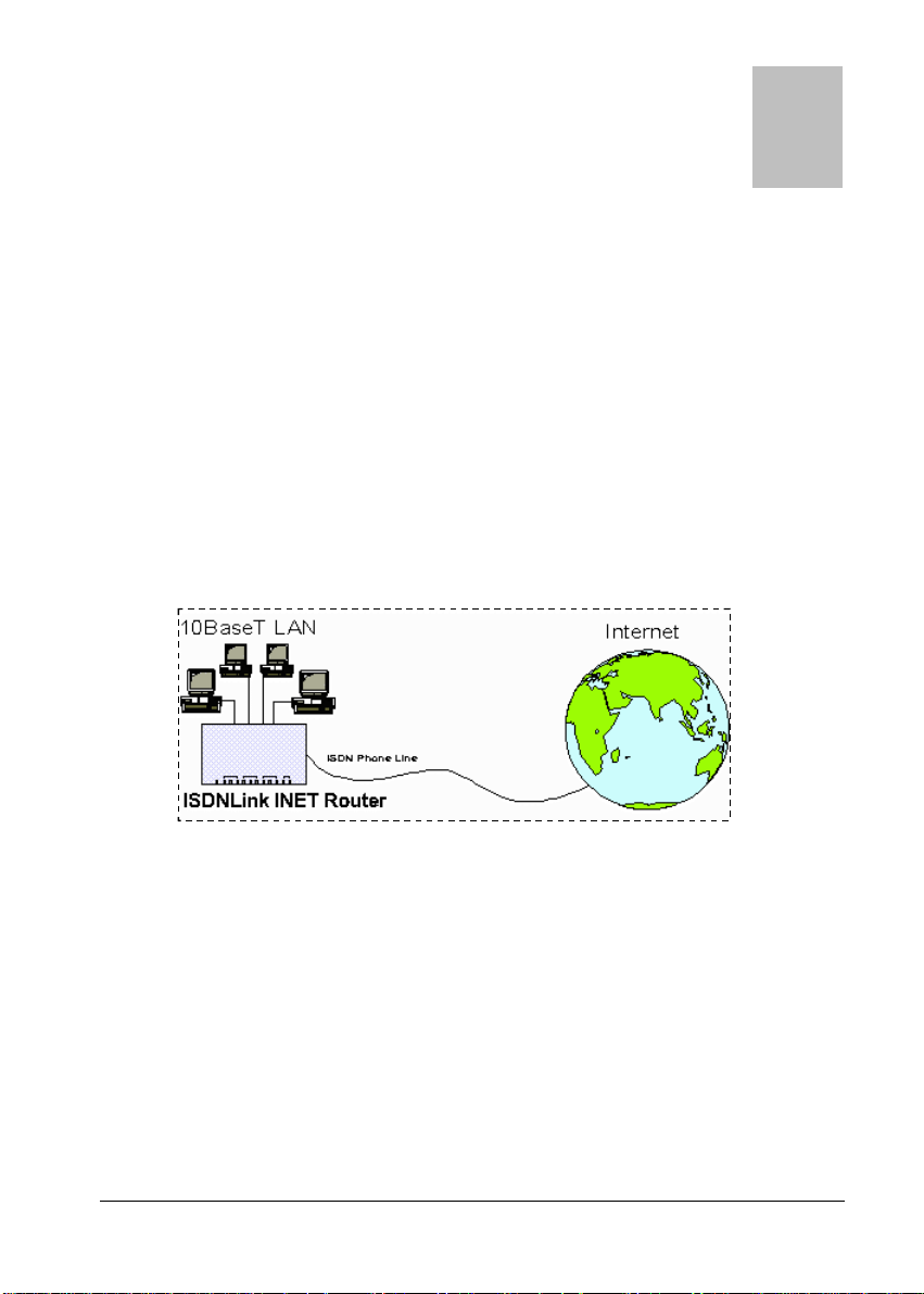
ongratulations on the purchase of your new Internet Router. The Internet
Router allows multiple SOHO (Small Office Home Office) users to share a single
Internet user account over an ISDN phone link. It provides the cost-effective
solution of giving users of your network easy access to the vast resources available
on the Internet.
Figure 1: Office to Internet
All of the Internet Router models include a built-in 4 port 10BaseT hub, allowing
you to easily create a peer-to-peer network.
Internet Router INET-830 and INET-850 include two (2) analog a/b ports, allowing
you to connect the analog a/b (POTS) telephone, answering machine, or fax.
For added versatility, the Internet Router INET-830 and INET-850 include a
printer port, allowing LAN users to share the attached printer.
1

Internet Router User Guide
Internet Router Features
The Internet Router incorporates many advanced features, carefully designed to
provided sophisticated functions while being easy to use.
LAN Features
Ø Built-in Hub. The built-in 4-port hub saves the cost and additional wiring of
a separate hub.
Ø Hassle-free LAN Installation. Just plug it in, whether or not you wish to
use the built-in hub.
Ø DHCP Server Support. Dynamic Host Configuration Protocol provides a
dynamic IP address to PCs and other devices upon request. The Internet
Router can act as a DHCP Server.
Ø Multi Segment LAN Support. If you have a Router, PCs on other LAN
segments can use the Internet Router to access the Internet and, on INET-830
and INET-850, share the printer.
Internet Access Features
Ø Shared Internet Account. All users on the LAN can share the same Internet
Account.
Ø Additional Bandwidth via Serial Port. If the ISDN link is insufficient, you
can connect a modem or ISDN TA to the serial port to provide increased
bandwidth.
Ø Dial-On-Demand & Auto-Disconnect. A connection is established to the
Internet as required, and automatically disconnected when no longer needed.
This reduces on-line charges to the minimum possible level.
Ø PPP Authentication. This is used to validate the log-on to your Internet
Service Provider.
2

About your Internet Router
ISDN Features
Ø Easy Configuration. No complex technical data or unintelligible prompts.
You’ll be finished in minutes!
Ø Intelligent B Channel Utilization. Internet access will automatically switch
between 1 or 2 B channels, depending on the data traffic volume.
Ø Outgoing call ID. The Internet Router supports Outgoing call ID for both
MSN (Multiple Subscriber Numbering) and SAD (Sub Address).
Ø Analog Ports. Two (2) analog a/b ports are provided, to allow connection of
your existing analog telephone, answering machine, or fax. (for INET-820
and INET-850)
Ø Analog Call Priority. If both B channels are in use, one channel will be
disconnected when an incoming voice call is detected, or you wish to make an
outgoing voice call. (for INET-820 and INET-850)
Printer Sharing Features (for INET-830 and INET-850)
Ø LAN Printer Sharing. Users on the LAN can share the printer attached to
the Internet Router. All they need to do is install and configure the supplied
software on their PC.
Ø Easy installation & configuration. The "Internet Router Printer Port"
software required for printer sharing installs quickly and requires minimal
configuration.
Configuration & Management
Ø Easy Setup. Use your WEB browser from anywhere on the LAN for configu-
ration.
Ø Remote Management. The Internet Router can be managed, if required,
from a workstation anywhere on the LAN, using a WEB browser.
3

Internet Router User Guide
Ø Remote Monitoring. Internet access via the ISDN link, or serial port usage,
can be monitored from any workstation on the LAN.
Printer status can be checked using the standard Windows printer features.
Security Features
Ø Configuration Data. Optional password protection is provided to prevent
unauthorized users from modifying the configuration.
Ø Firewall Protection. All incoming data packets are monitored and all
incoming server requests are filtered, thus protecting your network from malicious attacks from external sources.
4

About your Internet Router
Firewall Protection
The firewall protection provided by the Internet Router is an intrinsic side effect
of IP sharing. All users on the LAN share a single external IP address. From
the external viewpoint, there is no network, only a single device.
For internal users, the Internet Router acts as a “transparent proxy server”,
translating the multiple internal IP addresses into a single external IP address.
For external requests, any attempt to connect to local resources are blocked. The
Internet Router will not “reverse translate” from a global IP address to a local IP
address.
This type of “natural” firewall provides an impregnable barrier against malicious
attacks.
5

Internet Router User Guide
Requirements
< PCs with Ethernet Network cards and 10BaseT connectors
< 10BaseT network cable(s), with RJ45 connectors. One of these cables can be
used to connect the ISDN phone line.
< Software drivers for the network cards installed on each PC.
< ISDN phone line, fitted with a NT-1 (Network Termination 1) termination and
RJ45 sockets for S/T connection.
< Internet Access account with a local ISP (Internet Service Provider).
< For Printer Sharing, PCs must be running one of the following operating
systems:
= Windows 95 or 98
= Windows NT 3.51, NT4.0
Package Contents
The following items should be included:
< The Internet Router Unit.
< Power Adapter.
< ISDN RJ-45 connection cable (5M).
< One (1) 1.44M floppy disk (or CD diskette), containing the printer port redi-
rector software.
< This User’s Manual.
If any of the above items are damaged or missing, please contact your dealer as
soon as possible.
6

About your Internet Router
Internet Router INET-810 and INET-830
PWR ERR LNK SD RD CDCOL LK B1 B2 T1 T2
LAN WAN TELISDN
EA B C D
Figure 2: INET-810 and INET-830
Figure 3: Rear Panel INET-810 and INET-830
7

Internet Router User Guide
Internet Router INET-820
PWR ERR LNK SD RD CDCOL LK B1 B2 T1 T2
LAN WAN TELISDN
Figure 4: INET-820
Rear Panel
ON/OFF
POWER UPLINK
1
1 2 3
2
3
4
4
Figure 5: Rear Panel INET-820
EA B C D
7
8 9
1 2ON3 4 5
WAN
5
ISDN TEL1 TEL2
6
8

Internet Router INET-850
Printer Port
About your Internet Router
PWR ERR LNK SD RD C DCOL LK B1 B2 T1 T2
LAN WAN TELISDN
Figure 6: INET-850
Rear Panel
ON/OFF
POWER UPLINK
1
1 2 3
2
3
4
4
Figure 7: Rear Panel INET-850
EA B C D
7
8 9
1 2ON3 4 5
WAN
5
ISDN TEL1 TEL2
6
9

Internet Router User Guide
LED Indicators
A Power
B LAN ERR –Indicates an error, but normally lights up briefly
C WAN SD – Flashes when data is sent through the serial (WAN)
D ISDN LK – ON while the ISDN connection is being used.
E TEL T1 – ON while analog port 1 is in use.
Lights when power is ON.
during power On. See the following table for more information.
LNK – Traffic is being transmitted or received on the
LAN.
This LED also works in conjunction with the ERR LED to
indicate errors. See the following table for more information.
COL – Packet collision. Collisions are normal; only if this
light is on most of the time is there a problem.
port.
RD – Flashes when data is received through the serial
(WAN) port.
CD – Carrier Detect. This is ON when the WAN (serial
port) connection is active.
B1 – Flash while the 1st B channel is in use.
B2 – Flash while the 2nd B channel is in use.
T2 – ON while analog port 2 is in use.
10
All 12 LEDs will light briefly on power on. This is normal.

About your Internet Router
Link/Error LEDs
Operation of the Link and Error LEDs is as follows:
Link Error Description
On On During power On, both LEDs should light, then the
error LED should go off.
If both LEDs stay on, there is a hardware problem.
On Off Idle
Flashing Off Normal Operation – transmitting or receiving data
via the LAN.
Rapid intermittent
flashing of each LED
Hardware error, as detailed below.
Error Conditions (G = Green, R = Red)
G-R (repeated) RAM error
G-G-R-R (twice, repeated) Flash RAM error
G-G-G-R-R-R (3 times, repeated) Timer error
G-G-G-G-R-R-R–R
(4 times, repeated)
G-G-G-G-G-R-R-R-R-R
(5 times, repeated)
G-G-G-G-G-G-R-R-R-R-R-R
(6 times, repeated)
Serial port error
LAN port error
ISDN link error
11

Internet Router User Guide
Rear Panel Connectors & Switches
1 Power switch
2 Power port
3 Hub LEDs
4 10BaseT ports
5 10BaseT
uplink port
6 WAN port
7 DIP switches
8 ISDN port
9 Analog tele-
phone ports
Electrical switch. IN is ON.
Connect the power adapter here. Use only the unit
provided.
10BaseT port indicators – flash when the hub port
is in use.
Connect 10BaseT cabling here, and the other end
to the PC.
If using both the built-in hub and another hub, use
this port to connect to the other hub.
When this port is in use, port 4 can NOT be used.
Serial port. If using an external modem, connect it
here. See Chapter 9 – Serial Port for further
information.
See the following section.
Use a cable with RJ45 connectors to link this port
to the S/T interface on the NT-1.
If using analog devices, connect them here. See
Chapter 8 – Analog Ports for configuration
details.
12

About your Internet Router
DIP Switches
Settings Description
SW1 SW2 SW3 SW4 SW5
Off Off Normal operation
Off On Disable DHCP server
On Off Restore defaults
Reserved1Reserved1Reserved
1
3
2
On On
1
Do not change the default values unless advised to do so by technical support staff.
2
This will override the setting on the DHCP Server screen.
3
Restores the default IP address (192.168.0.1), and clears the password, provided
Reserved
the following procedure is carried out.
If you merely leave the DIP switches is this position, the Internet Router will
function normally.
Restore Default IP Address
and Clear Password
If the Internet Router's IP Address or password is lost, the following procedure can
be used to recover from this situation.
1. Turn the power to the Internet Router OFF.
2. Set DIP switch 1 ON, and DIP switch 2 OFF.
3. Turn the power to the Internet Router ON.
4. Operate DIP switch 1 in the following sequence (you have 15 seconds to
complete the sequence):
= OFF, ON, OFF
5. The Internet Router will now reset, and the Red LED will flash. The following
changes will have been made. (Other configuration data is unchanged.)
= IP Address set to its default value of 192.168.0.1
= Network Mask set to 255.255.255.0
= The password cleared (no password).
13

Internet Router User Guide
6. You can now connect to the Internet Router and make any configuration
changes required.
14

Chapter 2
2
Setup:
Internet Access
This Chapter explains how to install and configure the Internet
Router for Internet Access.
Overview
Setup involves:
< Hardware Installation
< Internet Router configuration
< PC configuration
Software installation is required only for printer sharing. Refer to Chapter 3 –
Printer Sharing for details.
Hardware Installation
1. Connect Network Cables
For each PC, connect one end of a 10BaseT network cable to the Internet
Router’s RJ-45 socket (port1 to 4) and the other end into the RJ45 socket on
the PC. Cable length should not exceed 100 meters (yards).
If connecting the Internet Router to another hub, connect
the "Uplink" port on the Internet Router to a normal port on
the other hub. Note that when the “Uplink” port is in use,
port 4 can NOT be used.
15

Internet Router User Guide
3. Connect ISDN Phone Line
Using a cable fitted with RJ45 plugs, connect the ISDN port on the Internet Router
to the S/T interface on the NT-1 (Network Termination 1) ISDN terminator.
4. Connect Printer (INET-830 and INET-850 only)
Using a standard printer cable, connect the printer to the printer port on the
Internet Router.
5. Power On and Check the LEDs
Connect the supplied power adapter to the Internet Router and press the ON/OFF
switch on the back of the Internet Router. (In is ON.) When the Internet Router is
powered On, all LEDs should blink, then, except for the PWR LED, go off.
If the ERR LED stays on, or both the ERR and LNK LEDs continue to blink, there
is a hardware problem.
For more information on the LEDs, refer to LED Indicators on page 10 and
Link/Error LEDs on page 11.
Warning!
Only use the power adapter provided. Using a different one
may cause hardware damage.
Internet Router Configuration
The Internet Router contains a HTTP server. This enables you configure it using
your Web Browser. Most Browsers should work, provided they support HTML
tables and forms.
Preparation
Ensure your PC is using the TCP/IP protocol, and configure it to use the Internet
Router’s DHCP server, as follows:
DHCP Client Setup - Windows 95/98
1. Select the Network Neighborhood icon on the desktop, then Properties. You
will see a screen like the one below:
16

Setup: Internet Access
Figure 8: Network Configuration tab
2. If a line like the one highlighted ("TCP/IP -> Network Card”) is not listed,
select Add-Protocol-Microsoft-TCP/IP-OK to add it.
3. Select Properties for the “TCP/IP -> Network card” entry. You will see a
screen like the following:
Figure 9: TCP/IP Properties - DHCP
4. On the IP Address tab, click the radio button for “Obtain an IP address auto-
matically”, as above, then reboot. Your PC will obtain an IP Address from the
Internet Router.
If your LAN already has a DCHP Server:
< Set DIP switch 2 ON to disable the DHCP server in the Internet Router.
< Enter a fixed IP Address on your PC, as shown below.
17

Internet Router User Guide
Figure 10: TCP/IP Properties – Fixed IP Address
Connecting to the Internet Router
1. Start your WEB browser
2. In the Address box, enter "HTTP://" and the IP Address of the Internet Router.
For example (using default IP Address):
HTTP://192.168.0.1
3. You will see the Home screen. Select Basic Setup.
If you can't connect, check:
< The Internet Router is properly installed, LAN connec-
tions are OK, and it is powered ON.
< Your PC and the Internet Router are on the same
network segment. (If there is no router, this must be the
case.)
< If another PC or device is using the same IP address
(192.168.0.1) as the Internet Router, turn the other device OFF until you assign a new address to the Internet
Router.
< That your PC has a compatible IP address (either static
or obtained as a DHCP client)
= In the Windows 95/98/NT “Run” dialog, enter:
winipcfg
= Ensure that the drop-down list is set to your Network
18

Setup: Internet Access
card. The current IP Address and Network mask (Subnet Mask) will be displayed.
= The IP address must be in the range 192.168.0.2 to
192.168.0.254, and the Network mask must be
255.255.255.0
< Ensure that your PC is NOT configured to use a “Proxy
Server”. In Internet Explorer, this can be checked using
View – Internet Options - Connection. In Netscape,
check Options – Network Preferences – Proxies.
Password
If a password has been set for the Internet Router, you will be prompted for the
password, as shown below. (If no password has been set, you will not see this dialog
box.)
Figure 11: Password Dialog
Leave the "User Name" blank, and enter the password you assigned to the Internet
Router.
Navigation & Data Input
< Use the navigation bar on the left of the screen, and the "Back" button on your
Browser, to move about.
< You must save your data before changing screens, or any data you have entered
will be lost.
19

Internet Router User Guide
Basic Setup Screen
Select the Basic Setup link from the navigation bar. You will see a screen like the
example below.
20
Figure 12: Basic Setup Screen
 Loading...