

iScan VP50 Owner's Manual
H I G H - D E F I N I T I O N V I D E O P R O C E S S O R & H U B
O W N E R ’ S M A N U A L

DVDO BY ANCHOR BAY TECHNOLOGIES, INC.
LIMITED WARRANTY
WARRANTY VALID ONLY IN THE U.S.A.
WARRANTY
DVDO by Anchor Bay Technologies, Inc. (DVDO) warrants that products distributed in the U.S.A. that fail to function properly under normal use due to a
manufacturing defect when installed and operated according to the owner’s manual enclosed with the unit will be repaired or replaced with a unit of comparable
value, at the option of DVDO, without charge to you for parts or actual repair work. Parts supplied under this warranty may be new or rebuilt at the option
of DVDO.
THIS LIMITED WARRANTY APPLIES TO THE ORIGINAL OWNER OF THIS DVDO PRODUCT DURING THE WARRANTY PERIOD
PROVIDED THE PRODUCT WAS PURCHASED FROM AN AUTHORIZED DVDO DISTRIBUTOR/DEALER IN THE U.S.A. YOU WILL BE
REQUIRED TO PROVIDE A SALES RECEIPT OR OTHER VALID PROOF OF PURCHASE SHOWING THE DATE OF ORIGINAL PURCHASE.
IN THE EVENT SERVICE IS REQUIRED, THE PRODUCT MUST BE DELIVERED WITHIN THE WARRANTY PERIOD, TRANSPORTATION
PREPAID, ONLY FROM WITHIN THE U.S.A. AS EXPLAINED IN THIS DOCUMENT. YOU WILL BE RESPONSIBLE FOR REMOVAL AND
INSTALLATION OF THE PRODUCT. DVDO WILL PAY TO RETURN THE REPAIRED OR REPLACEMENT PRODUCT TO YOU WITHIN THE U.S.A.
PRODUCT WARRANTY PERIOD
Parts Labor
iScan Video Processors .................................................................................................................... 1 Year 1 Year
Shorter periods may apply to some products. Please refer to the limited warranty document enclosed with your specic product for a denitive statement of the warranty period.
The warranty period for retail customers who rent the product commences upon the date product is rst put into use (a) during the rental period or (b) retail sale, whichever occurs rst.
WHAT IS NOT COVERED
IF THIS PRODUCT WAS PURCHASED FROM AN UNAUTHORIZED DEALER OR DISTRIBUTOR, THERE ARE NO WARRANTIES, EXPRESS OR
IMPLIED, INCLUDING THE IMPLIED WARRANTY OF MERCHANTABILITY AND THE IMPLIED WARRANTY OF FITNESS FOR A PARTICULAR
PURPOSE AND THIS PRODUCT IS SOLD STRICTLY “AS IS” AND “WITH ALL FAULTS”.
DVDO SHALL NOT BE LIABLE FOR ANY CONSEQUENTIAL AND/OR INCIDENTAL DAMAGES.
THIS WARRANTY DOES NOT APPLY IF THE PRODUCT HAS BEEN SUBJECTED TO POWER IN EXCESS OF ITS PUBLISHED POWER RATING.
THIS WARRANTY DOES NOT COVER THE CABINET OR ANY APPEARANCE ITEM, ANY DAMAGE TO RECORDING TAPES OR DISCS, TELEVISION
OR DISPLAY SCREENS DAMAGED BY STATIC, NON-MOVING, IMAGES APPLIED FOR LENGTHY PERIODS (BURN-IN), ANY DAMAGE TO THE
PRODUCT RESULTING FROM ALTERATIONS, MODIFICATIONS NOT AUTHORIZED IN WRITING BY DVDO, ACCIDENT, MISUSE OR ABUSE,
DAMAGE DUE TO LIGHTNING OR TO POWER SURGES, SUBSEQUENT DAMAGE FROM LEAKING, DAMAGE FROM INOPERATIVE BATTERIES, OR
THE USE OF BATTERIES NOT CONFORMING TO THOSE SPECIFIED IN THE OWNER’S MANUAL.
THIS WARRANTY DOES NOT COVER THE COST OF PARTS OR LABOR WHICH WOULD BE OTHERWISE PROVIDED WITHOUT CHARGE UNDER
THIS WARRANTY OBTAINED FROM ANY SOURCE OTHER THAN A DVDO AUTHORIZED SERVICE COMPANY OR OTHER DESIGNATED LOCATION.
THIS WARRANTY DOES NOT COVER DEFECTS OR DAMAGE CAUSED BY THE USE OF UNAUTHORIZED PARTS OR LABOR OR FROM IMPROPER
MAINTENANCE.
ALTERED, DEFACED, OR REMOVED SERIAL NUMBERS VOID THIS ENTIRE WARRANTY.
NO OTHER WARRANTIES
DVDO LIMITS ITS OBLIGATIONS UNDER ANY IMPLIED WARRANTIES INCLUDING, BUT NOT LIMITED TO, THE IMPLIED WARRANTIES OF
MERCHANTABILITY AND FITNESS FOR A PARTICULAR PURPOSE, TO A PERIOD NOT TO EXCEED THE WARRANTY PERIOD. NO WARRANTIES SHALL
APPLY AFTER THE WARRANTY PERIOD. SOME STATES DO NOT ALLOW LIMITATIONS ON HOW LONG AN IMPLIED WARRANTY LASTS AND SOME
STATES DO NOT ALLOW THE EXCLUSIONS OR LIMITATIONS OF INCIDENTAL OR CONSEQUENTIAL DAMAGES, SO THE ABOVE LIMITATIONS OR
EXCLUSIONS MAY NOT APPLY TO YOU. THIS WARRANTY GIVES YOU SPECIFIC LEGAL RIGHTS AND YOU MAY HAVE OTHER RIGHTS WHICH MAY
VARY FROM STATE TO STATE.
TO OBTAIN SERVICE
DVDO has appointed a number of Authorized Service Companies throughout the U.S.A. should your product require service. To receive warranty service you
need to present your sales receipt or, if rented, your rental contract showing place and date of original owner’s transaction. If shipping the unit you will need
to package it carefully and send it, transportation prepaid by a traceable, insured method, to the Authorized Service Company. Package the product using
adequate padding material to prevent damage in transit. The original container is ideal for this purpose. Include your name, address and telephone number
where you can be reached during business hours.
On all complaints and concerns in the USA call Customer Support at 1-866-423-3836.
For hook-up and operation of your unit or to locate an Authorized Service Company, please call or write:
TECHNICAL SUPPORT DEPARTMENT
DVDO BY ANCHOR BAY TECHNOLOGIES, INC
300 Orchard City Drive, MS 131
CAMPBELL, CALIFORNIA 95008
1-866-423-3836
http://www.DVDO.com
.
DISPUTE RESOLUTION
Following our response to any initial request to Customer Support, should a dispute arise between you and DVDO, DVDO makes available its Complaint
Resolution Program to resolve the dispute. The Complaint Resolution Program is available to you without charge. You are required to use the Complaint
Resolution Program before you exercise any rights under, or seek any remedies, created by Title I of the Magnuson-Moss Warranty-Federal Trade Commission
Improvement Act, 15 U.S.C. 2301 et seq.
To use the Complaint Resolution Program call 1-866-423-3836 and explain to the customer service representative the problem you are experiencing, steps
you have taken to have the product repaired during the warranty period and the name of the authorized Distributor/Dealer from whom the DVDO product
was purchased. After the complaint has been explained to the representative, a resolution number will be issued. Within 40 days of receiving your complaint,
DVDO will investigate the dispute and will either:
(1) respond to your complaint in writing informing you what action DVDO will take, and in what time period, to resolve the dispute; or (2) respond to your
complaint in writing informing you why it will not take any action.
RECORD THE PLACE AND DATE OF PURCHASE FOR FUTURE REFERENCE
Model No. ____________________________________________ Serial No. ___________________________________________ Purchase Date _______________________
Purchased From ______________________________________________________________________________________________________________
KEEP THIS INFORMATION AND YOUR SALES RECEIPT IN A SAFE PLACE

T A B L E O F C O N T E NT S
S E C T I O N 1 – G E T T I N G S TA R T E D 2
Introduction 2
Document Conventions and Menu Navigation 2
Remote Control Overview 3
Remote Control Battery Installation 4
Unpacking and Inspection 4
Display Compatibility Requirements 5
Installation Guidelines 6
S E C T I O N 2 – B A S I C OP E R A T I O N 7
Front Panel Overview 7
Rear Panel Overview 7
Video Inputs 8
Video Outputs 8
Audio Inputs 8
Audio Outputs 9
Info Screen 9
Power Supply Input 9
S E C T I O N 3 – S E T U P 10
Initial Set-Up 10
STEP 1 - Power Up 10
STEP 2 - Connect the iScan VP50 to your system 10
STEP 3 - Connecting Your Sources to the iScan VP50 11
VCR/LD Player/DVR 11
DVD Player/DVD Recorder 12
HD-STB/DVR, HD-DVD, Blu-ray Disc or DVHS 13
Game Console 13
PC 14
Audio Operation 14
1

i S C A N V P 5 0
S E C T I O N 4 – M E N U O P T I O N S 15
Input Select 15
Input Aspect Ratio Control 15
Zoom 17
Pan 17
Borders 17
Presets 18
Input Adjust Control 19
Deinterlacing 19
Overscan 20
Line Offset 20
Color Space 20
Input Level 20
VCR Mode 20
HDMICong. 20
Auto Input Priority Selection 21
Audio Input 21
AV Lip Sync™ 21
Picture Controls 21
Brightness 21
Contrast 22
Saturation 22
Hue 22
Sharpness 22
Y/C Delay 22
Chroma Filter (Auto CUE-C™) 22
Conguration 22
Test Patterns 22
Auto Standby 23
LED Brightness 23
User Mode 23
Serial Port Rate 23
Factory Default 23
Software Update 24
Information 24

T A B L E O F C O N T E N T S
Output Setup 25
Analog/Digital 25
Output Format 25
Output Aspect Ratio Control 25
Sync Type 27
Color Space 27
Output Level 27
Framerate Conversion 27
Border Level 29
Gamma Correction 29
HDCP Mode 29
DisplayProles 29
S E C T I O N 5 – A P P E N D I X 31
Non-Volatile Memory Settings 31
System Settings 31
Input/Format Settings 31
Setting up an iScan VP50 Using the Internal Test Patterns
and the VRS Optimization and Evaluation DVD 33
Determining the Correct Output Resolution for Your Display 33
Initial Setup of the iScan to Your Display 34
Display Calibration 36
Source Calibration 37
Record Your Settings 38
Test Pattern Descriptions 38
Troubleshooting 40
Complete Menu Tree 41
Index 48


S E C T I O N 1 – G E T T I N G S TA R T E D
Introduction
Thank you for purchasing the DVDO iScan VP50 Video Processor, brought to you by Anchor Bay
Technologies, Inc. We are especially pleased to bring you ABT’s new VRS Precision DeinterIac-
ing for both high denition and standard denition content along with ABT’s proven VRS Precision Video Scaling II technology. These technologies enable precision upconversion of standard
and high denition (480i/p, 576i/p, 720p or 1080i/p) video sources and content to the native or
optimum resolution of your display. Available output resolutions span from VGA up to 1080p,
including the standard HDTV resolutions of 720p and 1080i.
In addition to our own award winning video processing technologies, the iScan VP50 also offers a
host of other innovative features, including:
• 4 HDMI (High Denition Multimedia Interface) Inputs and 1 HDMI Output
• Analog Input and Output, using BNC-style Connectors
• Precision AV LipSync™
• AutoCUE-C™ - Automatic Chroma Upsampling Error Correction
• RightRate™ - Fully Programmable Framerate Conversion
• Precision Gamma Correction™
• Flexible Digital and Analog Audio Switching
• Timebase Correction
• Input and Output Aspect Ratio Controls
• Flexible Zoom and Pan Controls
• SDI Input Capability (optional, DVDO P/N SDI-601A)
This Owner’s Manual can help you set up your new iScan VP50, and give you the information to
properly set it up with your sources and display. It can also show you how to properly connect it
and use it with the other components in your system.
Document Conventions and Menu Navigation
In this Owner’s Manual, text that is in ‘quotes’ refers to an item in the iScan VP50’s on screen
display (OSD). For example, if the user were asked to access the ‘Deinterlacing’ menu on the
VP50, the word deinterlacing is in quotes so that the user knows what to look for in the OSD.
Text that is bold refers to a button on the remote control of the VP50. For example an instruction that says to ‘press u’ is telling the user to press the right navigational button on the remote
control (or alternatively, the front panel). Text that is in italics refers to instructions where
information can be found elsewhere. For example, you may be referred to another section of the
manual or to a specic page on the DVDO website.
In this Owner’s Manual, an action that requires navigating the menu system of the iScan VP50 is
referred to in the following abbreviated form:
2
Picture Control _ Contrast _5
INPU T SELEC T
STANDBY
POWER
INPUT
ADJUST
CONFIG
PICTURE
CONTROL
OUTPUT
SETUP
MENU EXIT
16:94:3
AUTO
VIDEO 1S-VIDEO 1COMP 1HDMI 2
VIDEO 2S-VIDEO 2COMP 2HDMI 3
ENTE R
HDMI 4
BORDER CROP
INFO
CURTAIN
MEMO RIES
RGBHV
HDMI 1 SDI
ASPECT
ZOOM PAN
ON/OFF
DISPLAY
PROFILES
VIEWING
MODES
INPUT
ASPECT
RATIO
TEST PATTERN
ENTE R
Standby
Info
Curtain
Output Setup
Configuration
Picture Control
Input Adjust
Menu
Border
Zoom
Input Select
(HDMI 1, HDMI 2, HDMI 3, HDMI 4,
Component 1, Component 2,
RGBHV/Component,
S-Video 1, S-Video 2,
Video 1, Video 2, AUTO)
Aspect
Exit
Crop
Pan
Power
Input Aspect
Ratio
Viewing Modes
Display Profiles
4:3
16:9
Test Patterns
(Left, On/Off, Right)
4
23
29
*
*
18
4
17
16
16
4
9
4
25
23
21
19
4
4
17
15
17
15
In this example, the instructions are to adjust the ‘Contrast’ to a value of ‘5’. To do this, press Picture
Control and then press q once, highlighting ‘Contrast’ in the On Screen Display (OSD) or if you are
looking at the front panel display (FPD) you will see ‘Picture Control’ on the top line and ‘Contrast’ on
the bottom line. This is abbreviated as ‘Picture Control / Contrast’. Next press u to adjust the setting
and then press p until the value is ‘5’. Finally, press Exit.
The t , u,q, and p symbols refer to the navigational keys on the remote control and the front panel
of the iScan.
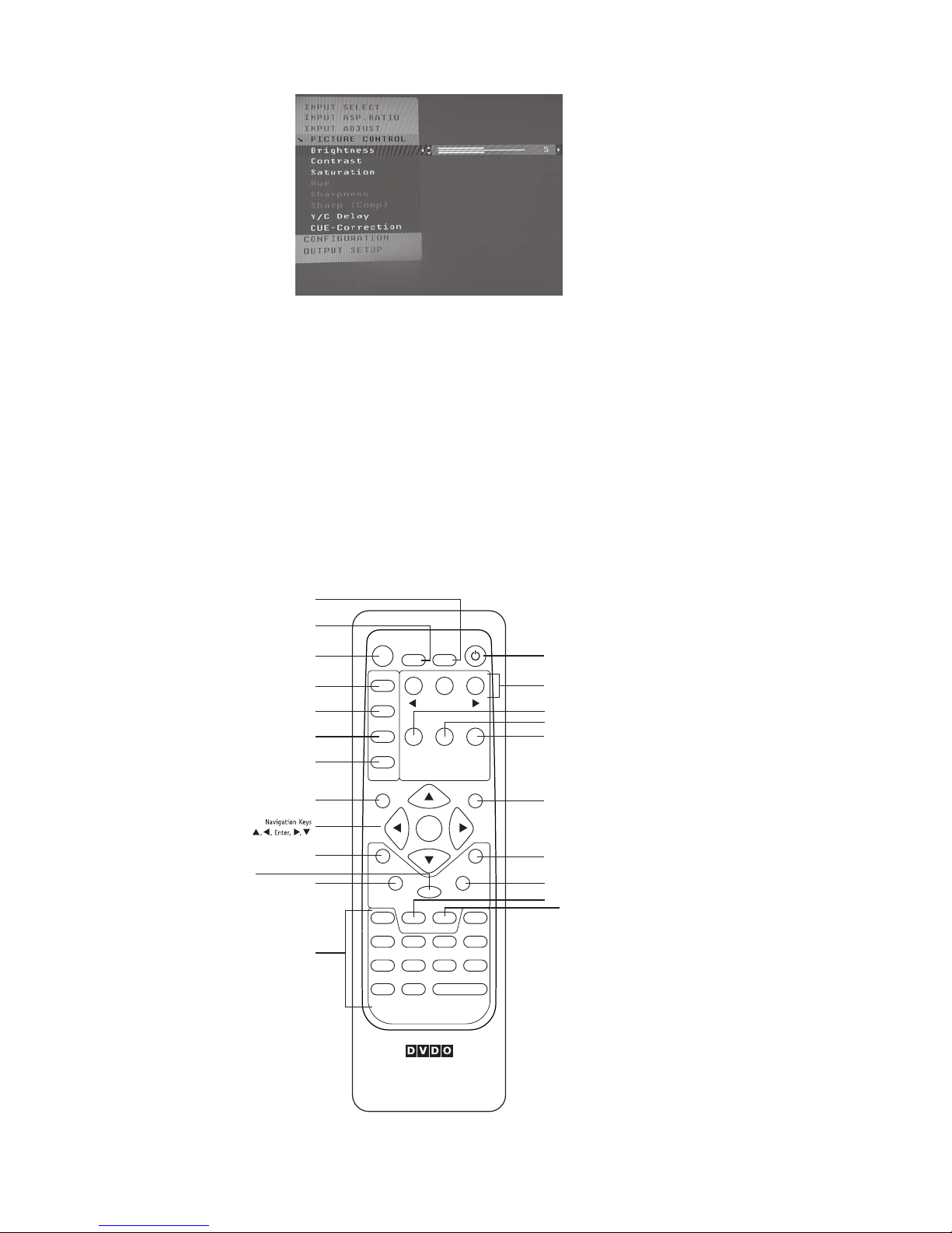
Remote Control Overview
For additional information about the functions of these buttons, turn to the pages given in parentheses
( ).
An asterisk (*) indicates this feature will be implemented in future software.
3

Power/Standby Buttons
The iScan VP50 remote has a Power and a Standby button. The Power button always turns the iScan
VP50 on and the Standby button always put the unit into Standby mode.
Curtain Button
The iScan VP50 remote has a Curtain button which allows you to close a ‘curtain’ over the image.
This feature is especially useful when an image is paused on a display susceptible to burn-in, like a
plasma or CRT-based display.
Remote Control Battery Installation
The remote control uses two AAA batteries, which should be replaced as needed. Two AAA batteries
are included.
To install the remote control batteries:
1. Locate the battery compartment on the back of the remote control.
2. Remove the cover from the back. To do this, press the tab attached to the cover
and pull the cover with the guide on the back of the remote control.
3. Remove the old batteries (if applicable).
4. Insert two new AAA batteries in the compartment as shown on the inside of the battery
compartment. Make sure the batteries are correctly inserted, observing the proper polarity.
5. After installation, replace the cover and dispose of the old batteries (if applicable).
Menu Navigation
You can control the iScan VP50 as follows:
• From the front panel controls
• From the iScan VP50 remote control
• From a programmed universal remote control
• Using the serial connection on the back panel
The menu navigation controls on the remote control are duplicated on the front panel of the iScan VP50.
To navigate the menu:
1. Press the
2. Use the directional buttons (t ,p,q, u) to highlight the parameter you want to change.
3. Press the Enter or u button to select the parameter and the p and q buttons to change
the chosen parameter. Press the t button to stop adjusting a parameter and to return
to navigating the OSD.
4. Press the Exit button to exit out of the menu/OSD
Menu button.
Unpacking and Inspection
Please verify that your iScan VP50 carton contains the following items:
• iScan VP50 Video Processor
• Universal 6V@7A AC-to-DC Power Converter
• US IEC Power Cord (International Customers, consult your local authorized DVDO reseller)
• Remote Control
• iScan VP50 Owner’s Manual
• iScan VP50 Quick Start Guide
4
• Serial Cable for Software Updates and Automation (1:1)
•
VRS Optimization & Evaluation DVD
• DVDO Software CD
If you are missing any items, please contact your dealer or the DVDO Support Team.
The iScan VP50 uses BNC-style analog connectors and an HDMI digital connector to provide video
output signals. You must purchase a cable or adapters to connect this output to your display. Different
displays have different input connectors, so check your display specications to ensure compatibility.
Both input and output cables can be supplied by your Authorized DVDO Reseller. To nd your nearest
Authorized DVDO Reseller, go to www.dvdo.com/res/index.html. There are also a wide selection
of cables and adapters available on our website at www.dvdo.com/pro/pro_acc.html.
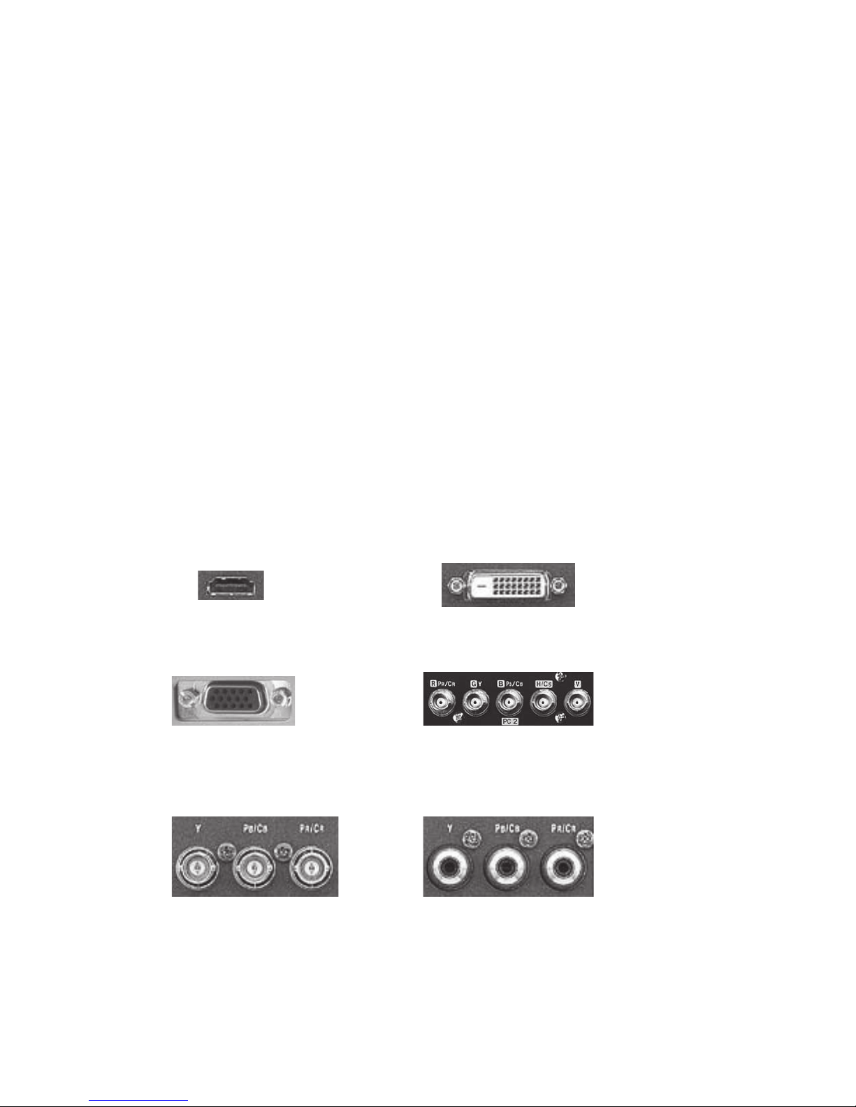
Display Compatibility Requirements
DVDO iScan video processing products are compatible with a wide range of displays. These include
digital TVs, projectors, and at panel displays, as well as other emerging technologies that can
support 480p or higher resolution video signals. To determine if your display is compatible with the
DVDO iScan VP50, look to see if it has one of the digital inputs listed below. If not, then your display
may only have analog High Denition inputs or it is probably limited to receiving a standard NTSC, PAL
or SECAM interlaced signal and will not function correctly with iScan VP50.
Digital Inputs
HDMI input DVI-D input
Analog Inputs
VGA HD-15 input 5 BNC RGBHV inputs
Component input that are not capable of accepting a 480p signal should be labeled ‘480i’
(NTSC) or ‘576i’ (PAL/SECAM).
Component input (YPbPr or YCbCr)
5

The following types of displays with digital video inputs should be compatible with the iScan
VP50 since a large majority of them can support higher resolution signals:
• Plasma displays
• LCD-based at panel and front & rear projection displays
• DLP-based front & rear projection displays
• LCoS-based front & rear projection displays (D-ILA™ & SXRD™ included)
• CRT-based Direct View and front and rear projection displays
Installation Guidelines
Take special care with the iScan VP50 installation to ensure optimal performance. Pay particular attention
to the bulleted items that begin below and to other precautions that appear throughout this guide.
Do...
• Install the iScan VP50 on a solid, at, level surface such as a table or shelf. You can
also install the iScan VP50 in a standard 19” equipment rack using an optional rack-mount
kit available from authorized DVDO resellers or directly from DVDO.
• Select a dry, well-ventilated location.
• Use only the included external power supply.
• Avoid excessive humidity, sudden temperature changes or temperature extremes.
• Use only accessories recommended by the manufacturer to avoid re, shock or
other hazards.
• Unplug your iScan VP before cleaning. Use a damp cloth for cleaning.
Don’t...
• Install the iScan VP50 on an unstable surface or one that is unable to support all four of its
feet, unless it is installed in an equipment rack.
• Stack the iScan VP50 directly above heat-producing equipment such as power ampliers or
other components that generate heat during use.
• Expose the iScan VP50 to a high temperatures, humidity, steam, smoke, dampness, or
excessive dust. Avoid installing the iScan VP50 near radiators and other heat producing
appliances.
• Install the iScan VP50 near unshielded TV or FM antennas, cable TV decoders, and other
RF-emitting devices that might cause interference.
• Place the iScan VP50 on a thick rug or carpet or cover the iScan VP50 with cloth. This might
prevent proper cooling.
• Attempt to service this unit. Instead, disconnect it and contact your Authorized DVDO
Reseller or contact Anchor Bay Technologies directly.
• Open or remove unit panels or make any adjustments not described in this manual.
Attempting to do so could expose you to dangerous electrical shock or other hazards.
It may also cause damage to your iScan VP50.
• Obstruct the front panel IR receiver window shown in “Remote Control Overview”.
• Do not attempt to use the remote control out of line of sight with the IR receiver. Doing so
will cause improper operation.
6
S E C T I O N 2 – B A S I C OP E R A T I O N
MENU
EXIT
Front Panel Display (FPD)
Adjustment Buttons
Up
On/Standby Left Down Right
Menu
Exit
IR Window
Status LED
HD MI
1 2 3 4
INPUT
OUTPUT
1
324
SERIA L PORT
ANALOG AU DIO INPUT
Y (G) Pb (B) Pr (R) H V
Y (G) Pb (B) Pr (R)
1
212
121
2
CO M PO NE NT
L R
AN A LO G VI D EO
OUTPUT
I
I
N
P
U
T
O
U
T
P
U
T
Component 1
(YPbPr or RGB)
Component 2
(YPbPr or RGB)
Power
Composite
Video 1
Composite
Video 2
Digital
Audio Out
(optical)
Digital
Audio Out
(coaxial)
Digital Audio
Inputs 1, 2
(optical)
Digital Audio
Inputs 3, 4
(coaxial)
Serial Port
S-Video 1
S-Video 2Sync 2
Sync 1
Analog Video
Output
HDMI Inputs
1, 2, 3, 4
HDMI Output
Analog Audio
Inputs L, R
DI G IT AL A UD I OS-VID EO VID EOSYNCPOWER
SDI Input
Analog Video
Input
INPUT
DC In
P
U
T
S
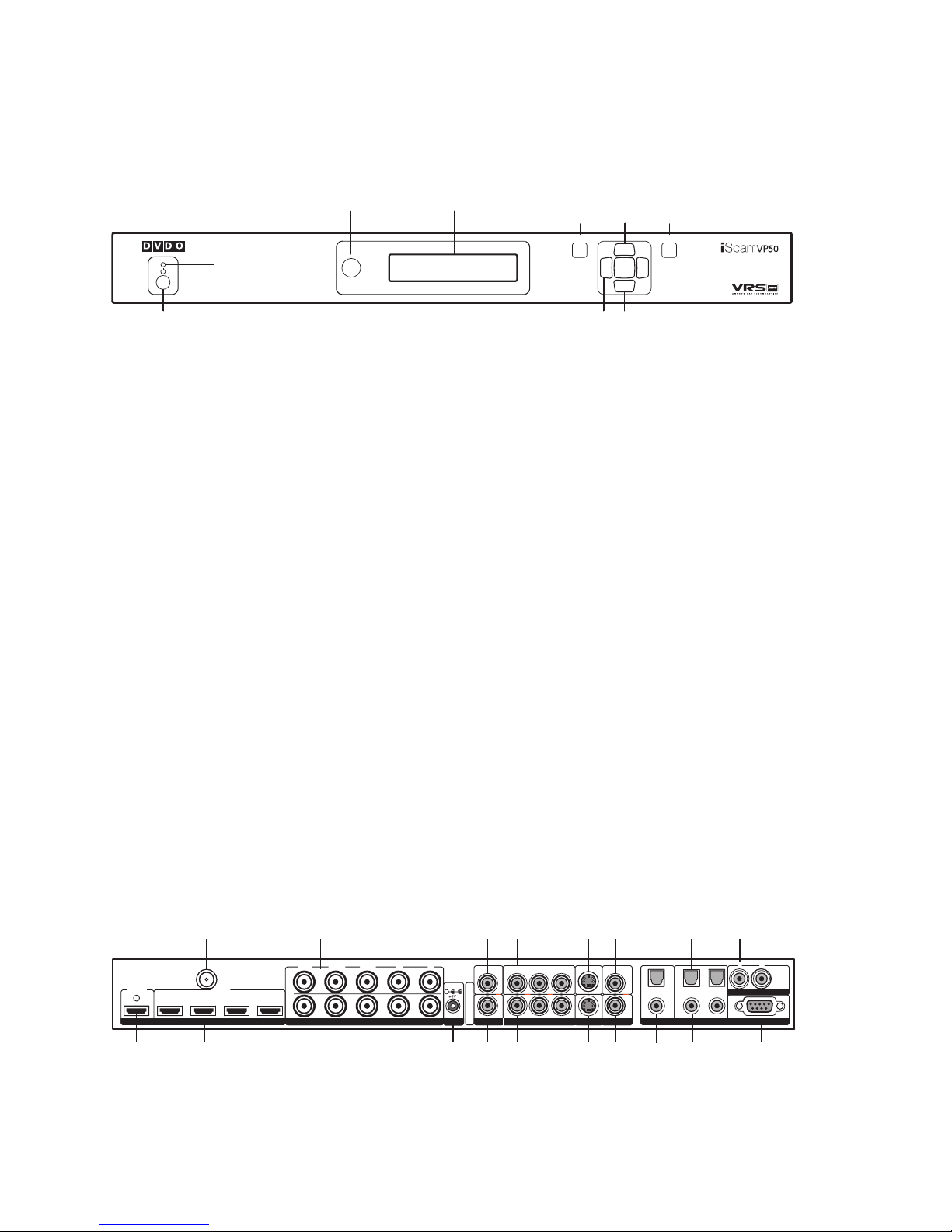
Front Panel Overview
Status LED – This displays the current state of the iScan VP50
Off = The unit is in standby mode
Red = No signal detected
Blue = The unit is processing the signal
Blinking Blue = There is a problem with HDCP authentication
Green = The unit detects an unsupported signal
On/Standby – This toggles unit power between On and Standby.
IR Window – This is where all IR commands are received by the iScan. Do not obstruct
this window.
7
Front Panel Display (FPD) – This is where all information from the on screen display (OSD) is duplicated to assist in the setup of your iScan.
NOTE: When navigating the OSD, the FPD always shows the current selection on the bottom line
and the menu/submenu item on the top line. When you change a value of a setting, the value is on
the bottom line and the title of the parameter is on the top line.
Navigation Keys – These keys are duplicated on the remote control and function exactly the
same.
NOTE: Switching Inputs using the Navigation keys – You can switch inputs on the front panel of
the iScan VP50 or using the remote using the navigation keys. To do this, press the p or q without
pressing the Menu button rst.
Rear Panel Overview

Video Inputs
The iScan VP50 has eleven (11) video inputs and an optional SD-SDI input available (P/N SDI601A). The inputs and the formats they support are as follows:
• Video 1 (NTSC, PAL, PAL-M and SECAM)
• Video 2 (NTSC, PAL, PAL-M and SECAM)
• S-Video 1 (NTSC, PAL, PAL-M and SECAM)
• S-Video 2 (NTSC, PAL, PAL-M and SECAM)
• Component/RGBS 1 (480i/p@60Hz, 576i/p@50Hz, 720p@50Hz, 720p@60Hz, 1080i@50Hz,
1080i@60Hz)
• Component/RGBS 2 (480i/p@60Hz, 576i/p@50Hz, 720p@50Hz, 720p@60Hz, 1080i@50Hz,
1080i@60Hz)
• RGBHV/Component (480p@60Hz, 576p@50Hz, 720p@50Hz, 720p@60Hz, 1080i@50Hz,
1080i@60Hz, VGA/SVGA/XGA/SXGA@60Hz
• HDMI 1 (480i/p, 576i/p, 720p@50Hz, 720p@60Hz, 1080i@50Hz, 1080i@60Hz, 1080p@50Hz,
1080p@60Hz, VGA/SVGA/XGA/SXGA@60Hz RGB 4:4:4/YCbCr 4:4:4/YCbCr 4:2:2)
• HDMI 2 (480i/p, 576i/p, 720p@50Hz, 720p@60Hz, 1080i@50Hz, 1080i@60Hz, 1080p@50Hz,
1080p@60Hz, VGA/SVGA/XGA/SXGA@60Hz RGB 4:4:4/YCbCr 4:4:4/YCbCr 4:2:2)
• HDMI 3 (480i/p, 576i/p, 720p@50Hz, 720p@60Hz, 1080i@50Hz, 1080i@60Hz, 1080p@50Hz,
1080p@60Hz, VGA/SVGA/XGA/SXGA@60Hz RGB 4:4:4/YCbCr 4:4:4/YCbCr 4:2:2)
• HDMI 4 (480i/p, 576i/p, 720p@50Hz, 720p@60Hz, 1080i@50Hz, 1080i@60Hz, 1080p@50Hz,
1080p@60Hz, VGA/SVGA/XGA/SXGA@60Hz RGB 4:4:4/YCbCr 4:4:4/YCbCr 4:2:2)
With the DVDO SDI Input Module installed, you will also be able to access the SDI input.
• SDI (480i@60Hz and 576i@50Hz YCbCr 4:2:2)
Video Outputs
The iScan VP50 has two video outputs, one analog and one digital. The analog output on the iScan
VP50 can output the following signal types:
• YPbPr (Component)
• RGBHV
• RGsB
• RGBS
The HDMI digital video output can output the following signal types:
• RGB 4:4:4 (8-bit, DVI standard)
• YCbCr 4:2:2 (10-bit)
• YCbCr 4:4:4 (8-bit)
To connect the iScan VP50 to a display that has a DVI input, use either an HDMI-to-DVI cable or
an adapter.
Audio Inputs
There are nine (9) audio inputs on the iScan VP50:
• Two (2) Optical Digital inputs
• Two (2) Coaxial Digital inputs
• One (1) Analog (L/R) input
• Four (4) HDMI inputs
While the digital and analog audio inputs can be assigned to any one of the video inputs, the HDMI
audio inputs are tied directly to the HDMI video signal connected on the same input.
8
The iScan VP50 accepts digital audio sourced from DVD players, satellite receivers, digital set top
boxes, HD-DVD players, BluRay players, game consoles, and other digital audio devices. These inputs
are compatible with most consumer digital audio formats, including CD-Audio (44.1kHz/16 bit LPCM),
Dolby Digital, and DTS. The coaxial digital audio inputs are compatible with any format with a sam-
pling frequency between 24kHz and 192kHz, and with a data word structure up to 24 bits in length.
The optical digital audio inputs are compatible with any format with a sampling frequency between
24kHz and 96kHz and with a data word structure up to 24 bits in length. The HDMI audio inputs are
compatible with HDMI 1.1 audio formats.
Audio Outputs
There are two discrete digital audio outputs, one coaxial and one optical. Both are active at the same
time, with the selected input audio stream. The HDMI output carries both audio and video.
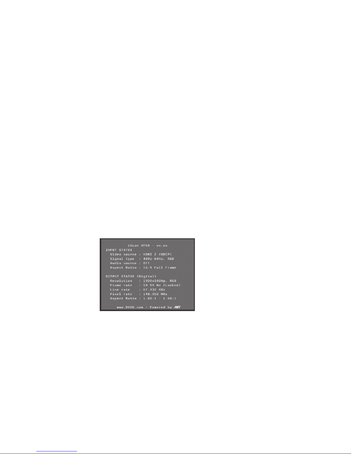
Info Screen
Press the Info button to display a window that shows information about the system including:
• Input Status
— Video Source
— Signal Type
— Audio Source
— Aspect Ratio (Frame AR/Active AR)
• Output Status
— Resolution
— Frame Rate
— Line Rate
— Aspect Ratio (Display AR/Screen AR)
This screen can be helpful during troubleshooting.
Power Supply Input
The iScan VP50 comes with a 6V@7A AC-to-DC converter power supply, which accepts 100-240 VAC
at 50/60Hz.
To attach power to the unit:
1. Attach the removable power cord to the external power supply.
2. Plug the removable power cord into a wall outlet or power conditioner, if applicable.
3. Plug the small connector attached to the cable that comes out of the power supply into
the ‘DC In’ port on the back of the iScan VP50. The iScan VP50 should power on and
display ‘DVDO iScan VP50 / Powered by ABT’ on the FPD for a couple of seconds.
IMPORTANT: Use only the power supply that came with your iScan VP50, or a replacement
procured directly from ABT.
9

S E C T I O N 3 – S E T U P
Initial Set-Up
Once you have installed the iScan VP50 into your system, you must properly congure it for the display
device being driven. The iScan VP50 is shipped from the factory with the following preset default settings:
• Input Select is set to AUTO, to automatically detect an active input in a pre-congured priority.
• The Digital Video output is selected with RGB 4:4:4 color space
• The output format is set to ATSC (DTV) 480p
Use either the remote control or the front panel controls to perform the initial setup of the iScan’s
output. The procedure below uses the front panel buttons to perform initial setup. Accessing the iScan
VP50’s OSD is crucial, not only in allowing you to navigate the menu of the iScan VP50, but also to
let you know that the iScan is sending a compatible signal to the display. If the OSD is not visible on
the display’s screen when you press one of the sub-menu buttons on the remote control, then you
must congure the iScan with the Output Setup menu to output a signal that the display can accept.
UsethesestepstoallowyoutoseetheOSD.
STEP 1 - Power Up
1. Attach the removable power cord to the external power supply.
2. Plug the removable power cord into a wall outlet or power conditioner, if applicable.
3. Plug the small connector attached to the cable that comes out of the power supply
into the iScan VP50. The iScan VP50 should power on and display ‘DVDO iScan VP50 /
Powered by ABT’ on the FPD.
STEP 2 - Connect the iScan VP50 to your system
Displays with a DVI or HDMI Input
The default output on the iScan VP50 is digital RGB 4:4:4 (DVI Standard). If you have changed this
setting, follow these instructions to change the settings back.
1. Press the Menu button on the front panel of the iScan VP50 once. You should see
‘Main Menu / Input Select’ on the FPD.
2. Press the p button twice. You should see ‘Main Menu / Conguration’ on the FPD.
3. Press the u button. You should see ‘Conguration / Test Pattern’ on the FPD.
4. Press the q button until you see ‘Conguration / Factory Default’ on the FPD.
5. Press the u button and you should see ‘Factory Default / No’. Press the q button once
so that ‘Factory Default / Yes’ is displayed on the FPD. Press the Enter button and the
unit will reset to factory default settings and you should see the iScan VP50’s On
Screen Display (OSD) on your screen.
Displays with a VGA HD-15 or 5BNC RGBHV input
1. Press Menu on the front panel of the iScan VP50 once. You should see ‘Main Menu /
Input Select’ on the FPD.
2. Press p once. You should see ‘Main Menu / Output Setup’ on the FPD.
3. Press Enter. You should see ‘Output Setup / Analog/Digital’ on the FPD.
4. Press Enter. You should see ‘Analog/Digital / BNC (Analog)’. If this setting is already set
to ‘BNC (Analog)’, press the ? one time. If this setting is set to ‘HDMI (Digital)’, press p
once and then press Enter. You should see ‘Output Setup / Analog/Digital’ on the FPD.
5. Press q four times. You should see ‘Output Setup / Color Space’ on the FPD.
10
6. Press Enter once. You should see ‘Color Space / RGB’ on the FPD. If you see ‘YPbPr’,
HDM I
1 2 3 4
INPUT
OUTPUT
1
324
SERIAL P ORT
ANALOG AUDIO I NPUT
Y (G) Pb (B) Pr (R) H V
Y (G) Pb (B) Pr (R)
1
212
121
2
CO MP ON EN T
L R
AN AL OG V I DE O
OUTPUT
I
I
N
P
U
T
O
U
T
P
U
T
DI GI TA L AU D IOS-VIDEO VIDEOSYNCPOWER
INPUT
DC In
P
U
T
S
12:00
VIDEO
AUDIO
L
R
IN OUT
S-Video
Composite
Video
L-Analog
Audio
R-Analog
Audio
press the p once and press Enter. You should see the iScan VP50’s On Screen
Display (OSD) on your screen.
NOTE: The iScan VP50 cannot output an RGBHV signal if the input signal is from a DVI or HDMI source
with HDCP. Instead the iScan VP50 outputs a blue screen.
Displays with a Component (YPbPr) Input
1. Press the Menu button on the front panel of the iScan VP50 once. You should see
‘Main Menu / Input Select’ on the FPD.
2. Press p once. You should see ‘Main Menu / Output Setup’ on the FPD.
3. Press Enter. You should see ‘Output Setup / Analog/Digital’ on the FPD.
4. Press Enter. You should see ‘Analog/Digital / BNC (Analog)’. If this setting is already set
to ‘BNC (Analog)’, press the ? one time. If this setting is set to ‘HDMI (Digital)’, press p
once and then press Enter. You should see ‘Output Setup / Analog/Digital’ on the FPD.
5. Press q four times. You should see ‘Output Setup / Color Space’ on the FPD.
6. Press Enter once. You should see ‘Color Space / YPbPr’ on the FPD. If you see ‘RGB’,
press the p once and press Enter. You should see the iScan VP50’s On Screen Display
(OSD) on your screen.
NOTE: The iScan VP50 cannot output a component signal if the input signal is from a DVI or HDMI
source with HDCP. Instead the iScan VP50 outputs a blue screen
STEP 3 - Connecting Your Sources to the iScan VP50
Up to 13 video sources can be connected to the iScan VP50. Use the following suggestions for
connections to several popular video sources.
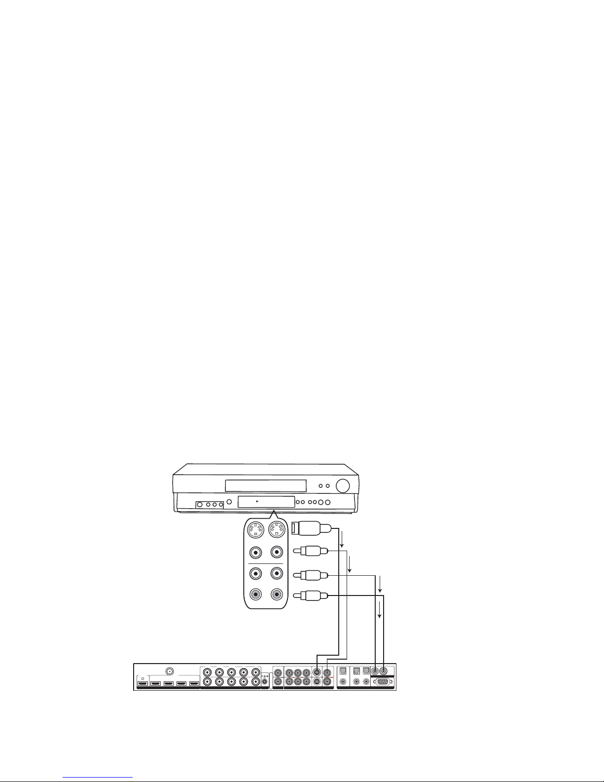
VCR/LD Player/DVR
NOTE: Some VCRs and LD players have S-Video outputs. These give an improved picture from these
sources. If your LD player or DVR has a digital audio output, ABT recommends you use that connection
11
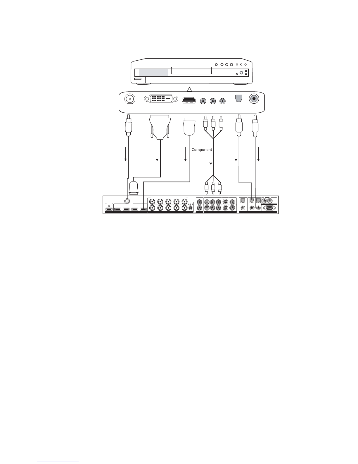
DVD Player/DVD Recorder
HD MI
1 2 3 4
INPUT
OUTPUT
1
324
SERIAL PORT
ANALOG AUDIO INPUT
Y (G) Pb (B) Pr (R) H V
Y (G) Pb (B) Pr (R)
1
212
121
2
CO MP ON E NT
L R
AN AL OG VI DE O
OUTPUT
I
I
N
P
U
T
O
U
T
P
U
T
DI GI TA L A UD IOS-VIDEO VI DEOSYNCPOWER
INPUT
DC In
P
U
T
S
DVI-D OUT (HDCP)
HDMI OUT
OPTICAL COAXIAL
HDMI
HDMI
SDI OUT
DVI-D
HDMI Optical
Audio
Coaxial
Audio
SDI
COMPONENT OUT
DVI-
HDMI
NOTE: If you have a display with an HDMI/DVI input, ABT recommends you use the DVI/HDMI output of
your DVD player with the player’s output resolution set to the lowest output resolution (preferably 480i.
With a component connection, set the player’s output to 480i, minimizing the amount of processing done
in the player.
12
 Loading...