


Rev. 0128/01
TRONIC
SERVICE MANUAL
SYSTEMS
1
CONTENTS
1.0) CALIBRATION AND TEST MENU
1.1) CALIBRATION MENU ACCESSING PROCEDURE
1.2) REFRIGERANT SCALE CALIBRATION
1.3) MAINTENANCE METER CALIBRATION (RESET)
1.4) COMPONENTS AND FUNCTIONS TEST MENU
1.5) OPERATION PARAMETERS SETTING MENU
1.6) TABLE OF COMPONENT CODES
2.0) LIST OF COMPONENTS VIEW
2.1) GENERAL OVERVIEW
2.2) CONTROL PANEL VIEW
2.3) REAR VIEW
2.4) REFRIGERANT CONTAINER SAFETY VALVES
2.5) FRONT PART, INSIDE VIEW
2.6) UPPER PART, INSIDE VIEW
2.7) POWER BOARD VIEW
2.8) LOGIC BOARD VIEW
2.9) FLOW DIAGRAM
2.10) ELECTRICAL DIAGRAM
2.11) TABLE OF CONNECTIONS
Rev. 0128/01
TRONIC
SERVICE MANUAL
SYSTEMS
2
1.0) CALIBRATION AND TEST MENU
1.1) CALIBRATION MENU ACCESSING PROCEDURE
WARNING: PERFORM THIS PROCEDURE ONLY AFTER HAVING READ THE
FOLLOWING INSTRUCTIONS CAREFULLY. IF NOT PERFORMED PROPERLY, THIS
PROCEDURE CAN CAUSE MALFUNCTIONING AND DAMAGE THE UNIT.
Supply power to the unit.
With the display showing the net weight available (Stand-by mode), proceed as descri be d
below:
Press the UP Key and keep it pressed.
Press the S Key and keep it pressed.
Release the UP Key.
Press the DOWN Key and keep it pressed.
Release the S Key.
Release the DOWN Key.
The display shows 0000.
Use the UP-DOWN keys to access the following menus:
0001 Refrigerant scale calibration.
0005 Maintenance meter calibration (reset).
0015 Components and fu nctions test menu.
0050 Printer enabling.
0567 Operation parameter setting menu.
Set the desired menu.
Use the S key to confirm.
See the chapters on the individual menus.

Rev. 0128/01
TRONIC
SERVICE MANUAL
SYSTEMS
3
1.2) REFRIGERANT SCALE CALIBR ATIO N
Required equipment:
1 Phillips screwdriver, PH 2.
1 Hexagonal spanner no.13.
1 Sample weight, 5 Kg.
2 Sample weights, 2 Kg.
1 Sample weight, 1 Kg.
Or, alternatively:
1 Sample weight, min. 10 Kg.
1 Known weight, 9 Kg.
After removing the front panel, remove the M8 screw that fastens the container (34) to the
scale plate (18). Remove the container (34).
Note: it is not necessary to disconnect the hoses from the internal container (34).
Set menu 0001 (see Chap.1.1), confirm with the S Key.
The display shows P- - - 0.
With the scale plate (18) completely empty, press the S Key.
The display shows P- - - F.
Position the 10-Kg sample weight (or weights) on the scale plate (18).
Confirm with the S Key.
The display shows the theoretical weight read by the scale.
Use the UP-DOWN Keys to set the sample weight value.
Confirm with the S Key.
Remove the 10-Kg sample weight.
The display shows P- - - t.
Position 9-Kg sample weight (or weights) on the scale plate (18).
Confirm with the S Key.
The display shows –End–.
Press the S Key to exit. The display shows the Stand-by mode.
End of procedure.

Rev. 0128/01
TRONIC
SERVICE MANUAL
SYSTEMS
4
1.3) MAINTENANCE METER CALIBRATIO N ( RE S ET)
Set menu 0005 (see Chap.1.1), confirm with the S Key.
The display shows cont.
Press the S Key.
The display shows the work time (maximum time of 3600).
Press the S Key and keep it pressed.
The display shows cont – rESEt alternately.
When the display shows 0000, release the S Key.
The display shows –End–.
Press the S Key to exit. The display shows the Stand-by mode.
End of procedure.

Rev. 0128/01
TRONIC
SERVICE MANUAL
SYSTEMS
5
1.4) COMPONENTS AND FUNCTIONS TEST MENU
This procedure can be used to check the operation of the unit’s component s.
Set menu 0015 (see Chap.1.1), confirm with the S Key.
The display shows tESt 1.
When the F Key is pressed repeatedly, the following tests can be selected sequentially:
Test 1 All display segments check.
Test 2 All leds check.
Test 4 Out C and keys check.
Test 5 Refrigerant scale net weight visualization.
Test 6 Pressure transducer visualization (mV).
Test 7 Not used
Test 8 Not used
Test 9 Printer test. (If installed)
–End– Exit.
Use the F Key to select the desired menu.
Confirm with the S Key.
Use the S Key to exit from the individual tests.
With the display showing –End–, press the S Key to exit. The display shows the Stand-by
mode.
End of procedure.
Rev. 0128/01
TRONIC
SERVICE MANUAL
SYSTEMS
6
1.5) OPERATION PARAMETER SETTING MENU
WARNING: PERFORM THIS PROCEDURE ONLY AFTER HAVING READ THE
FOLLOWING INSTRUCTIONS CAREFULLY. IF NOT PERFORMED PROPERLY, THIS
PROCEDURE CAN CAUSE MALFUNCTIONING AND DAMAGE THE UNIT.
Set menu 0567 (see chap. 1.1),confirm with the S Key.
Press the F key repeatedly to select the following operation parameters in sequence:
CODE
VALUE
P-t02
60
P-t03
180
P-t04
60
P-t05
45
P-t06
04
P-t07
05
P-t08
02
P-t09
60
P-t10
00
P-t11
09
P-t12
60
P-t13
05
P-t14
240
P-t15
05
P-udL
0.700
P-udH
1.400
P-ud1
0.120
P--Fd
1.000
rES
P--Lb
10.000
t--AL
3600
When the display shows u---F, the pressure transducer can be calibrated.
Disconnect the quick connectors from the high and low pressure hoses.
Open the LP-HP valves on the control panel to connect the pressure transducer to the
atmospheric pressure.
With the display showing u---F, confirm with the S key.
The display shows the theorical weight measured.
Digit the value 0.960. Confirm with the S key.
Rev. 0128/01
TRONIC
SERVICE MANUAL
SYSTEMS
7
The display shows the following parameters:
P---M
19.500
rES
P-CFd
00.700
-End-
OUT
Use the F key to select the desired parameter and confirm by pressing the S key.
Use the UP-DOWN keys to set the value shown in the table.
Confirm with the S key.
Select the parameter -End- and confirm with the S key to exit.
The display shows the net weight available (standby).
End of procedure.

Rev. 0128/01
TRONIC
SERVICE MANUAL
SYSTEMS
8
1.6) TABLE OF COMPONENT CODES
1
TRONIC 2K1 LOGIC BOARD
2
POWER CABLE
3
LP BALL VALVE
4
HP BALL VALVE
5
2200 mm BLUE CHARGING HOSE
6
2200 mm RED CHARGING HOSE
7
LP QUICK CONNECTOR
8
HP QUICK CONNECTOR
10
HP D80 GAUGE
11
LP D80 GAUGE
12
–1/10 bar PRESSURE SENSOR
13
DISTILLATOR
14
OIL SEPARATOR
15
DRYING FILTER
16
140 KPL COMPRESSOR
17
4,3 m3/h VACUUM PUMP
18
60 Kg LOAD CELL
20/21
OIL INJECTION/DRAIN CONTAI NER
22
EXPANSION VALVE
25
500mm STRAIGHT+STRAIGHT HOSE
26
500 mm 90°+STRAIGHT HOSE
27
FAN CONDENSER
28
HP PRESSURE SWITCH
29
PROTECTION WIRE
30
500 mm 90°+STRAIGHT HOSE
31
CHECK VALVE M/F
32
CHECK VALVE
33
11,8 bar UNCONDENSABLES DISCHARGE VAL VE
34
INTERNAL REFRIGERANT CONTAI NER
39
500 mm STRAIGHT+STRAIGHT HOSE
40
PRINTER SET (OPTIONAL)
41
PAPER WIND KEY (OPTIONAL)
42
KPL DOUBL E POLE SWITCH
43
UPPER PANEL
45
FRONT PANEL
46
A200 REAR WHEEL
47
ROTATING FRONT WHEEL WITH BRAKE
48
SIDE POCKET
49
IDENTITY LABEL
50
KPL MANIFOLD
53
15 bar SAFETY VALVE
60
6 OUT 2K1 POWER BOARD

Rev. 0128/01
TRONIC
SERVICE MANUAL
SYSTEMS
9
2.0) LIST OF COMPONENTS VIEW
2.1) GENERAL OVERVIEW (Picture. 1)
41
40 43
OPTIONAL
20
1
21
48
46
4
10
11
3
8
6
7
5
45
47

Rev. 0128/01
TRONIC
SERVICE MANUAL
SYSTEMS
10
2.2) CONTROL PANEL VIEW (Picture.2)
10
11
S LED S
DOWN
UP
LED G
LED T
LED W
LED P
LED C
LED D
LED B
LED A
LED F
F
3
4
Rev. 0128/01
TRONIC
SERVICE MANUAL
SYSTEMS
11
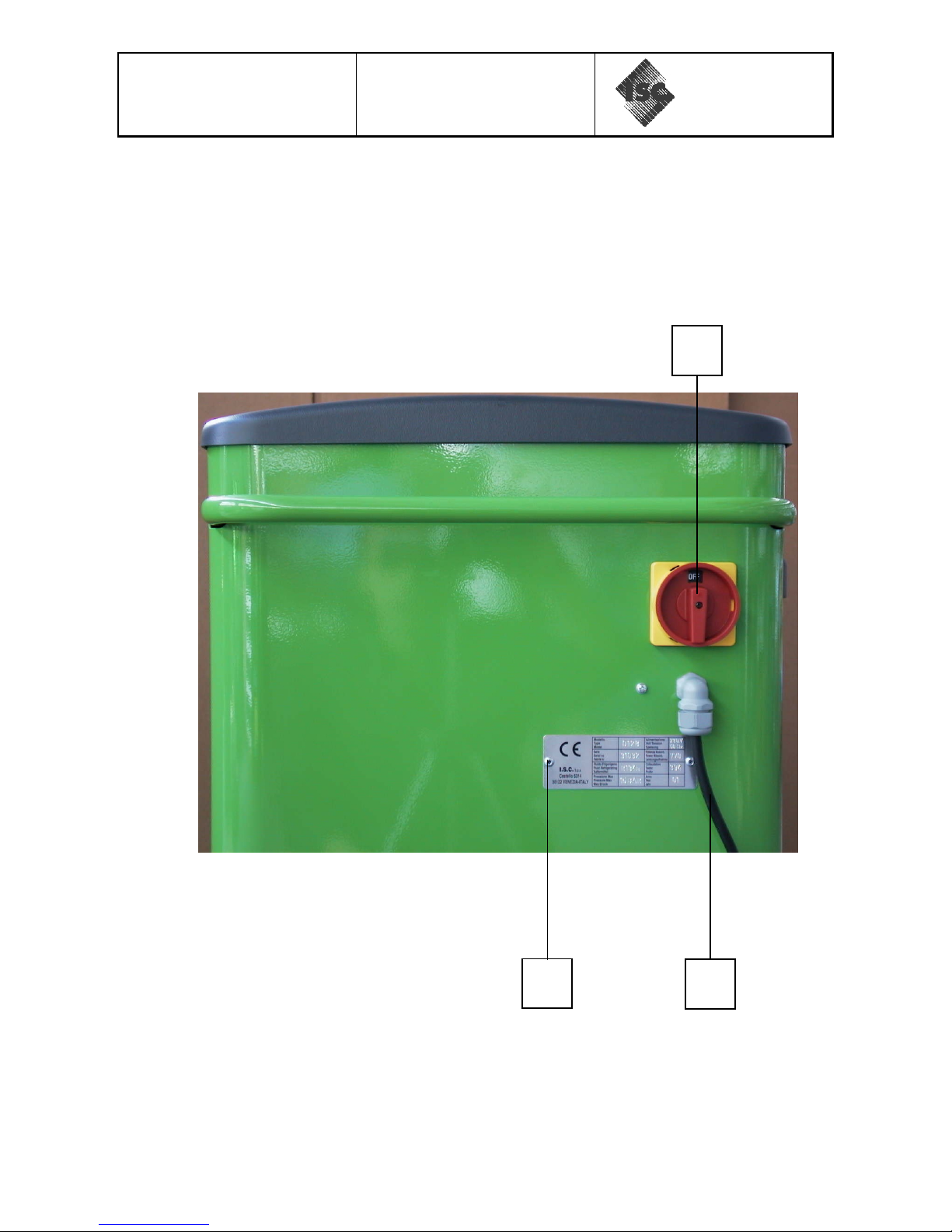
2.3) REAR VIEW (Picture. 3)
42
2
49

Rev. 0128/01
TRONIC
SERVICE MANUAL
SYSTEMS
12
2.4) REFRIGERANT CONTAINER SAFETY VALVES (Picture. 4)
31
53
33
34
25
39

Rev. 0128/01
TRONIC
SERVICE MANUAL
SYSTEMS
13
2.5) FRONT PART, INSIDE VIEW (Pictur e. 5 )
29
22
28
30
25
34
18
17
16
27
65
15
13/14
39

Rev. 0128/01
TRONIC
SERVICE MANUAL
SYSTEMS
14
2.6) UPPER PART, INSIDE VIEW (Pictur e.6 )
POS
NAME
DESCRIPTION
61A
OUT B
SOLENOID VALVE ø4.5 mm
61B
OUT B
SOLENOID VALVE ø4.5 mm
62A
OUT A
SOLENOID VALVE ø3mm
62B
OUT A
SOLENOID VALVE ø4.5 mm
63
OUT R
SOLENOID VALVE ø2.5 mm
64
OUT L
SOLENOID VALVE ø2.5 mm
60
CHECK VALVE
42
12
50
61A
61B
62B
62A
63
64

Rev. 0128/01
TRONIC
SERVICE MANUAL
SYSTEMS
15
2.7) POWER BOARD VIEW (Picture.7)
71
81
80
72
74
75
76
73
79
78
77
70
Rev. 0128/01
TRONIC
SERVICE MANUAL
SYSTEMS
16
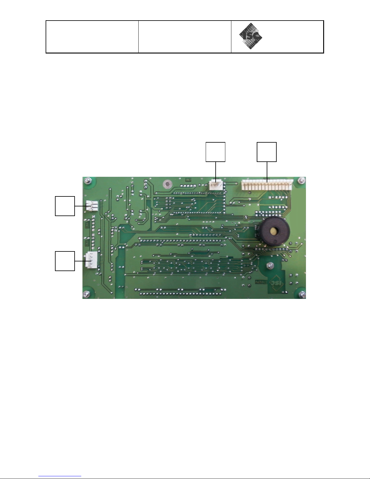
2.8) LOGIC BOARD VIEW (Picture.8)
82
83
85
84

Rev. 0128/01
TRONIC
SERVICE MANUAL
SYSTEMS
17
2.9) FLOW DIAGRAM

Rev. 0128/01
TRONIC
SERVICE MANUAL
SYSTEMS
18
2.10) ELECTRICAL DIAGRAM

Rev. 0128/01
TRONIC
SERVICE MANUAL
SYSTEMS
19
2.11) TABLE OF CONNECTIONS
PIC.
POS.
NAME
N°PIN
DESCRIPTION
DESTINATION
6
61
OUT B
-
VACUUM SV
-
6
62
OUT A
-
RECOVERY SV
-
6
63
OUT R
-
FILLING SV
-
6
64
OUT L
-
INJECT. SV OIL
-
6
65
OUT S
-
DRAIN OIL SV
-
6
12
PRESS.SENSOR.
-
PRESS.SENSOR.
-
6
42
SWITCH
-
SWITCH
-
7
70
PRINTER
2
POWER. PRINTER
PRINTER (40)
7
71
J2
10
DATA LINE
LOGIC BOARD (1)
7 72 PROTECT 2
PRESSURE
SWITCH INPUT
PRESSURE SWITCH
(28)
7 73 COMPRESS 3
POWER. COMP
(OUT C)
COMPRESSOR (16)
7 74 PUMP 3
POWER. PUMP
(OUT P)
VACUUM PUMP (17)
7 75 PUMP 3
POWER. VACUUM
SV (OUT B)
OUT B
7 76 OUT 1 3
POWER.
RECOVERY SV
(OUT A).
OUT A
7 77 OUT 3 3
POWER. INJECT.
OIL SV (OUT L)
OUT L
7 78 OUT 4 3
POWER. FILLING
SV (OUT R)
OUT R
7 79 OUT 6 3
POWER. OIL DRAIN
SV (OUT S)
OUT S
7
80
LINE OUT
3
220V 50 Hz LINE
NOT USED
7
81
LINE IN
3
POWER IN.
-
8
82
CN 8
15
DATA LINE
POWER BOARD (60)
8 83 CN 7 4
OUT. PRINTER
DATA
PRINTER (40)
8
84
CN 2
5
IN. REFRIG. CELL.
REFRIG. CELL. (18)
8 85 CN 5 3
IN. PRESSURE
SENSOR
PRESSURE SENSOR
(12)

Rev. 0128/01
TRONIC
SERVICE MANUAL
SYSTEMS
20
CONTROL PANEL
SFUP
DOWN
 Loading...