


PKS 1700 B2 (LB 6)
Sliding Mitre Saw
Artikel-Nr.: 4300684
Ident-Nr.: 01029
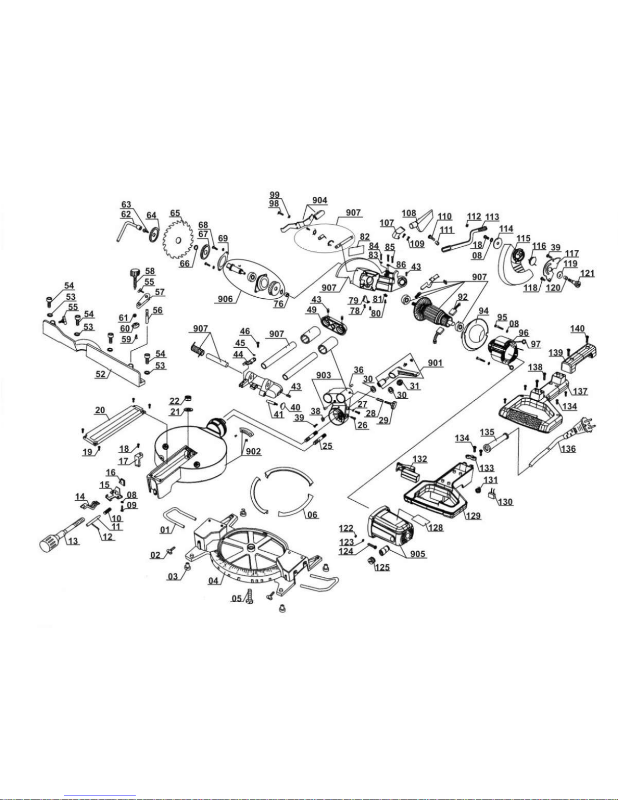
Komponenten / Ersatzteile
Position Artikel-Nr. Beschreibung
Position Artikel-Nr. Beschreibung
1 430072201004 Extension Bar
2 430072201005 Wing Handle für Werkstückauflage
3 430066102003 Base Pad
6 430066102006 Rotatory Steel Piece
8 430066102008 Pad
9 430066102009 Screw
10 430066102010 Small Spring
11 430066102011 Locking Bolt
12 430066102012 Locking Bolt
13 430072201007 Locking Handle
14 430066102014 Locking Release
15 430066102015 Steel Piece For Spring
16 430066102016 Holder For The Steel Piece
17 430066102017 Pointer
18 430066102018 Cross-tapping Screw
19 430066102019 Cross-tapping Screw

Komponenten / Ersatzteile
Position Artikel-Nr. Beschreibung
Position Artikel-Nr. Beschreibung
20 430066102020 Kerf Board
26 430066102026 Screw
29 430066102029 Locking Nut For Sliding Bar
30 430066102030 Nut
31 430066102031 Lid Of Bolt
39 430066102039 M6*8 Screw M6 x 8
40 430066102040 Locking Handle
44 430066102044 Depth Adjuster Piece
52 430072201008 stop bar
55 430066102055 Wing-Shape Handle
56 430066102056 Position Bar
57 430066102057 Locking Bar
58 430066102058 Position Handle
59 430066102059 Screw
60 430066102060 Plate
61 430066102061 Washer
62 430072201012 Wrench
63 430066102063 Bolt
66 430066102066 Position Ring
67 430066102067 Inner Flange
92 430066102092 Carbon Brush (pair)
92 430072201013 carbon brush (pair)
96 430066102096 Field
107 430066102107 Dust Outlet
108 430072201009 dust bag
109 430066102109 Screw
110 430066102110 Screw1
111 430066102111 Ring
112 430066102112 nut M5
113 430066102113 Contact Bar
114 430066102114 Pad For Movable Guard
115 430072201003 Movable Guard
116 430066102116 Spring
117 430066102117 Spring Pad
118 430066102118 Screw
119 430066102119 Position Pad For Movable Guard
120 430066102120 Ring2
121 430066102121 Screw
123 430066102123 Washer 6mm
129 430066102129 Handle
132 430072201001 on/off switch
133 430066102133 Pad For Cable
134 430066102134 Screw
135 430066102135 Cable Holder
137 430066102137 Lid For Handle
139 430066102139 Holder
901 430072201010 locking handle comp.
903 430066102903 Supporter comp.
904 430072201002 Self-Release comp.
906 430066102906 gear compl.
908 430072201006 table insert inkl. Befestigungsschrauben
SLIDING CROSS CUT MITRE SAW
Operation and Safety Notes
6
SLIDING CROSS CUT
MITRE SAW
ZKGS 2100
Anleitung_4300684:_ 24.11.2009 16:25 Uhr Seite 1
Before reading, unfold the page containing the illustrations and familiarise yourself with all functions of the
device.
GB/IE/CY Operation and Safety Notes Page 8
Anleitung_4300684:_ 24.11.2009 16:25 Uhr Seite 2
3
1
2 3
2
3
5
4
6
7
8
9
10
12
11
18
17
12
22
26
25
24
23
18
27
33
1
19
22
8
20
21
10
9
13 17
15
16 14
13
28
18
c
Anleitung_4300684:_ 24.11.2009 16:25 Uhr Seite 3
4
8
5
76
9
17
29
d
21
7
z
10
4
13
18
9
16
20
30
23
29
d
Anleitung_4300684:_ 24.11.2009 16:25 Uhr Seite 4

5
11
12
10
y
17
1
8
30
13
14
7
15
2
3
5
19
16
17
8
5
16
8
5
16
5
8
16
15
13
Anleitung_4300684:_ 24.11.2009 16:25 Uhr Seite 5
6
17
18
c
19
20
6
4
31
32
7
21
35
38
34
16
27
28
Anleitung_4300684:_ 24.11.2009 16:25 Uhr Seite 6

7
23
37
22
36
33
Anleitung_4300684:_ 24.11.2009 16:25 Uhr Seite 7

GB/IE/
CY
8
Table of contents Page
1. Introduction .............................................................................9
2. Safety information ..................................................................9-13
3. Layout .....................................................................................13
4. Items supplied.........................................................................14
5. Intended use ..........................................................................14
6. Technical data.........................................................................15
7. Before starting the equipment .................................................15-16
8. Operation ................................................................................16-18
9. Replacing the power cable......................................................18
10. Cleaning, maintenance and ordering of spare parts................18
11. Disposal and recycling............................................................19
12. Declaration of conformity ........................................................20
13. Guarantee certificate...............................................................21
The reprinting or reproduction by any other
means, in whole or in part, of documentation
and papers accompanying products is
permitted only with the express consent of ISC
GmbH.
Subject to technical changes
Anleitung_4300684:_ 24.11.2009 16:25 Uhr Seite 8

9
GB/IE/
CY
1. Introduction
Important.
When using the equipment, a few safety
precautions must be observed to avoid injuries
and damage. Please read the complete
operating instructions and safety information
with due care. Keep this manual in a safe place
so that the information is available at all times. If
you give the equipment to any other person,
hand over these operating instructions and the
safety information as well. We cannot accept
any liability for damage or accidents which arise
due to a failure to follow these instructions and
the safety information.
2. Safety information
CAUTION
Read all the safety information and
instructions. Any errors made in following the
safety information and instructions set out
below may result in an electric shock, fire
and/or serious injury.
Keep all the safety information and
instructions in a safe place for future use.
Explanation of the symbols on the
equipment
Note the instructions for use!
Important. Risk of injury. Never reach
into the running saw blade!
Wear a breathing mask if dust is
generated!
Wear ear-muffs!
Wear safety goggles!
Wear safety gloves!
2.2 General safety information on electric
power tools
Important. The following safety precautions
must be taken when using electric power
tools in order to protect the user from
electric shocks and the risk of injury and
fire. Read and follow these instructions
before using the equipment.
Keep your work area tidy
- Untidy work areas can result in accidents.
Make allowance for ambient conditions
- Do not expose electric power tools to rain.
Never use electric power tools in damp or
wet locations. Provide good lighting. Do not
use electric power tools near flammable
liquids or gases.
Guard against electric shock
- Avoid bodily contact with earthed parts
(e.g. pipes, radiators, cookers and
refrigerators).
Keep children away
- Do not allow other persons to touch the
equipment or cable, keep them away from
your work area.
Keep your electric power tools in a safe
place.
- Unused tools must be stored in a dry,
locked room out of children’s reach.
Do not overload your tools
- It will work better and safer when used
within its quoted capacity range.
Use the right tool
- Do not use tools or attachments too weak
for heavy duty work. Never use tools on
jobs for which they are not intended; for
example, do not use a hand-held circular
saw to fell trees or lop off branches.
Wear suitable work clothes
- Never wear loose fitting clothes or jewelry.
They may get caught in moving parts.
Rubber gloves and non-slip shoes are
recommended when working outdoors.
Wear a hair net if you have long hair.
Wear safety goggles.
- Use a dust mask when working on dusty
jobs.
Do not use the cable for purposes other
than that for which it is designed.
- Do not carry the equipment by its cable
Anleitung_4300684:_ 24.11.2009 16:25 Uhr Seite 9

10
GB/IE/
CY
and do not use the cable to pull the plug out
of the socket. Protect the cable from heat,
oil and sharp edges.
Secure your workpiece
- Use clamps or a vise to hold the workpiece
securely. This is safer than using your hand
and also enables you to operate the
machine with both hands.
Do not overstretch.
- Avoid abnormal working postures. Make
sure you stand squarely and keep your
balance at all times.
Take care of your tools
- Keep your tools sharp and clean in order
to work well and safely. Follow the
maintenance information and the
instructions for changing tools. Check the
power plug and cable on a regular basis
and have them replaced by an authorized
specialist if they are damaged. Check the
extension cable regularly and replace it if
damaged. Keep handles dry and free from
oil and grease.
Pull the power plug
- When tools are not in use, before starting
any maintenance work or when changing
attachments such as saw blades, drill bits
and all kinds of mounted tools.
Always remove keys and wrenches after
use
- Before switching on, make sure that all
keys and wrenches have been removed
from the tool.
Avoid unintentional starting
- Never carry a tool with your finger on the
switch button while the tool is connected to
the power supply. Make sure that the switch
is turned off when connecting the tool to the
power supply.
When using an extension cable
outdoors
- Check that it is approved for outdoor duty
and is marked accordingly.
Be alert at all times
- Keep an eye on your work. Use common
sense when working. Never use the tool
when you are distracted.
Check the equipment for damage
- Before using the tool again, check the
safety devices or any slightly damaged
parts to ensure that they are in good
working order. Check that the moving parts
are working correctly, that they do not jam,
and that no parts are damaged. Make sure
that all parts are fitted correctly to ensure
that the equipment remains safe to use.
Unless otherwise stated in the operating
instructions, damaged guards and parts
have to be repaired or replaced by a
customer service workshop. Damaged
switches have to be replaced by a customer
service workshop. Never use an electric
power tool with a switch that cannot be
turned on and off.
Important!
- For your own safety you must only use the
accessories and additional units listed in the
operating instructions or recommended or
specified by the manufacturer. The use of
mounted tools or accessories other than
those recommended in the operating
instructions or catalog may place your
personal safety at risk.
Repairs may only be carried out by a
qualified electrician
- This electric power tool complies with the
pertinent safety information. Repair work
must only be carried out by a trained
electrician, otherwise the equipment may
cause accidents.
Connect up a vacuum extraction system
- If there are provisions for connecting up a
vacuum extraction system, make sure that
such a system is fitted and in use.
2.3 Special safety information on the
equipment
1. Safety precautions
Change a worn out table insert.
Use only blades which are recommended
by the manufacturer and comply with EN
847-1.
If necessary, wear suitable personal
protection equipment. This could consist of:
- Ear plugs to prevent the risk of damaging
your hearing
- A breathing mask to avoid the risk of
inhaling hazardous dust
- Always wear gloves when handling saw
Anleitung_4300684:_ 24.11.2009 16:25 Uhr Seite 10

GB/IE/
CY
11
blades and rough materials. Whenever
practicable, saw blades must be carried in a
container.
The following can have an influence on dust
development:
- Worn, damaged or cracked saw blades
- Recommended capacity of the vacuum
extraction system: 20 m/s
- Proper guidance of the workpiece
Blades made of high-alloy high-speed steel
(HSS) must not be used.
2. Safety information on the laser
Important:
Laser radiation
Do not look into the beam
Laser class 2
Protect yourself and your environment from
accidents by taking the appropriate
precautionary measures.
Do not look directly into the laser beam with
the naked eye.
Never look directly into the laser path.
Never direct the laser beam at reflecting
surfaces, persons or animals. Even a low
output laser beam can inflict injury on the
eye.
Caution: It is vital to follow the work
procedures described in these instructions.
Using the equipment in any other way may
result in hazardous exposure to laser
radiation.
Never open laser module.
When the laser is not going to be used for
an extended period of time, the batteries
should be removed.
Never use an optical instrument (for
example magnifying glass) to view the laser
beam.
Check the laser for damage on a regular
basis and always before use. To protect
yourself against injury, never use the
equipment if it is damaged.
Defective lasers have to be repaired by a
customer service workshop.
3. Safety information on the batteries
Never recharge the batteries. Danger of
explosion.
Keep batteries out of the reach of children.
Do not throw batteries into the fire, shortcircuit or take them apart.
If necessary clean the contacts on the
batteries and equipment before inserting the
batteries.
Remove flat batteries immediately from the
equipment. Risk of leakage!
Always replace all batteries in one go. Only
use new batteries of the same make.
Avoid contact with skin, eyes and mucous
membranes. If you come into contact with
battery acid, rinse the affected pars at once
with plenty of clear water and seek
immediate medical assistance.
Do not expose batteries to extreme
conditions, e.g. do not place on heaters or
in direct sunshine. Increased risk of
leakage.
4. Maintenance and service
The following conditions can have an
influence on noise impact on the operator:
- Type of saw blade (e.g. saw blades
designed to reduce noise development)
- Material of the workpiece
- The force with which the workpiece is
pushed against the saw blade
Faults on the machine or its guards, safety
devices and blade must be reported to the
person in charge as soon as they are
discovered.
5. Safe operation
Use a suitable blade for the material you
wish to saw.
Never use the drag, crosscut and miter saw
to cut any materials other than those
specified by the manufacturer.
Use only the transport devices to move the
equipment. Never use the guards for
handling or moving the equipment.
Anleitung_4300684:_ 24.11.2009 16:25 Uhr Seite 11

GB/IE/
CY
12
Use the saw only if it is in perfect condition
and properly maintained.
When cutting miters, make sure that the
device for swiveling the arm is fastened
securely.
The floor around the machine must be level,
clean and free of loose particles, such as
chips and cutting residues.
The operator must receive proper training in
the use, adjustment and operation of the
machine.
Only use properly sharpened saw blades.
Do not exceed the maximum speed
specified on the blade.
Be sure to only use spacers and spindle
rings specified by the manufacturer as
suitable for the intended purpose.
If the machine is equipped with a laser, this
laser may not be replaced by a different
type of laser. Repairs may only be carried
out by the manufacturer of the laser or one
of his authorized agents.
Do not remove any cutting residues or other
parts of workpieces from the cutting zone
while the machine is running and the saw
unit is not at rest.
Make sure that the machine is always
secured on a workbench or a table if at all
possible.
Support long workpieces (e.g. with a roller
table) to prevent them sagging at the end of
a cut.
6. Additional safety information on
crosscut saws
Give these safety instructions to all persons
who work on the machine.
Do not use this saw to cut fire wood.
Caution! Hands and fingers may be injured
on the rotating saw blade.
Before you use the machine for the first
time, check that the voltage marked on the
rating plate is the same as your mains
voltage.
If you need to use an extension cable, make
sure its conductor cross-section is big
enough for the saw’s power consumption.
Minimum cross-section: 1.5 mm
2
.
If you use a cable reel, the complete cable
must be pulled off the reel.
Operators have to be at least 18 years of
age. Trainees of at least 16 years of age are
allowed to use the machine under
supervision.
Persons working on the machine should not
be distracted.
Note the direction of rotation of the motor
and saw blade.
After you have switched off the motor, never
slow down the saw blade by applying
pressure to its side.
Only fit blades which are well sharpened
and have no cracks or deformations.
Faulty saw blades must be replaced
immediately.
Never use saw blades which do not comply
with the data specified in this manual.
It is imperative to make sure that the arrow
on the saw blade conforms with the arrow
on the machine.
Pull out the power plug and twist the blade
with your hand into the 45° and 90°
positions in order to make sure that the
blade does not touch the turntable in any
position. If necessary, readjust the saw
head.
It is imperative to make sure that all devices
which cover the saw blade are in good
working order.
Never wedge the hinged saw blade guard in
open position.
Never dismantle the machine’s safety
devices or render them inoperative.
Damaged or faulty safety devices have to
be replaced immediately.
Never cut workpieces which are too small to
hold securely in your hand.
Avoid placing your hands in hazardous
positions in which, one or both hands could
touch the saw blade if they slip suddenly.
Round workpieces such as plug rods, etc.
must always be clamped using a suitable
device.
There must be no nails or other foreign
bodies in the part of the workpiece that you
wish to saw.
Always stand to the side of the saw blade
when working with the saw.
Never load the machine so much that it cuts
out.
Anleitung_4300684:_ 24.11.2009 16:25 Uhr Seite 12

GB/IE/
CY
13
Always press the workpiece firmly against
the workbench and the stop rail to prevent
the workpiece wobbling or twisting.
Ensure that the off-cuts can be removed to
the side of the saw blade. Otherwise it is
possible that they will be caught by the saw
blade and catapulted out of the machine.
Never saw more than one workpiece at any
one time.
Never remove loose splinters, chips or
jammed pieces of wood when the saw
blade is running.
To rectify faults or remove jammed pieces
of wood, always switch off the machine first.
- Pull out the power plug-
Refit all guards and safety devices
immediately after you have completed any
repairs or maintenance work.
Be sure to observe the safety information
and operating and maintenance instructions
issued by the manufacturer, as well as the
dimensions listed in the Technical Data.
It is imperative to observe the accident
prevention regulations in force in your area
as well as all other generally recognized
rules of safety.
Note the information published by your
professional associations.
Operation in enclosed areas is permitted
only with a suitable vacuum extraction
system.
The crosscut saw has to be connected to a
230 V socket-outlet (shock-proof socket)
with earthing contact and minimum fusing of
10 A.
Do not use any low-powered machines for
heavy duty work.
Be careful when working in vertical mode.
Caution: Take extra care when making
double miter cuts!
Please keep these safety instructions in a
safe place
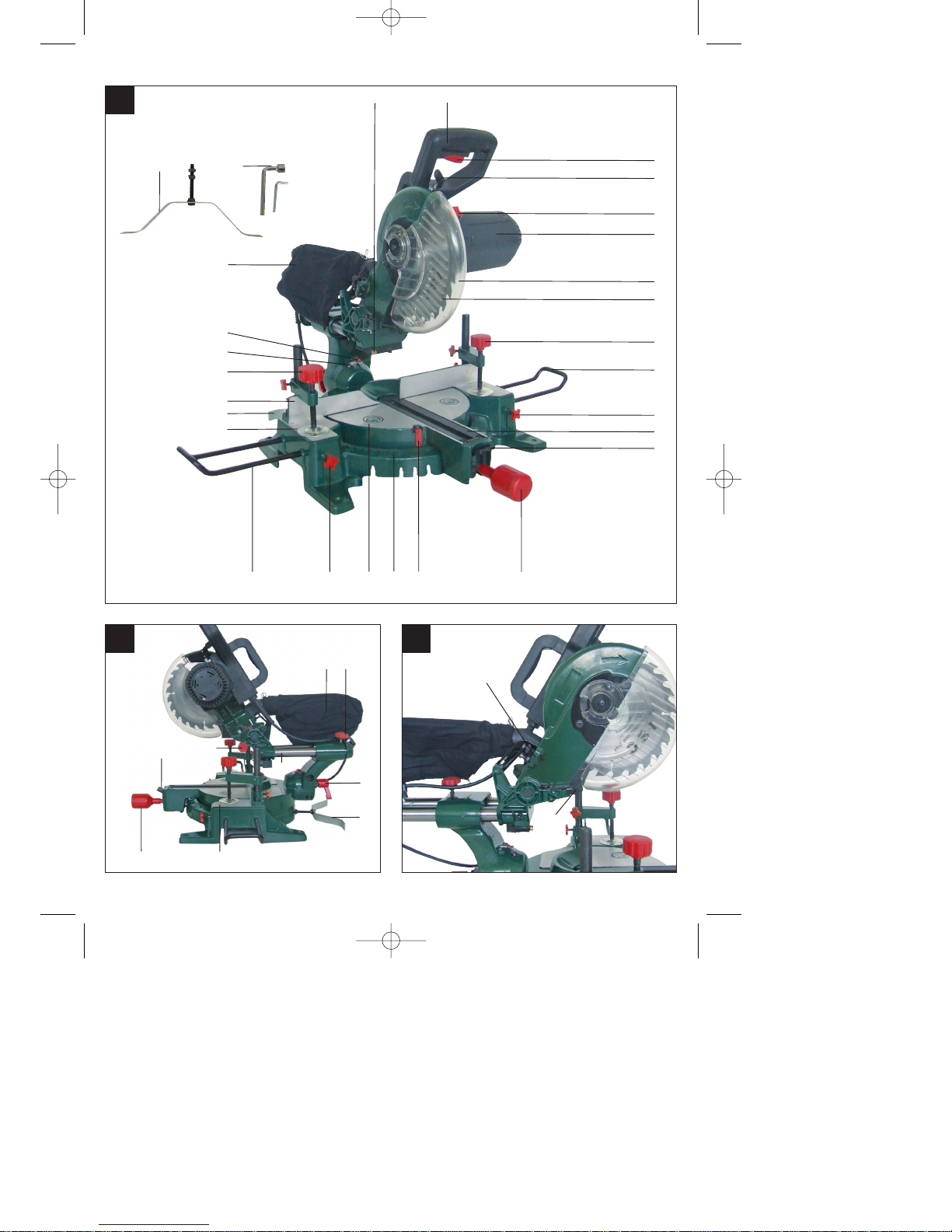
3. Layout
1. Handle
2. ON/OFF switch
3. Release lever
4. Saw shaft lock
5. Machine head
6. Movable blade guard
7. Saw blade
8. Clamping device
9. Workpiece support
10. Locking screw for workpiece support
11. Table insert
12. Latched position lever
13. Locking grip
14. Pointer
15. Scale
16. Turntable
17. Fixed saw table
18. Additional stability bar
19. Stop rail
20. Scale
21. Pointer
22. Sawdust bag
23. Locking screw
24. Locking screw for drag guide
25. Fastening bolt
26. Drag guide
27. Knurled screw for cutting depth limiter
28. Stop for cutting depth limiter
29. Adjustment screw (90°)
30. Adjustment screw (45°)
31. Flange bolt
32. Outer flange
33. Laser
34. ON/OFF switch for laser
35. Battery compartment
36. Battery compartment cover
37. Screw for adjusting the laser
38. Inner flange
c) Wrench
d) Counternut
y) 45° stop angle (not supplied)
y) 90° stop angle (not supplied)
Anleitung_4300684:_ 24.11.2009 16:25 Uhr Seite 13

4. Items supplied
Drag, crosscut and miter Saw
2 x Clamping device (8)
2 x Workpiece support (9)
Sawdust bag (22)
Allen key
Wrench (c)
Additional stability bar (18)
2 x Battery (1.5 V LR6)
5. Intended use
The drag, crosscut and miter saw is designed
to crosscut wood and plastic respective of the
machine’s size. The saw is not designed for
cutting firewood.
The equipment is to be used only for its
prescribed purpose. Any other use is deemed
to be a case of misuse. The user / operator and
not the manufacturer will be liable for any
damage or injuries of any kind caused as a
result of this.
Please note that our equipment has not been
designed for use in commercial, trade or
industrial applications. Our warranty will be
voided if the equipment is used in commercial,
trade or industrial businesses or for equivalent
purposes.
The equipment is to be operated only with
suitable saw blades. It is prohibited to use any
type of cutting-off wheel.
To use the equipment properly you must also
observe the safety information, the assembly
instructions and the operating instructions to be
found in this manual.
All persons who use and service the equipment
have to be acquainted with this manual and
must be informed about the equipment’s
potential hazards. It is also imperative to
observe the accident prevention regulations in
force in your area. The same applies for the
general rules of health and safety at work.
The manufacturer will not be liable for any
changes made to the equipment nor for any
damage resulting from such changes. Even
when the equipment is used as prescribed it is
still impossible to eliminate certain residual risk
factors. The following hazards may arise in
connection with the machine’s construction and
design:
Contact with the saw blade in the
uncovered saw zone.
Reaching into the running saw blade (cut
injuries).
Kick-back of workpieces and parts of
workpieces.
Saw blade fracturing.
Catapulting of faulty carbide tips from the
saw blade.
Damage to hearing if ear-muffs are not used
as necessary.
Harmful emissions of wood dust when used
in closed rooms.
The product meets the requirements of EN
61000-3-11 and is subject to special
connection conditions. This means that use
of the product at any freely selectable
connection point is not allowed.
Given unfavorable conditions in the power
supply the product can cause the voltage to
fluctuate temporarily.
The product is exclusively intended for use
at connection points that have a continuous
current-carrying capacity of at least 100 A
per phase.
As the user, you are required to ensure, in
consultation with your electric power
company if necessary, that the connection
point at which you wish to operate the
product meets the specified requirements.
GB/IE/
CY
14
Anleitung_4300684:_ 24.11.2009 16:25 Uhr Seite 14

GB/IE/
CY
15
6. Technical data
AC motor: 230V ~ 50Hz
Power: 1700 W
Operating mode: S1
Idle speed n0: 4,800 min
-1
Carbide saw blade: ø 210 x ø 30 x 2.8 mm
Number of teeth: 24
Swiveling range: -45° / 0°/ +45°
Miter cut: 0° to 45° to the left
Saw width at 90°: 205 x 65 mm
Saw width at 45°: 140 x 65 mm
Saw width at 2 x 45°
(double miter cut): 140 x 40 mm
Weight: approx. 15 kg
Laser class: 2
Wavelength of laser: 650 nm
Laser output: ≤ 1mW
Laser module power supply:
2 x 1.5 V Micro (AAA)
Noise emission values
The saw’s noise is measured in accordance
with EN 61029.
Idle speed
LpAsound pressure level 86 dB
KpAuncertainty 3 dB
LWAsound power level 99 dB
KWAuncertainty 3 dB
Vibration emission value a
h
< 2,5 m/s
2
Reduce noise generation and vibration to a
minimum!
Use only equipment that is in perfect
condition.
Maintain and clean the equipment regularly.
Adopt your way of working to the
equipment.
Do not overload the equipment.
Have the equipment checked if necessary.
Switch off the equipment when not in use.
Wear gloves.
7. Before starting the equipment
7.1 General information
The equipment must be set up where it can
stand securely, i.e. it should be bolted to a
workbench, a universal base frame or
similar.
All covers and safety devices have to be
properly fitted before the equipment is
switched on.
It must be possible for the blade to run
freely.
When working with wood that has been
processed before, watch out for foreign
bodies such as nails or screws, etc.
Before you press the ON/OFF switch check
that the saw blade is fitted correctly. Moving
parts must run smoothly.
Before you connect the equipment to the
power supply make sure the data on the
rating plate are identical to the mains data.
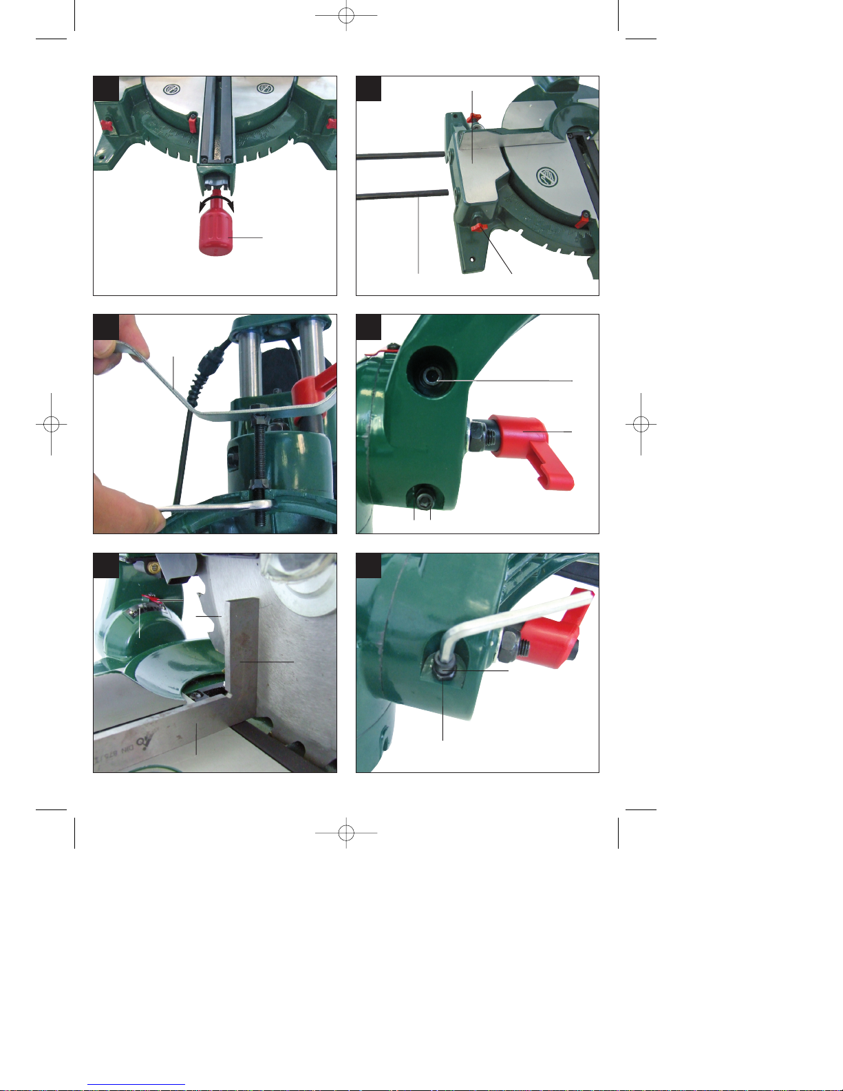
7.2 Assembling the saw (Fig. 1-2, 4-6)
To adjust the turntable (16), loosen the
locking grip (13) by approx. 2 turns, which
frees the turntable (16) (Fig. 4).
To release the saw from its bottom position,
apply light downward pressure to the
machine head (5). At the same time pull the
safety pin (25) out of the motor mount. Turn
the safety pin (25) through 90° so that the
saw remains unlocked (Fig. 1-2).
Swing the machine head (5) up until the
release lever (3) latches into place (Fig. 1).
Fit the clamping devices (8) on the left
and/or right side of the fixed saw table (17)
(Fig. 1).
Undo the locking screws for the workpiece
support (10) (Fig. 5).
Mount the workpiece support (9) on the
fixed saw table (17) and tighten the
appropriate locking screw (10) (Fig. 5).
Mount the second workpiece support (9) on
the opposite side of the saw and secure
with the appropriate locking screw (10).
When the locking screw (23) is loosened,
Anleitung_4300684:_ 24.11.2009 16:25 Uhr Seite 15

you can tilt the machine head (5) to the left
by up to 45° (Fig. 1-2).
Screw the additional stability bar (18) to the
back of the equipment (Fig. 6).
7.3 Precision adjustment of the stop for
crosscut 90° (Fig. 7-8)
No stop angle included.
Fasten the turntable (16) in 0° position.
Undo the locking screw (23) and move the
machine head (5) all the way to the right
using the handle (1).
Place the 90° angular stop (z) between the
blade (7) and the turntable (16).
Slacken the counternut (d). Adjust the
adjustment screw (90°) (29) until the angle
between the blade (7) and the turntable (16)
equals 90°.
Retighten the counternut (d) to secure this
setting.
Check the position of the pointer (21) on the
scale (20). If necessary, release the pointer
(21) with a crosstip screwdriver, move to the
0° position of the scale (20) and retighten.
7.4 Precision adjustment of the stop for
miter cut 45° (Fig. 1, 7, 10-11)
No stop angle included.
Fasten the turntable (16) in 0° position.
Undo the locking screw (23) and move the
machine head (5) all the way to the left
using the handle, until it coincides at 45°.
Place the 45° stop angle (y) between the
blade (7) and the turntable (16).
Adjust the adjustment screw (30) so that the
angle between the blade (7) and the
turntable (16) equals exactly 45°.
8. Operation
8.1 Cross cut 90° and turntable 0°
(Fig. 1-3, 12)
Important! The integral resetting springs will
automatically lift the machine head. Do not
simply let go of the handle (1) after cutting, but
allow the machine head (5) to rise slowly,
applying slight counter pressure as it does so.
For cutting widths up to approx. 100 mm it is
possible to fix the saw’s drag function with the
locking screw for drag guide (24) in rear
position. If the cutting width exceeds 100 mm
you must ensure that the locking screw for drag
guide (24) is slackened and that the machine
head (5) can be moved.
Move the machine head (5) to its upper
position.
Use the handle (1) to push back the
machine head (5) and fix it in this position if
required (dependent on the cutting width).
Place the piece of wood to be cut at the stop
rail (19) and on the turntable (16).
Lock the material with the clamping device
(8) on the fixed saw table (17) to prevent the
material from moving during the cutting
operation.
Push down the release lever (3) to release
the machine head (5).
Press the ON/OFF switch (2) to start the
motor.
With the drag guide (26) fixed in place: use
the handle (1) to move the machine head
(5) steadily and with light pressure
downwards until the saw blade (7) has
completely cut through the workpiece.
With the drag guide (26) not fixed in place:
pull the machine head (5) all the way to the
front. Lower the handle (1) to the very
bottom by applying steady and light
downward pressure. Now push the machine
head (5) slowly and steadily to the very
back until the saw blade (7) has completely
cut through the workpiece.
When the cutting operation is completed,
move the machine head (5) back to its
upper (home) position and release the
ON/OFF button (2).
8.2 Cross cut 90° and turntable 0° - 45°
(Fig. 1-3, 13)
The crosscut saw can be used to make
crosscuts of 0° -45° to the left and 0° -45° to the
right in relation to the stop rail.
Release the turntable (16) by slackening the
locking grip (13).
Press the latched position lever (12). Turn
the turntable (16) and scale pointer (14) to
the desired angular setting on the scales
GB/IE/
CY
16
Anleitung_4300684:_ 24.11.2009 16:25 Uhr Seite 16

(15) and lock into place with the locking grip
(13). The saw has locking positions at
angles of - 45°, -30°, -22.5°, -15°, 0°, 15°,
22.5°, 30° and 45°, at which you can
engage latched position lever (12).
Cut as described under section 8.1.
8.3 Miter cut 0°- 45° and turntable 0°
(Fig. 1-3, 14)
The crosscut saw can be used to make miter
cuts of 0° - 45° in relation to the work face.
If required, dismantle the clamping device
(8) or mount on the opposite side of the
fixed saw table (17).
Move the machine head (5) to its upper
position.
Fasten the turntable (16) in 0° position.
Undo the locking screw (23). Use the
handle (1) to tilt the machine head (5) to the
left until the pointer (21) points to the
required angle on the scale (20).
Re-tighten the fixing screw (23).
Cut as described in section 8.1.
8.4 Miter cut 0°- 45° and turntable 0°- 45°
(Fig. 1-3, 15)
The crosscut saw can be used to make miter
cuts to the left of 0°- 45° in relation to the work
face and, at the same time, 0° - 45° to the left or
0° - 45° to the right in relation to the stop rail
(double miter cut).
If required, dismantle the clamping device
(8) or mount on the opposite side of the
fixed saw table (17).
Move the machine head (5) to its upper
position.
Release the turntable (16) by slackening the
locking grip (13).
Press the latched position lever (12). Turn
the turntable (16) and scale pointer (14) to
the desired angular setting on the scales
(15) and lock into place with the locking grip
(13).
Undo the locking screw (23) and use the
handle (1) to tilt the machine head (5) to the
left until it coincides with the required angle
value (in this connection see also section
8.3).
Re-tighten the fixing screw (23).
Cut as described under section 8.1.
8.5 Limiting the cutting depth (Fig. 16)
The cutting depth can be infinitely adjusted
using the screw (27). To do this loosen the
knurled nut on the screw (27). Move the
stop for the cutting depth limiter (28) to the
outside. Turn the screw (27) in or out to set
the required cutting depth. Then re-tighten
the knurled nut on the screw (27).
Check the setting by completing a test cut.
8.6 Sawdust bag (Fig. 2)
The saw is equipped with a debris bag (22) for
sawdust and chips.
The debris bag (22) can be emptied by means
of a zipper at the bottom.
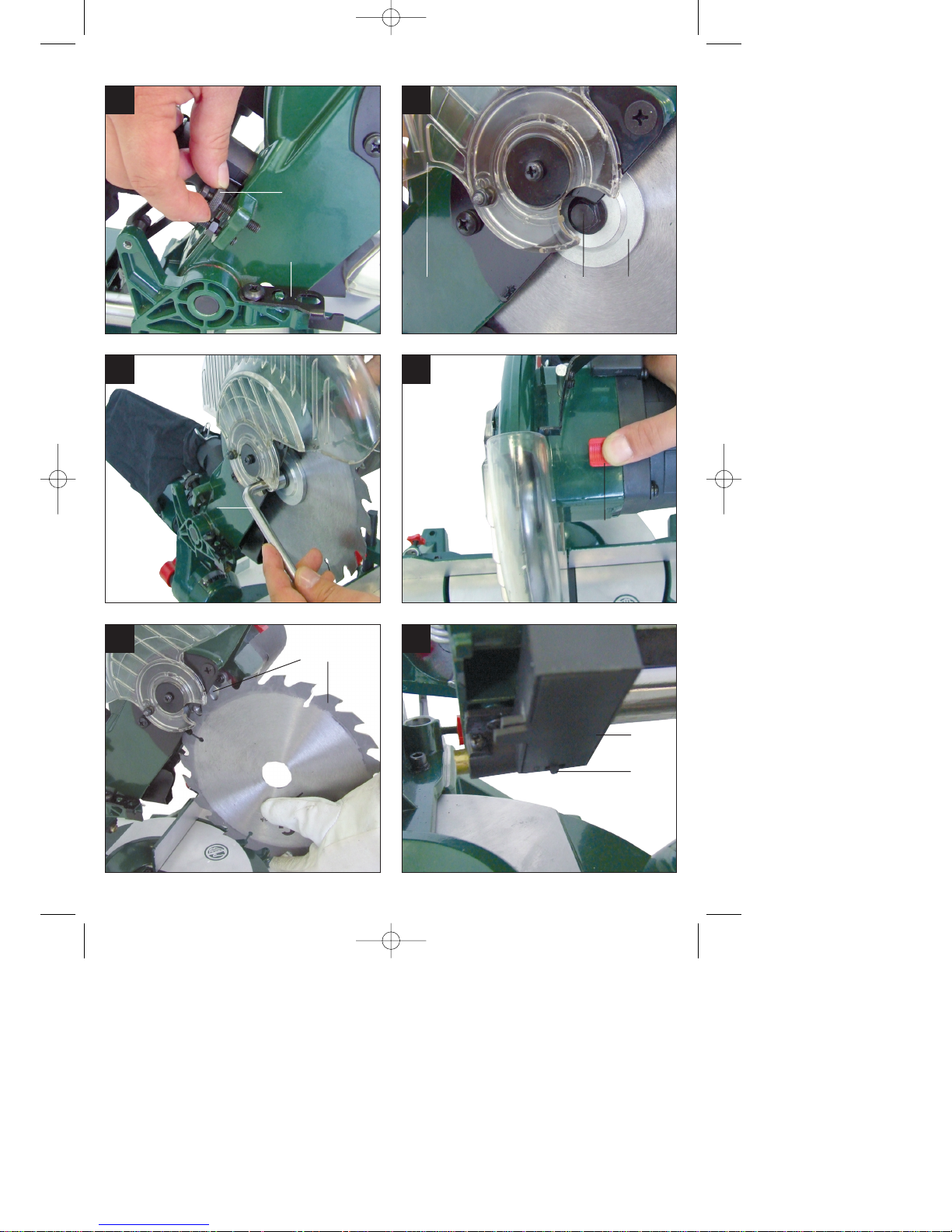
8.7 Changing the saw blade (Fig. 1, 17-20)
Remove the power plug!
Swing up the machine head (5). Use the
safety pin (25) to lock the machine head in
this position.
Press the release lever (3). Swing up the
saw blade guard (6) to the point where the
recess in the saw blade guard (6) is above
the flange bolt (31).
Press the saw shaft lock (4) with one hand.
With the other hand position the wrench (c)
over the flange bolt (31).
Firmly press the saw shaft lock (4) and
slowly rotate the flange bolt (31) in
clockwise direction. The saw shaft lock (4)
engages after no more than one rotation.
Now, using a little more force, slacken the
flange bolt (31) in the clockwise direction.
Turn the flange screw (31) right out and
remove the external flange (32).
Take the blade (7) off the inner flange (38)
and pull out downwards.
Carefully clean the flange screw (31), outer
flange (32) and inner flange (38).
Fit and fasten the new saw blade (7) in
reverse order.
Important! The cutting angle of the teeth, in
other words the direction of rotation of the
saw blade (7) must coincide with the
direction of the arrow on the housing.
Before continuing your work make sure that
all safety devices are in good working
condition.
Important! Every time that you change the
GB/IE/
CY
17
Anleitung_4300684:_ 24.11.2009 16:25 Uhr Seite 17

saw blade (7), check to see that it spins
freely in the table insert (11) in both
perpendicular and 45° angle settings.
Important! The work to change and align
the saw blade (7) must be carried out
correctly.
8.8 Transport (Fig. 1-3)
Retighten the locking grip (13) to secure the
turntable (16) in place.
Activate the release lever (3), press the
machine head (5) downwards and secure
with the safety pin (25). The saw is now
locked in its bottom position.
Fix the saw’s drag function with the locking
screw for drag guide (24) in rear position.
Carry the equipment by the fixed saw table
(17).
When reassembling the equipment proceed
as described under section 7.2.
8.9 Using the laser (Fig. 21-23/Item 33)
To switch on: Move the ON/OFF switch of
the laser (34) to the “1” position. A laser line
is projected onto the material you wish to
process, providing an exact guide for the
cut.
To switch off: Move the ON/OFF switch of
the laser (34) to the “0” position.
Setting the laser: Slacken the screws (37)
to adjust the laser. Retighten the screws
after you have made the adjustment.
Important. Never look directly into the laser
beam!
Replacing the battery: Switch off the laser
(33). Remove the battery compartment
cover (36). Remove the batteries and
replace with new batteries (2 x 1.5 Volt
Type R03, LR 03 Micro, AAA) Check that
the battery terminals are positioned
correctly when inserting new batteries.
Close the battery compartment (35) again.
9. Replacing the power cable
If the power cable for this equipment is
damaged, it must be replaced by the
manufacturer or its after-sales service or
similarly trained personnel to avoid danger.
10. Cleaning, maintenance and
ordering of spare parts
Always pull out the mains power plug before
starting any cleaning work.
10.1 Cleaning
Keep all safety devices, air vents and the
motor housing free of dirt and dust as far as
possible. Wipe the equipment with a clean
cloth or blow it down with compressed air at
low pressure.
We recommend that you clean the
equipment immediately after you use it.
Clean the appliance regularly with a damp
cloth and some soft soap. Do not use
cleaning agents or solvents; these may be
aggressive to the plastic parts in the
appliance. Ensure that no water can get into
the interior of the equipment.
10.2 Carbon brushes
In case of excessive sparking, have the carbon
brushes checked only by a qualified electrician.
Important. The carbon brushes should not be
replaced by anyone but a qualified electrician.
10.3 Servicing
There are no parts inside the equipment which
require additional maintenance.
10.4 Ordering replacement parts:
Please provide the following information on all
orders for spare parts:
Model/type of the equipment
Article number of the equipment
ID number of the equipment
For our latest prices and information please go
to www.isc-gmbh.info
GB/IE/
CY
18
Anleitung_4300684:_ 24.11.2009 16:25 Uhr Seite 18

11. Disposal and recycling
The equipment is supplied in packaging to
prevent it from being damaged in transit. The
raw materials in this packaging can be reused
or recycled. The equipment and its accessories
are made of various types of material, such as
metal and plastic. Defective components must
be disposed of as special waste. Ask your
dealer or your local council.
Disposing of batteries:
Batteries contain materials that are potentially
harmful to the environment. Never place
batteries in your household refuse, in fire or in
water. Batteries should be collected, recycled
or disposed of by environment-friendly means.
Send your old batteries to iSC GmbH,
Eschenstrasse 6 in D-94405 Landau. You can
then be sure that the equipment will be correctly
disposed of by the manufacturer.
For EU countries only
Never place any electric power
tools in your household refuse!
To comply with European Directive 2002/96/EC
concerning old electric and electronic
equipment and its implementation in national
laws, old electric power tools have to be
separated from other waste and disposed of in
an environment-friendly fashion, e.g. by taking
to a recycling depot.
Recycling as an alternative to returning to the
manufacturer:
As an alternative to returning the equipment to
the manufacturer, the owner is obligated to
ensure that the equipment is properly disposed
of when he abandons ownership. The old
equipment can be returned to a suitable
collection point that will dispose of it in
accordance with the national recycling and
waste disposal laws. This does not apply to any
accessories or aids without electrical
components which are supplied with the old
equipment .
GB/IE/
CY
19
쾷
Anleitung_4300684:_ 24.11.2009 16:25 Uhr Seite 19

GB/IE/
CY
20
12. Declaration of conformity
k erklärt folgende Konformität gemäß EU-Richtlinie und
Normen für Artikel
t explains the following conformity according to EU
directives and norms for the following product
p déclare la conformité suivante selon la directive CE et les
normes concernant l’article
C dichiara la seguente conformità secondo la direttiva UE e
le norme per l’articolo
N verklaart de volgende overeenstemming conform EU
richtlijn en normen voor het product
m declara la siguiente conformidad a tenor de la directiva y
normas de la UE para el artículo
O declara a seguinte conformidade, de acordo com a
directiva CE e normas para o artigo
l attesterer følgende overensstemmelse i medfør af
EU-direktiv samt standarder for artikel
U förklarar följande överensstämmelse enl. EU-direktiv och
standarder för artikeln
q vakuuttaa, että tuote täyttää EU-direktiivin ja standardien
vaatimukset
. tõendab toote vastavust EL direktiivile ja standarditele
j vydává následující prohlášení o shodě podle směrnice
EU a norem pro výrobek
X potrjuje sledečo skladnost s smernico EU in standardi za
izdelek
W vydáva nasledujúce prehlásenie o zhode podľa smernice
EÚ a noriem pre výrobok
A a cikkekhez az EU-irányvonal és Normák szerint a
következő konformitást jelenti ki
P deklaruje zgodność wymienionego poniżej artykułu z
następującymi normami na podstawie dyrektywy WE.
e декларира съответното съответствие съгласно
Директива на ЕС и норми за артикул
H paskaidro šādu atbilstību ES direktīvai un standartiem
G apibūdina šį atitikimą EU reikalavimams ir prekės
normoms
Q declară următoarea conformitate conform directivei UE
şi normelor pentru articolul
z δηλώνει την ακόλουθη συμμόρφωση σύμφωνα με την
Οδηγία ΕΚ και τα πρότυπα για το προϊόν
B potvrđuje sljedeću usklađenost prema smjernicama EU
i normama za artikl
f potvrđuje sljedeću usklađenost prema smjernicama EU
i normama za artikl
4 potvrđuje sledeću usklađenost prema smernicama EZ i
normama za artikal
T следующим удостоверяется, что следующие
продукты соответствуют директивам и нормам ЕС
1 проголошує про зазначену нижче відповідність
виробу директивам та стандартам ЄС на виріб
5 ја изјавува следната сообрзност согласно
ЕУ-директивата и нормите за артикли
Z Ürünü ile ilgili AB direktifleri ve normları gereğince
aşağıda açıklanan uygunluğu belirtir
L erklærer følgende samsvar i henhold til EU-direktivet
og standarder for artikkel
E Lýsir uppfyllingu EU-reglna og annarra staðla vöru
Konformitätserklärung
Einhell Germany AG · Wiesenweg 22 · D-94405 Landau/Isar
Zug-, Kapp- und Gehrungssäge ZKGS 2100 (Parkside)
Standard references: EN 61029-1; EN 61029-2-9; EN 55014-1;
EN 55014-2; EN 61000-3-2; EN 61000-3-11; EN 60825-1
x
2009/105/EC
2006/95/EC
2006/28/EC
2005/32/EC
2004/108/EC
2004/22/EC
1999/5/EC
97/23/EC
90/396/EC
89/686/EC_96/58/EC
Landau/Isar, den 16.11.2009
First CE: 09 Archive-File/Record: 4300685-42-4199908-08
Art.-No.: 43.006.84 I.-No.: 01029 Documents registrar: Siegfried Roider
Subject to change without notice Wiesenweg 22, D-94405 Landau/Isar
Weichselgartner/General-Manager Wentao/Product-Management
x
2006/42/EC
2004/26/EC
Emission No.:
2000/14/EC_2005/88/EC
Annex IV
Notified Body:
Notified Body No.:
Reg. No.:
Annex V
Annex VI
Noise: measured LWA= dB (A); guaranteed LWA= dB (A)
P = KW; L/Ø = cm
Notified Body:
Anleitung_4300684:_ 24.11.2009 16:25 Uhr Seite 20

21
13. GUARANTEE CERTIFICATE
Dear Customer,
All of our products undergo strict quality checks to ensure that they reach you in perfect condition. In the unlikely
event that your device develops a fault, please contact our service department at the address shown on this
guarantee card. Of course, if you would prefer to call us then we are also happy to offer our assistance under
the service number printed below. Please note the following terms under which guarantee claims can be made:
1. These guarantee terms cover additional guarantee rights and do not affect your statutory warranty rights.
We do not charge you for this guarantee.
2. Our guarantee only covers problems caused by material or manufacturing defects, and it is restricted to the
rectification of these defects or replacement of the device. Please note that our devices have not been
designed for use in commercial, trade or industrial applications. Consequently, the guarantee is invalidated
if the equipment is used in commercial, trade or industrial applications or for other equivalent activities. The
following are also excluded from our guarantee: compensation for transport damage, damage caused by
failure to comply with the installation/assembly instructions or damage caused by unprofessional
installation, failure to comply with the operating instructions (e.g. connection to the wrong mains voltage or
current type), misuse or inappropriate use (such as overloading of the device or use of non-approved tools
or accessories), failure to comply with the maintenance and safety regulations, ingress of foreign bodies
into the device (e.g. sand, stones or dust), effects of force or external influences (e.g. damage caused by
the device being dropped) and normal wear resulting from proper operation of the device.
This applies in
particular to rechargeable batteries for which we nevertheless issue a guarantee period of 12 months.
The guarantee is rendered null and void if any attempt is made to tamper with the device.
3. The guarantee is valid for a period of 3 years starting from the purchase date of the device. Guarantee
claims should be submitted before the end of the guarantee period within two weeks of the defect being
noticed. No guarantee claims will be accepted after the end of the guarantee period. The original guarantee
period remains applicable to the device even if repairs are carried out or parts are replaced. In such cases,
the work performed or parts fitted will not result in an extension of the guarantee period, and no new
guarantee will become active for the work performed or parts fitted. This also applies when an on-site
service is used.
4. In order to assert your guarantee claim, please send your defective device postage-free to the address
shown below. Please enclose either the original or a copy of your sales receipt or another dated proof of
purchase. Please keep your sales receipt in a safe place, as it is your proof of purchase. It would help us if
you could describe the nature of the problem in as much detail as possible. If the defect is covered by our
guarantee then your device will either be repaired immediately and returned to you, or we will send you a
new device.
Of course, we are also happy offer a chargeable repair service for any defects which are not covered by the
scope of this guarantee or for units which are no longer covered. To take advantage of this service, please send
the device to our service address.
Einhell UK Ltd
Morpeth Wharf ·Twelve Quays
Birkenhead, Wirral
CH41 1LF
Tel. 0151 6491500 · Fax 0151 6491501
GB/IE/
CY
Anleitung_4300684:_ 24.11.2009 16:25 Uhr Seite 21

22
Anleitung_4300684:_ 24.11.2009 16:25 Uhr Seite 22

23
Anleitung_4300684:_ 24.11.2009 16:25 Uhr Seite 23

IAN: 46178
Einhell Germany AG
Wiesenweg 22
D-94405 Landau/Isar
Last Information Update: 11/2009
Ident.-No.: 43.006.84 112009 - 6
6
Anleitung_4300684:_ 24.11.2009 16:25 Uhr Seite 24
 Loading...