

ISC AAC-142-4XT-HC, AAC-142-4XT, AAC-142-4XT-XXXXX Installation And Operation Manual


1. GENERAL INFORMA TION
1.1 PRINCIPLES OF OPERATION
n 1834 Jean Peltier discovered that by passing a current through two dissimilar conductors the
junction of those materials will either absorb or release heat depending on the direction of the
current flow. Thirteen years earlier Thomas Seebeck had discovered that current would flow
I
when you placed a temperature gradient across the junction of two dissimilar metals. These
two discoveries were the basis of thermoelectrics. With the advent of modern semiconductors
thermoelectric devices became practical for real world applications and are now found in
everything from consumer goods to spacecraft.
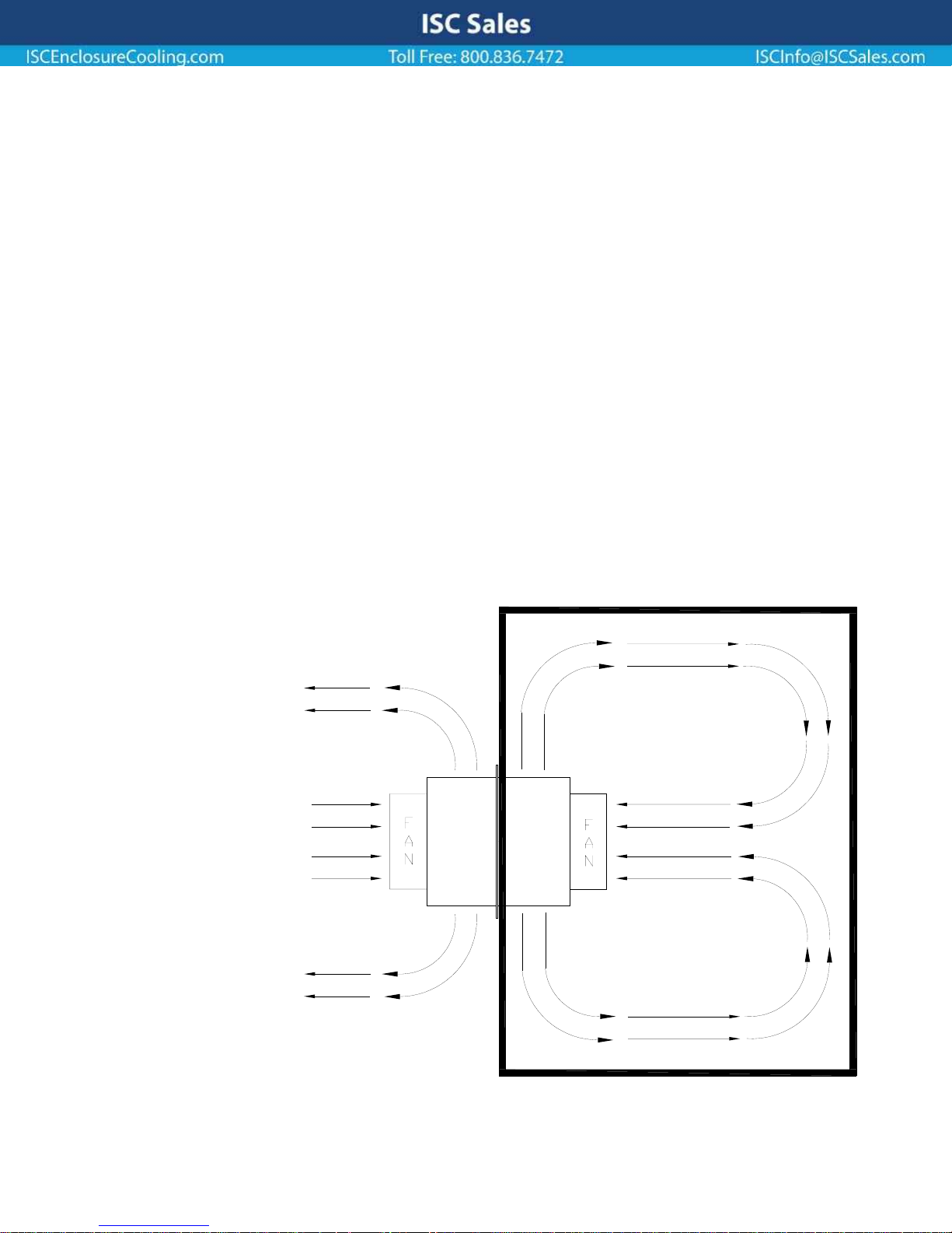
Your ISC Sales, Inc Thermoelectric Air Conditioner operates on this principle so there is no
compressor and no expensive, ozone depleting CFC’s. ISC’s air conditioners use Thermoelectric
“modules” sandwiched between high performance aluminum heat sinks, high CFM axial fans, and a
patented electronic design to “pump” the heat from the inside of your enclosure to the outside,
without exposing your delicate electronics to any outside air or contaminates. See Figure 1.1.
ISC uses only the highest quality components in our air conditioners and you can expect
years of trouble free cooling from these solid-state devices. Every unit we sell is backed by our
one year parts and labor warranty.
AMBIENT AIR
REMOVES HEAT
FROM HOT SIDE
HEAT SINK
HOT
SIDE
HEAT
SINK
FIGURE 1.1
COLD
SIDE
HEAT
SINK
COLD AIR
CIRCULATED
WITHIN THE
ENCLOSURE
COLD AIR
CIRCULATED
WITHIN THE
ENCLOSURE
-800-497-4524 EIC SOLUTIONS, INC. 215-443-5190
1
3

ISC Sales
ISCInfo@ISCSales.comISCEnclosureCooling.com Toll Free: 800.836.7472
2. INSTALLATION
2.1 CHOOSING A LOCATION ON YOUR ENCLOSURE
When choosing a mounting location for your unit, be sure to keep air flows of both the
interior and exterior heatsinks and fans in mind. Adequate clearance between the fans/heatsinks
and nearby surfaces is required for unrestricted air flows which will ensure optimal performance
and long, trouble free operation. The general rule is to allow a minimum of two inches between
the fans or heatsinks and any surface. Refer to figure 1.1 for an air flow diagram.
Other considerations in deciding on a mounting location include; allowing access to
thermostat (this will be inside the enclosure) if frequent adjustments are to be made; allowing
access to the hot side heat sinks (this will be on the outside of the enclosure) for cleaning if the
unit will be used in a harsh, dirty environment.
2.2 ORIENTATION
Your AC unit can be mounted either vertically on the front, rear or side of your enclosure or
horizontally on the top of your enclosure. See Figure 2.1 and 2.2.
Vertically mounted 500 Btu units are always mounted with the exposed heatsink fins at the
bottom and the fans at the top. (Fig. 2.1) Vertical installations often require the use of a
Condensate Drip Pan (part # DP-V) depending on a number of factors including internal enclosure
temperatures and ambient temperatures, humidity levels, quality of enclosure seals, and
frequency of enclosure opening. We strongly recommend the use of a drip pan to protect the
electronics from dripping condensate. (Fig. 2.1)
Mounting the unit with the fins pointing to either side or straight up will cause condensate
to drip in an uncontrolled manner, possibly damaging electronic equipment within the enclosure.
If one of these orientations is the only possible configuration, contact the Engineering Dept. at ISC
for a custom solution.
Horizontally mounted 500 Btu units always require a drip pan (part # DP-142H) to
prevent dripping condensate from damaging electronic equipment. (Fig. 2.2)
In either orientation, issues regarding access should be considered and minimum clearances
must be maintained as outlined in Section 2.1 of this manual.
Fax: 972.964.2755Local: 972.964.2700
4421 Tradition Trail • Plano, Texas 75093
 Loading...