

Page 1

P.1
Assembly Instructions
Please visit our website for the most current instructions, assembly tips, report damage,
or request parts.
Page 2

Instruction Manual
P.2
All rights reserved.
!
IMPORTANT INFORMATION MUST READ BEFORE ASSEMBLING PRODUCT
-
Follow the in f
Do not remove w bed.
-
Use only a mattress which is 75-76" L x 37.5-38.5"W x 9"H on upper bunk, 75"-76" long and 37.5-38.5"W wide on
lower bunk.
Replacement Parts--Replacement parts, including additional guardrails, may be obtained fr
dealers or by contacting us online at our website.
-
Follow the information on the warnings appearing on the upper bunk end structure and on the carton.
DO NOT remove warning label from bed.
-
Always use the recommended size mattress or mattress support, or both, to help prevent the likelihood of
entrapment or falls.
Surface of mattress must be at least 5 in . (127mm) below the upper edge of guardrails. Mattress must
not exceed a maximum thickness of 9 inches.
ormation on the warnings appearing on the upper bunk end structure and on the carton.
arning label from
WARNING
om any of our
-
DO NOT allow children under 6 years of age to use the upper bunk.
-
Periodically check and ensure that the guardrail, ladder, and other components are in their proper position,
freefrom damage, and that all connectors are tight.
-
DO NOT allow horseplay on or under the bed and prohibit jumping on the bed.
-
Always use the ladder for entering and leaving the upper bunk.
-
DO NOT use substitute pars. Contact the manufacturer or dealer for replacement parts.
-
Use of a night light may provide added safety precaution for a child using the upper bunk.
-
Always use guardrails on both long sides of the upper bunk. If the bunk bed will be placed next to the wall,
the guardrail that runs the full length of the bed should be placed against the wall to prevent entrapment
between the bed and wall.
-
The use of water or sleep flotation mattresses is prohibited.
-
STRANGULATION HAZARD - Never attach or hang items to any part of the bunk bed that are not designed
for use with the bed ; for example, but not limited to, hooks, belts and jump ropes.
-
Prohibit more than one person on upper bunk.
-
Keep these instructions for future reference.
Page 3

Parts List
P.3
All rights reserved.
6
4
12
7
12
12
13
13
12
16
8
15
1
14
4
3
3
14
2
5
14
1
3
3
14
2
5
9
11
11
11 1010
Page 4

Hardware List
P.4
A
B
C
D
E
Ø1/4"x15mm
Ø16mm
Ø18mm
Ø5/16"x57mm
Ø1/4"x32mm
Bolt 53
Small washer
Large washer
Bolt
Bolt
58
3
3
6
pcs
pcs
pcs
pcs
pcs
F
G
H
J
Washer
Plastic end cap
Plastic tab lock
Plastic link
6
8
88
42
pcs
pcs
pcs
pcs
The hardware quantities listed above are required for proper assembly.
Some extra hardware may also have been included.
Page 5

Hardware List
P.5
K 22
L 1
M 1
N
M4mm
M5mm
Ø1/4"x57mm
Plastic plug
Hex key
Hex key
Bolt
6
pcs
pc
pc
pcs
The hardware quantities listed above are required for proper assembly.
Some extra hardware may also have been included.
Page 6

P.6
All rights reserved.
Page 7

Step 1
P.7
All rights reserved.
Assembly the four support posts by combining parts (2, 3) and (1), then parts (5, 3) and (4) as shown
in the illustration.
1
3
2
1
3
2
4
3
5
4
3
5
Page 8

Step 2
P.8
All rights reserved.
Secure these parts together using screws (A) and small washers (B). Be sure to tighten firmly with
hex key (L).
A
B
1
3
A
B
4
3
L
2
A
B
1
3
2
5
A
B
4
3
5
Page 9

Using bolt (A) secure small washer (B) to part (14) into parts (1,4) , using bolt (A) secure small washer (B)
to part (14) into parts (2,5) with hex key (L).
Page 10

Step 4
P.10
All rights reserved.
Attach legs (12) to the lower cross bars using screws (A) and small washers (B) as shown in the illustration.
Tighten screws using hex key (L).
12
12
A
B
L
12
8
12
9
Page 11

Step 5
P.11
Attach lower cross bars (8,9) and upper cross bars (15,16) to the end supports in Step 3 using small
washers (B) and screws (A) as shown in the illustration. Ensure the slots on the cross bars are facing
inward as shown in the illustration. Be sure to tighten all screws firmly using hex key (L).
L
A
B
8
15
16
5
4
1
9
2
Page 12

P.12
Step 6
Attach another end supports assembled in Step 3 to bed frame using small washers (B) and screws (A) as
shown in the illustration. Ensure the slots on the cross bars are facing inward as step 5. Be sure to tighten
all screws firmly using hex key (L).
Note: Do not tighten all bolts at this step.
MANUFACTURER
LABEL
L
A
B
9
16
15
SAFETY
LABEL
SAFETY LABEL
4
1
8
2
5
Page 13
P.13
Step 7
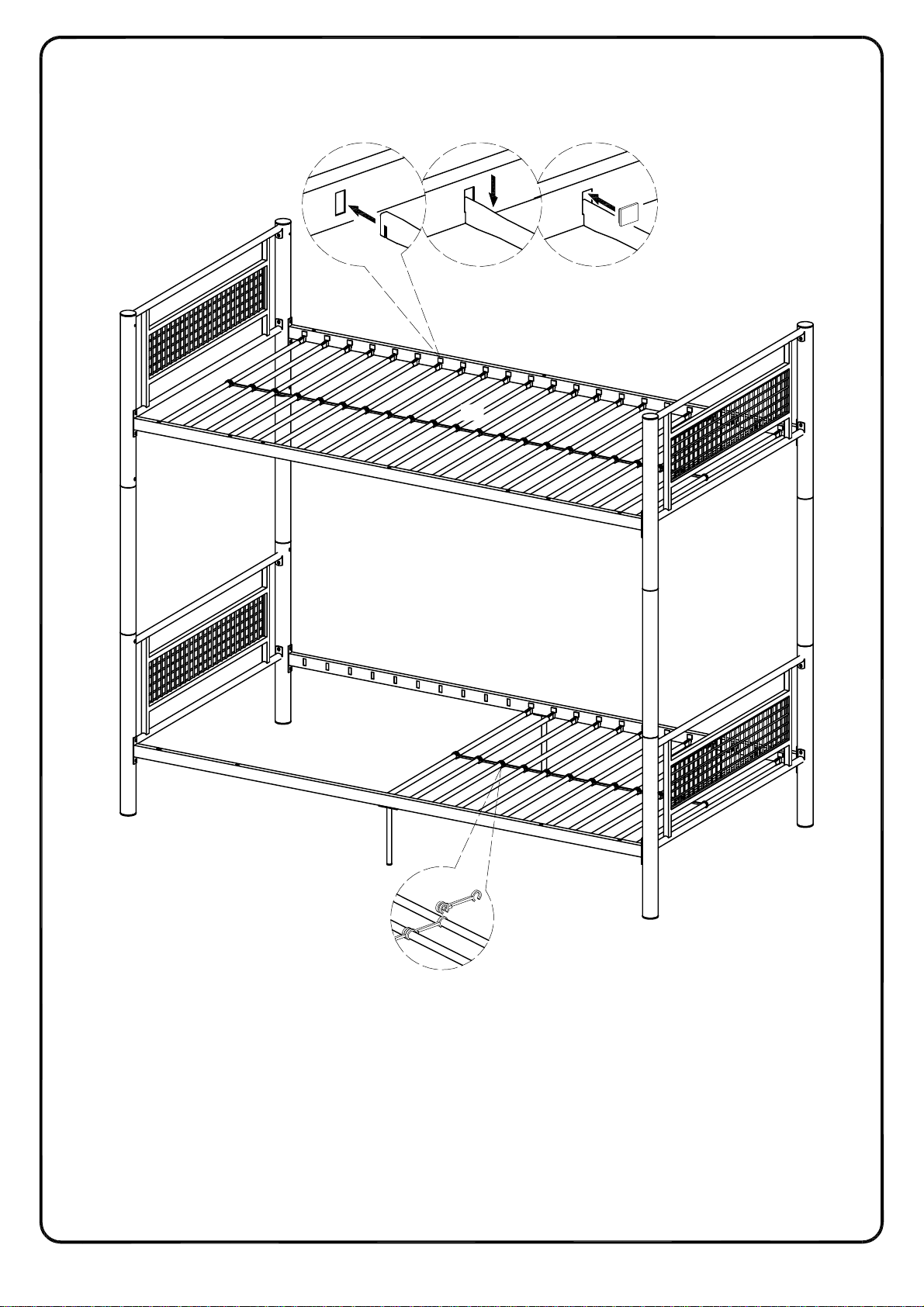
Insert mattress support bars into the slots on the cross bars as shown in the illustration. Snap plastic
tab locks (H) into each slot to lock the mattress support bars in place. Snap plastic links (J) into the middle
of the mattress support bars as shown in the illustration.
H
13
15
13
16
8
9
J
13
Page 14
Step 8
P.14
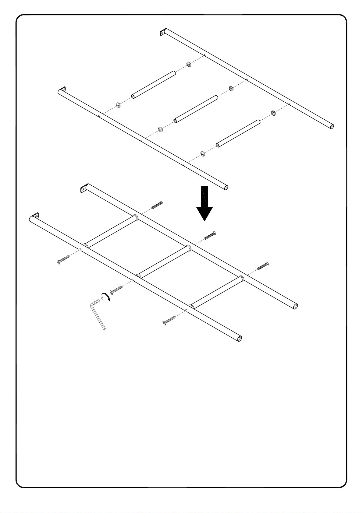
Attach the ladder steps (11) to the ladder support posts (10) using screws (E) and washers (F) as shown
in the illustration.
11
10
F
E
10
F
F
E
F
11
F
F
11
E
E
E
L
E
Page 15

Step 9
P.15
1
B
N
6
B
15
L
N
4
B
N
Attach back upper guardrail (6) to the back frame support beams using bolts (A) and
washers (B) by hex key (L).
Attach guardrail to cross bar (15) using bolts (N) and washers (B) by hex key (L) as shown in
illustration。
Page 16

P.16
All rights reserved.
Step 10A
Attach ladder frame assembly to cross bars (9, 16) using bolts (A, D) and washers (B, C) as shown in
illustration.
Attach open guardrail (7) to upper cross bar using bolts (N) and washers (B), then attach upper guardrail (7)
to support post using bolt (A) and washer (B) as per diagram.
Insert bolt (A) to support (4) using hex key (L).
Then tighten all the bolts.
B
N
7
B
N
L
B
N
C
D
B
A
10
9
C
D
M
10
C
D
Page 17

Step 11A
P.17
All rights reserved.
Put plastic plugs (K) into the holes in the front cross bars as shown in the illustration.
K
K
16
K
K
K
9
Page 18

Step 12A
P.18
All rights reserved.
OPTION A Final
Page 19

Step 10B
All rights reserved.
P.19
Attach ladder frame assembly to the upper cross bar on the right side using bolt (A) and washer (B) on
the left side using bolt (D) and washer (C) as shown in the illustration.
Attach ladder support posts to the lower cross bar using bolt (D) and washers (C) as shown in the
illustration.
Attach open guardrail to the upper cross bar using bolt (N) and washers (B), then attach upper guardrail
to the support post using bolt (A) and washer (B) with hex key (L) as diagram shown.
Insert bolt (A) to support post (1) using hex key (L).
Then tighten all the bolts.
Note: the ladder and open guardrail are on the left side.
7
B
B
C
B
D
A
B
N
N
L
N
10
C
D
10
C
D
M
Page 20

Step 11B
P.20
Place plastic plugs (K) into the holes in the front cross bars (9,16) as shown in the illustration.
K
K
K
16
9
K
K
All rights reserved.
Page 21

Step 12B
All rights reserved.
P.21
OPTION B Final
Page 22

Page 23

Step 14C
All rights reserved.
P.23
Loosen and remove the back upper guardrail with hex key (L) from the bed frame as per diagram.
4
6
1
15
B
N
L
B
N
B
N
Page 24

Step 15C
All rights reserved.
P.24
Loosen and remove the ladder and open guardrail with hex key (L, M) from the bed frame as per diagram.
B
A
L
16
A
M
10
9
Page 25

Step 16C
P.25
Loosen bolts where upper bunk connects with lower bunk .
4
B
A
1
B
A
3
B
A
2
3
4
B
A
L
5
B
A
L
A
B
3
A
B
5
A
A
1
B
3
B
2
Page 26

Step 17C
P.26
All rights reserved.
Lift and separate the bunks.
1
4
1
3
3
5
2
4
3
3
2
5
Page 27

Step 18C
P.27
All rights reserved.
Attach legs (12) to the upper cross bars (15, 16) using bolt (A) and small washers (B) as shown in the
illustration. Tighten bolts using hex key (L). Attach plastic end caps (G) as shown in the illustration.
L
A
G
G
1
16
B
A
12
B
4
G
4
15
G
12
B
A
G
1
G
G
5
G
2
5
2
Page 28

Place plastic plugs (K) into the holes in the front cross bars as shown in the illustration. Insert bolt (A) to
support (1, 2, 4, 5) by using hex key (L).
Page 29

P.29
All rights reserved.
Step 20C
OPTION C Final
 Loading...