

Page 1

DATE: 04/10/20011 DOC.SIE10110 REV.6
T2000 TEST SET
for testing CT’s, PT’s,
primary injections and relay tests
www.GlobalTestSupply.com
Find Quality Products Online at: [email protected]
Page 2

DOC. SIE10110 Rev. 6 Page 3 of33
1 INTRODUCTION ....................................................................................................................................................... 4
2 APPLICABLE STANDARDS ...................................................................................................................................... 7
3 CHARACTERISTICS ................................................................................................................................................ 8
3.1 FOREWORD ............................................................................................................................................................... 8
3.2 MAIN GENERATOR .................................................................................................................................................... 8
3.2.1 High AC current ............................................................................................................................................... 8
3.2.2 Low AC current ................................................................................................................................................. 8
3.2.3 Low DC current ................................................................................................................................................ 9
3.2.4 Current impulses ............................................................................................................................................... 9
3.2.5 High AC voltage .............................................................................................................................................. 10
3.2.6 Low AC voltage ............................................................................................................................................... 10
3.2.7 Other features of main outputs ....................................................................................................................... 10
3.3 AUXILIARY CONTACT .............................................................................................................................................. 10
3.4 TIMER ..................................................................................................................................................................... 11
3.5 OUTPUTS MEASUREMENT......................................................................................................................................... 11
3.5.1 Current and voltage ........................................................................................................................................ 11
3.5.2 Phase angle ..................................................................................................................................................... 13
3.5.3 Other measurements ....................................................................................................................................... 14
3.6 EXTERNAL INPUTS MEASUREMENT ......................................................................................................................... 14
3.6.1 Current measurement ..................................................................................................................................... 14
3.6.2 Voltage measurement ...................................................................................................................................... 15
3.6.3 Other measurements ....................................................................................................................................... 15
3.7 DISPLAY .................................................................................................................................................................. 16
3.8 TEST CONTROL ........................................................................................................................................................ 16
3.8.1 Relay selection ................................................................................................................................................. 16
3.8.2 Transformers selection ................................................................................................................................... 16
3.9 MENU SELECTIONS .................................................................................................................................................. 17
3.9.1 Relay selection ................................................................................................................................................. 17
3.9.2 Transformers selection ................................................................................................................................... 20
3.10 CONNECTION CABLES ........................................................................................................................................... 22
3.11 OTHER CHARACTERISTICS ..................................................................................................................................... 23
3.12 OPTIONS ................................................................................................................................................................ 23
3.12.1 Power supply code PII20110 ........................................................................................................................ 23
3.12.2 Optional high voltage output 1200 V; codes PII30110 (supply 230 V) or PII40110 (supply 110 V) ......... 24
3.12.3 Model T2000E, code PII50110 .................................................................................................................... 24
3.12.4 Transit cases .................................................................................................................................................. 24
3.12.5 Current clamp code PII16102 ...................................................................................................................... 25
3.12.6 Thermal printer PII14102 ............................................................................................................................ 26
3.12.7 BU2000: very high AC current boosters ...................................................................................................... 26
3.12.8 High I DC module PII13102 ........................................................................................................................ 30
3.12.9 SU3000 Safety device for the line impedance measurement, code ZII26102 ............................................ 30
3.12.10 FT/1000 current filter, code PII16093 ....................................................................................................... 31
3.12.11 Earth resistance and resistivity test kit, code PII19102 ............................................................................. 31
4 PROTECTIONS ........................................................................................................................................................ 33
www.GlobalTestSupply.com
Find Quality Products Online at: [email protected]
Page 3

DOC. SIE10110 Rev. 6 Page 4 of33
1 I NTRODUCTION
T2000 allows performing all tests on current and voltage transformers, and of some protection
relays. The following table lists the tests that can be performed on CT and VT.
N.
TEST
OF
TEST DESCRIPTION
1
CT
Ratio, Voltage mode
2
CT
Ratio, polarity and burden
3
CT
Burden; secondary side
4
CT
Excitation curve
5
CT
Winding or burden resistance
6
CT
Voltage withstand
7
CT
Polarity by impulses
8
VT
Ratio; polarity
9
VT
Burden, secondary side
10
VT
Ratio, electronic transformers
11
VT
Voltage withstand
12
VT
Secondary over-current protection
13
PT
Ratio per TAP
14
PT
Resistance of Tap Changer contacts
15
PT
Tap Changer dynamic resistance test
16 R Ground resistance and resistivity
Tests are performed in accordance with the following IEC standards: EN 60044-1; EN 60044-2; EN
60044-5; EN 60044-7; EN 60044-8; EN 60076-1, and also in accordance with ANSI/IEEE
C57.13.1.
The following table lists the tests that can be performed on protection relays (FW revision 1.40).
Type of relay
IEEE code
- Thermal
26
- Over/under-voltage
27 - 59
- Under current
37
- Instantaneous overcurrent
50
- Ground fault
50N
- Timed overcurrent
51
- Circuit breaker
52
- Automatic reclose
79
- Tripping relay
94
- Timers
In addition to the above, T2000 can test the impedance and coupling coefficient of overhead lines.
With external options, T2000 can test:
. With the High IDC module, up to 400 A: contact resistances, in the micro-Ohm range;
. With the current booster: primary tests, up to 2000 A; with the very high current booster option, up
to 4000 A.
The basic T2000 function is to generate current and voltages, as requested by the type of test to be
performed, that is selected on the LCD screen by means of the multi-function knob. Test results are
kept in memory, and can be transferred to a PC at a later time, along with settings.
www.GlobalTestSupply.com
Find Quality Products Online at: [email protected]
Page 4
DOC. SIE10110 Rev. 6 Page 5 of33
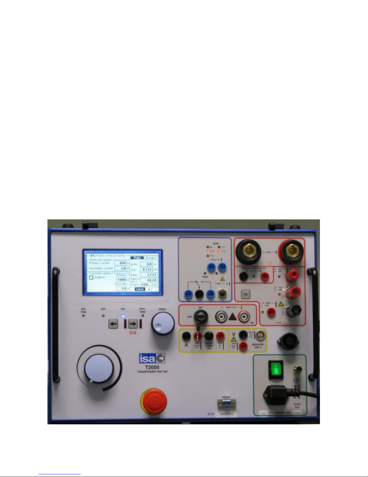
The instrument contains a generator, with six outputs: High AC current; Low AC current; Low DC
current; Current impulses; High AC voltage; Low AC voltage.
The selected output is adjustable and metered on the large, graphic LCD display. With the multipurpose knob and the LCD display it is possible to enter the MENU mode, that allows to set many
functions, that make T2000 a very powerful testing device, with manual and semi-automatic testing
capabilities, and with the possibility to transfer test results to a PC via the RS232 interface. These
results can be recorded, displayed and analysed by the powerful TDMS software, which operates
with all WINDOWS versions.
The ease of operation has been the first goal of T2000: this is why the LCD is graphic, and so large.
With it, the dialogue in MENU mode is made easy. Besides, all T2000 outputs relevant to the
selected test are continuously measured, and output values are displayed, with no extra effort to the
operator. Also the show waveform feature can be of help: any doubt about strange measurements,
distortion and so on can be solved.
Additional feature: two meters, current and voltage, with independent inputs, and with High and
Low inputs each, allow measuring CT or VT outputs or any other source.
The instrument is housed in a transportable aluminium box, which is provided with removable
cover and handles for ease of transportation. The picture shows T2000 without the protection
cover.
The following is the list of available options:
1. Power supply 110 V, to be specified at order;
www.GlobalTestSupply.com
Find Quality Products Online at: [email protected]
Page 5

DOC. SIE10110 Rev. 6 Page 6 of33
2. Optional high voltage 1200 V, instead of 3000 V (better choice for 5 A rated CT’s), to be
specified at order;
3. T2000E, model with high voltage at 1200 V and the high current output power boosted to
850 VA;
4. Transit cases: moulded plastic or aluminium;
5. Secondary current clamp meter;
6. Local thermal printer;
7. BU2000: very high current booster, for currents up to 4000 A AC, for primary injection tests;
8. High IDC current generator module, up to 400 A DC, for the measurement of joint
resistances;
9. SU3000: protection module for line impedance measurement.
10. FT/100: filter for highly inductive loads, that tend to distort the current waveform.
11. Cables and electrodes kit for the measurement of plant earth resistance, and soil resistivity.
NOTE: WINDOWS is a trademark of MICROSOFT inc.
www.GlobalTestSupply.com
Find Quality Products Online at: [email protected]
Page 6

DOC. SIE10110 Rev. 6 Page 7 of33
2 APPLICABLE STANDARDS
The test set conforms to the EEC directives regarding Electromagnetic Compatibility and Low
Voltage instruments.
A) Electromagnetic Compatibility:
Directive no. 2004/108/EC. Applicable Standard : EN61326-1 + A1 + A2.
EMISSION
- EN 61000-3-2: Harmonic content of power supply. Acceptable limits: basic.
- EN 61000-3-3: Limitation of voltage fluctuations and flicker. Acceptable limits: basic.
- CISPR16 (EN 55011 class A): Limits and measurement methods of radio-electric disturbances for
industrial, medical and scientific instruments at radio-electric frequencies.
Acceptable limits for conducted emission:
. 0.15-0.5 MHz: 79 dB pk; 66 dB avg.
. 0.5-5 MHz: 73 dB pk; 60 dB avg.
. 5-30 MHz: 73 dB pk; 60 dB avg.
Acceptable limits for radiated emission:
. 30-230 MHz: 40 dB (30 m)
. 230-1000 MHz: 47 dB (30 m)
IMMUNITY
- EN 61000-4-2: Immunity tests for ESD. Test values: 8 kV in air; 4 kV in contact.
- EN 61000-4-3; Immunity tests for radio frequency interference. Test values (f= 900 5 MHz):
field 10 V/m, modulated AM 80%; 1 kHz
- EN 61000-4-4; Immunity tests for high speed transients (burst). Test values: 2 kV peak; 5/50 ns.
- EN 61000-4-5; Immunity tests for surge. Test values: 1 kV peak differential mode; 2 kV peak
common mode; 1.2/50 us.
- EN 61000-4-6: immunity to low-voltage sinusoidal waveform. Test values: 0.15-80 MHz, 10
Vrms, 80% AM 1 kHz.
- EN 61000-4-8: Immunity tests for low frequency magnetic fields. Test values: 30 Arms/m.
- EN 61000-4-11: Immunity test for power supply dops. Test value: 1 cycle; 100% drop.
B) Low Voltage Directive:
- - Directive n. 2006/95/EC.
- Applicable standard: EN 61010-1. In particular, for a pollution degree 2: dielectric rigidity 1.4 kV
AC, 1 minute. The rigidity is 4600 V AC 1 minute between the high voltage output and the rest of
inputs and outputs.
- Inputs/outputs protection: IP 2X, per IEC 60529, for all but high voltage outputs; IP4X for high
voltage outputs.
- Operating temperature: 0 to 50 °C; storage: -20 °C to 70 °C.
- Relative humidity : 5 - 95%, without condensing.
- Vibration: IEC 68-2-6 (20 m/s^2 at 10 – 150 Hz);
- Shock: IEC 68-2-27 (15 g; 11 ms; half-sine).
- Altitude: less than 2000 m.
www.GlobalTestSupply.com
Find Quality Products Online at: [email protected]
Page 7

DOC. SIE10110 Rev. 6 Page 8 of33
3 CHARACTERISTICS
3.1 FOREWORD
T2000 incorporates a generator with six outputs. When an output is generated, also all other outputs
are present at sockets, unless for the high AC voltage, that can be generated only if it is selected and
confirmed by a key.
The generator is made of a variable transformer followed by a transformer. The variable
transformer does not reach the zero position; so, when you are adjusting the output current on a low
burden, the minimum current can be up to 5% of the range. If this is a problem on relay tests, select
the 60 VA power: the current is reduced to one fifth.
3.2 MAIN GENERATOR
The main generator has six outputs: High AC current; Low AC current; Low DC current; Current
impulses; High AC voltage; Low AC voltage. Output adjustment is performed via a knob. The
following specification applies to the separate usage of these outputs.
3.2.1 High AC current
- Output characteristics: see table below.
CURRENT
OUTPUT
A
OUTPUT
POWER
VA
LOAD
TIME
s
RECOVERY
TIME
min
100
600
STEADY
-
150
800
15 min
30
200
1000
4 min
15
400
1600
15
5
600
2000 5 3
800
2000 1 2
- Connection: two high power sockets, with safety protections.
3.2.2 Low AC current
- Output characteristics: see table below.
1) NOMINAL POWER 300 VA
www.GlobalTestSupply.com
Find Quality Products Online at: [email protected]
Page 8
DOC. SIE10110 Rev. 6 Page 9 of33
RANGE
A AC
CURRENT
OUTPUT
A
OUTPUT
POWER
VA
LOAD
TIME
s
RECOVERY
TIME
min
40
12
300
STEADY
-
18 15 min
30
24 4 min
15
36
800
15
5
48 5
3
60
1000 1 2
10
5
400
STEADY
-
7.5 15 min
30
10
800
60
15
15 30
10
20
1000
15
5
2) NOMINAL POWER 60 VA
RANGE
A AC
CURRENT
OUTPUT
A
OUTPUT
POWER
VA
MAX. TEST
DURATION
s
RECOVERY
TIME
s
40
12
60
STEADY
-
17 10 min
30
23 60
10
36 1
2
10
5
60
STEADY
- 6
10 min
45 7
60
2
10 1,5
2
- Power selection: via menu.
- Connection: three high current safety sockets.
3.2.3 Low DC current
- Output characteristics: see table below.
CURRENT
OUTPUT
A
LOAD
RESIST.
Ohm
OUTPUT
POWER
VA
LOAD
TIME
min
RECOVERY
TIME
min
10 0 0
STEADY
- 3 2
18
STEADY
- 1 8 8 STEADY
-
- Type of DC voltage: unregulated, via diode bridge rectifier and capacitor, plus limiting resistor.
- Output connection: two safety sockets.
3.2.4 Current impulses
Current impulses are only positive; this solves the problem of the ambiguity of secondary impulse
polarity that is found if a DC voltage is used.
www.GlobalTestSupply.com
Find Quality Products Online at: [email protected]
Page 9
DOC. SIE10110 Rev. 6 Page 10 of33
- Type of waveform: R-C discharge; polarity: positive.
- Current range: from 0 to 10 A peak.
- Repetition rate: a pulse every 3 s.
- Output connection: two safety sockets.
3.2.5 High AC voltage
- Type of generator: variable transformer and high voltage transformer.
- Output characteristics: see table below.
VOLTAGE
OUTPUT
V
CURRENT
OUTPUT
A
OUTPUT
POWER
VA
LOAD
TIME
Min
RECOVERY
TIME
min
3000
2500
0.2
0.6
600
1500
STEADY
1 - 8
- Output connection: two H.V. safety sockets.
3.2.6 Low AC voltage
- The AC voltage is isolated from the high AC current.
- AC voltage range: 250 V.
- Available power and duty cycle: see table below.
- Connection: two safety banana sockets.
RANGE
V AC
VOLTAGE
OUTPUT
V
OUTPUT
POWER
VA
LOAD
TIME
min
RECOVERY
TIME
min
250
250
125
STEADY
-
220
250
3
9
3.2.7 Other features of main outputs
- Zero crossing control. Main AC outputs are generated and stopped as the output waveform is zero.
This implies that in mode ON+TIME the output drops to zero with a delay from 0 to one cycle after
STOP is detected.
- Over-current alarm message.
- Thermal protection: by NTC. The operator is alerted by a message.
- Output adjustment: from less than 5% to 100% of the output.
- Output measurement. The used output is software selected; the selected socket is confirmed by a
light.
3.3 AUXILIARY CONTACT
- Possibility to delay the auxiliary contact switch with respect to test start. Delay range: from 0 to
99.99 s.
- Contacts range: 5 A; 250 V AC; 120 V DC
www.GlobalTestSupply.com
Find Quality Products Online at: [email protected]
Page 10
DOC. SIE10110 Rev. 6 Page 11 of33
3.4 TIMER
The electronic digital timer has a fully automatic stop, both for make and break of the input, that
can be either a clean contact or a contact under voltage. All selections are menu-driven via the
multi-function knob.
- Characteristics of Stop input:
.. Input connection: two banana sockets;
.. Input may be selected as Normal Open or Normal Close. It is possible to select timer stop on
input level transition;
.. Type of input: either dry or under voltage; selection via the multi-function knob. Maximum input:
250V AC or 275 V DC;
.. With dry input selection, the wetting voltage is 24 V; the test current is 3 mA nominal;
.. With voltage input selection, two thresholds can be selected: 24 V or 80 V;
.. Selections are displayed on the front panel by 5 dedicated lights;
.. When the input is closed or with voltage an LED turns on;
.. When the relay intervenes the TRIP light turns on;
.. Wrong selection protection. If voltage is applied when clean input is selected, input circuits are
not damaged;
.. Timer start: as the fault is generated.
- Available measurement: elapsed time between test start and STOP input.
- Time can be metered as seconds or cycles. Metering range, in seconds: see table.
Range
Resolution
Accuracy
From 0 to 9.999 s
1 ms
± (1 ms + 0.005%)
From 10.00 to 99.99 s
10 ms
± (10 ms + 0.005%)
From 100.0 to 999.9 s
100 ms
± (100 ms + 0.005%)
From 1000 to 9999 s
1 s
± (1 s + 0.005%)
. Metering range, in cycles, selectable at 50 Hz or at 60 Hz.
Range
Resolution
Accuracy
From 0 to 1,000
(Equal to 19.998 s @ 50 Hz;
16.665 s @ 60 Hz)
0.1 cycles
± (0.1 cycles + 0.005%)
From 1000 to 499,998.5 cycles @ 50 Hz;
From 1000 to 599,998 cycles @ 60 Hz
(Equal to 9999 s)
1 cycle
± (1 cycle + 0.005%)
- Display reset: automatic, at test start.
3.5 OUTPUTS MEASUREMENT
3.5.1 Current and voltage
- The displayed measurements follow the test selection.
- Type of measurement: true rms for AC outputs; average for DC outputs.
- Readings, resolution and accuracy: see table. Note that the available ranges can be greater than the
maximum value of the output to which the load is connected: this means that higher values can be
www.GlobalTestSupply.com
Find Quality Products Online at: [email protected]
Page 11

DOC. SIE10110 Rev. 6 Page 12 of33
measured without saturation. For example, on the 800 A output the measuring range is up to 999 A.
Actually, the test set will not generate more than 800 A, as the test is stopped by the software, that
indicates overload, and on the display currents more than 800 A will not be shown.
www.GlobalTestSupply.com
Find Quality Products Online at: [email protected]
Page 12

DOC. SIE10110 Rev. 6 Page 13 of33
OUTPUT
RANGE
RESOLUTION
ACCURACY
HIGH AC CURRENT
19.99 A
20 mA
± (0.5% + 50 mA)
199.9 A
200 mA
± (0.5% + 400 mA)
999 A
1 A
± (0.5% + 1 A)
LOW AC CURRENT;
10 A
1.999 A
1 mA
± (0.5% + 5 mA)
19.99 A
10 mA
± (0.5% + 20 mA)
LOW AC CURRENT;
40 A
7.999 A
4 mA
± (0.5% + 20 mA)
79.99 A
40 mA
± (0.5% + 80 mA)
VOLTAGE OF LOW
AC CURRENT
19.99 V
20 mV
± (0.5% + 50 mV)
99.9 V
100 mV
± (0.5% + 200 mV)
HIGH AC VOLTAGE;
3000 V
199.9 V
200 mV
± (0.5% + 0.5 V)
1999 V
2 V
± (0.5% + 4 V)
2999 V
3 V
± (0.5% + 6 V)
CURRENT OF HIGH
AC VOLTAGE
19.99 mA
50 uA
± (0.5% + 200 uA)
199.9 mA
200 uA
± (0.5% + 500 uA)
0.999 A
1 mA
± (0.5% + 2 mA)
LOW AC VOLTAGE
250 V AC
19.99 V
20 mV
± (0.5% + 50 mV)
199.9 V
200 mV
± (0.5% + 400 mV)
299.9 V
300 mV
± (0.5% + 600 mV)
CURRENT OF LOW
AC VOLTAGE
19.99 mA
20 uA
± (0.5% + 50 uA)
199.9 mA
200 uA
± (0.5% + 400 uA)
1.999 A
2 mA
± (0.5% + 4 mA)
LOW DC CURRENT
199.9 mA
100 uA
± (0.5% + 200 uA)
1.999 A
1 mA
± (0.5% + 2 mA)
19.99 A
10 mA
± (0.5% + 20 mA)
I IMPULSES
19.9 A
0.1 A
± (5% + 0.5 A)
NOTES:
- The change range is the actual value at which the range is changed. This avoids saturation
problems when we have to measure fast-changing values.
- Metering temperature coefficient: ± 0,05%/°C of the value ± 0,02%/°C of the range.
3.5.2 Phase angle
- Readings, resolution and accuracy: see table.
MEASUREMENT
RANGE
RESOLUTION
ACCURACY
PHASE
0 - 360
1°
1° ± 1 DIGIT *
* Specified accuracy applies to outputs greater than 10% of the selected range.
- Phase angle temperature coefficient: ± 1 ppM/°C of the value.
www.GlobalTestSupply.com
Find Quality Products Online at: [email protected]
Page 13
DOC. SIE10110 Rev. 6 Page 14 of33
3.5.3 Other measurements
Starting from the above measurements, the test set can compute derived measurements, according
to test selection.
The following is the list of available measurements. For all of them the following range and
resolution applies; the accuracy is the sum of voltage, current and possibly angle accuracy.
N.
PARAMETER , AC outputs
DERIVED
FROM
FORMULA
UNITS
1
RATIO, CT or VT or PT
I out, I in or
Vout, V in
R = I out / I in
R = V out / V in
- 2 POLARITY, CT or VT or PT
φ I out, I in or
φ Vout, V in
OK = φ < 10°
3
BURDEN, CT
Vout;Iout
VA= IN^2*Vout/Iout
VA
4
VOLTAGE AND CURRENT KNEES
Vout, Iout
VKm, IKm:
according to
standards
V, A
5
Resistance
Iout, Vout
R = Vout/Iout
Ohm
For the CT, VT and PT ratio measurement, the following applies.
- Range: 9999;
- Accuracy: 0.5 typical; 1% maximum.
For the polarity test, the phase shift between the two parameters is tested. Answer is OK if phase
shift is less than 10°.
For the resistance, we measure up to 250 Ohm at 50 mA; the accuracy is: 0.5 typical; 1%
maximum.
3.6 EXTERNAL INPUTS MEASUREMENT
- It is possible to meter the current and the voltage of an external (or internal) generator.
- Input connection: by four safety sockets; three for current and two for voltage.
- Metering circuits are isolated between them and from the rest of the instrument.
3.6.1 Current measurement
- Two inputs: 20 mA or 10 A AC.
- Range, resolution, accuracy: see tables below.
RANGE 20 mA
RESOLUTION
ACCURACY
25 mA DC
0.1 mA
± (0.5% + 0.2 mA)
RANGE 10 A
RESOLUTION
ACCURACY
1.999 A AC
1 mA
± (0.5% + 4 mA)
9.99 A AC
10 mA
± (0.5% + 40 mA)
www.GlobalTestSupply.com
Find Quality Products Online at: [email protected]
Page 14
DOC. SIE10110 Rev. 6 Page 15 of33
- Metering temperature coefficient: ± 0,05%/°C of the value ± 0,02%/°C of the range.
- Possibility to display the current waveform.
3.6.2 Voltage measurement
- Two inputs: 10 V or 600 V, AC or DC
- Range, resolution and accuracy: see tables below.
RANGE 10 V
RESOLUTION
ACCURACY
0.199 V AC
1 mV
± (0.5% + 2 mV)
1.999 V AC
2 mV
± (0.5% + 10 mV)
9.999 V AC
10 mV
± (0.5% + 50 mV)
RANGE 600 V
RESOLUTION
ACCURACY
19.99 V AC
10 mV
± (0.5% + 40 mV)
199.9 V AC
50 mV
± (0.5% + 400 mV)
599.9 V AC
300 mV
± (0.5% + 1000 mV)
19.99 V DC
10 mV
± (0.5% + 40 mV)
199.9 V DC
50 mV
± (0.5% + 400 mV)
599.9 V DC
300 mV
± (0.5% + 1000 mV)
- Metering temperature coefficient: ± 0,05%/°C of the value ± 0,02%/°C of the range.
- Possibility to display the voltage waveform.
3.6.3 Other measurements
With relay selection, it is possible to compute measurements on external inputs. In this instance,
measurements available depend upon the AC or DC selection for both inputs (no measurement for
mixed selections).
N.
PARAMETER , AC INPUTS
DERIVED
FROM
FORMULA
UNITS
1
ACTIVE POWER, P
Iext, Vext; φ
P= I*V*cos (φ)
W
REACTIVE POWER, Q
Iext, Vext; φ
Q= -I*V*sin(φ)
VAr
2
APPARENT POWER, S
Iext, Vext
S= I*V
VA
POWER FACTOR, p.f.
φ
p.f. = cos(φ)
- 3 IMPEDANCE, Z and φ
Iext, Vext, φ
Z = V/I
Ohm, °
4
ACTIVE IMPEDANCE COMP., R
Iext, Vext; φ
R = Z* cos(φ)
Ohm
REACTIVE IMPEDANCE COMP., X
Iext, Vext; φ
X = Z* sin(φ)
Ohm
5
FREQUENCY, F
Vext
-
Hz
The angle measurement accuracy is ± 1° ± 1 digit. This accuracy applies to inputs greater than 10%
of the input range, and for frequencies of 50 ± 0,5 Hz, and 60 ± 0,6 Hz. Temperature coefficient: ±
1 ppM/°C of the value.
The frequency measurement accuracy is ± 1 mHz ± 1 digit. This accuracy applies to inputs greater
than 10% of the input range, and for frequencies of 50 ± 0,5 Hz, and 60 ± 0,6 Hz. Temperature
coefficient: ± 1 ppM/°C of the value.
www.GlobalTestSupply.com
Find Quality Products Online at: [email protected]
Page 15

DOC. SIE10110 Rev. 6 Page 16 of33
For other parameters, the accuracy is the sum of voltage, current and angle accuracies, as
applicable.
PARAMETER , DC INPUTS
DERIVED
FROM
FORMULA
UNITS
POWER, W
Iext, Vext
P= I*V
W
RESISTANCE, R
Iext, Vext
R = V/I
Ohm
With CT or VT or PT selection, the measurement follows the selected test.
3.7 DISPLAY
The graphical display has the following main features:
- pixels: 240x128
- backlight color: white
- LCD type: FSTN
- View area: 135x80 mm.
3.8 TEST CONTROL
3.8.1 Relay selection
- Manual start control:
. OFF: main outputs are not generated; Vac aux is generated, and it can be either the prefault value or the fault value, according to selections; VDC aux is generated.
. ON: main outputs are generated; Vac aux has the fault value. In this situation it is possible
to verify and memorize the relay threshold, both trip and reset.
. From OFF to ON + time: main outputs are generated and the timer starts according to
selections; as STOP is sensed, main outputs are removed and the elapsed time displayed and
test result can be memorized.
. From ON to OFF + time: main outputs are removed the timer starts according to selections;
as STOP is sensed, the elapsed time is displayed and test result can be memorized.
- Other test control selections:
. Momentary: in ON mode, main outputs are generated until the push-button is pressed;
. Timed: main outputs are generated for the programmed maximum time;
. External. This mode allows for the synchronization of more T3000;
. OFF delay: fault parameters can be maintained for the specified time after relay trips: this
allows simulating the circuit breaker delay.
- Save selections:
. Automatic saving.
. Test data can be saved after confirmation. After relay trip, pressing the multi-function knob
it is possible to save the test result.
3.8.2 Transformers selection
- The LED by the side of the selected output turns on: this helps the operator not to mistake test
connections.
www.GlobalTestSupply.com
Find Quality Products Online at: [email protected]
Page 16

DOC. SIE10110 Rev. 6 Page 17 of33
- Test control: by two push-buttons: OFF an ON.
- OFF: all outputs are not generated.
- ON: outputs are generated, according to the selected test. During ON, the selected parameter is
adjusted to the desired value. The OK signal blinks 3 s after the parameter did not change any more,
and tells the operator that the test is finished. At this moment outputs are cut off, and the operator is
warned to set back to zero the adjustment knob.
3.9 MENU SELECTIONS
The following is the list of features which are menu selected. The menu is operated by means of the
control knob marked MENU, which incorporates a switch. The menu is entered pressing the knob
and selecting the item moving the knob. Once the item has been found and programmed, pressing
the arrow the menu moves back of one step, so that other programming can be performed; else,
selecting ESC the menu returns to the main window.
The first selection is RELAY or TRANSFORMERS; after this, the corresponding selections are
accessible.
Any setting can be saved to and recalled from the memory. Up to 10 settings can be stored and
recalled; setting no. 0 is the default one, and pops up at power-on. Settings are permanently stored
in the memory; new settings can be written to the same address after confirmation. For normal
mode operation it is possible to recall the standard setting, which cannot be modified.
During the test, test results can be stored in the memory (up to 500 results may be stored). At the
end of test, settings and test results can be transmitted to a PC provided with TDMS. The software
allows saving test results, examining them and so on. The specification of TDMS is given in a
separate document.
When the PC is connected, settings can also be created and transferred into T2000 using TDMS.
The following table summarizes all tests and the corresponding performances.
3.9.1 Relay selection
During menu selections the display shows output measurements, in reduced format. After
confirmation, menu messages disappear, and measurements are displayed in the standard format.
The flux diagram of menu selections can be found in Appendix 1.
www.GlobalTestSupply.com
Find Quality Products Online at: [email protected]
Page 17

DOC. SIE10110 Rev. 6 Page 18 of33
LEVEL1
LEVEL 2
LEVEL 3
LEV. 4
FUNCTION
TEST
CONTROL
Test
mode
Normal (default)
Measures the time delay from test START to
STOP (internal, external).
Trip + pulse time
Measures the time delay from test START to
STOP (internal, external), and the duration of
STOP.
Fault
injection
Maintained (default)
Generation lasts indefinitely
Momentary
Generation lasts until the ON button is pressed
Timed
Max time
Generation lasts for the pre-set time duration. Max
time 999 s.
OFF
delay
T delay
The main output OFF is delayed by the set amount
of time or cycles.
Output
power
300 VA (default) –
60 VA
Selection of full (300 VA) or reduced (60 VA)
power
Save
Don’t save (default)
Test data are not saved
Automatic, at trip
As relay trips data are saved to the next memory
location
Confirm, at trip
As relay trips data can be saved, after confirmation
Manual
When selected, generated values are saved.
Auxiliary
contact
Timing
Sets the contact timing with respect to test start
www.GlobalTestSupply.com
Find Quality Products Online at: [email protected]
Page 18

DOC. SIE10110 Rev. 6 Page 19 of33
LEVEL
1
LEVEL
2
LEVEL
3
LEVEL
4
FUNCTION
TIMER
STOP
Stop
INT
Timer stops when the current of the main generator
is interrupted.
EXT
(def.t)
NO-NCEDGE (def.t)
Timer stops when the STOP input is detected.
External STOP input Normally Open or Normally
Closed or Both (EDGE).
CLEAN-24 V
– 80 V
Timer stops when the STOP input is detected.
External STOP input without or with voltage. If
with voltage, two voltage thresholds are available:
24 or 80 V.
Timer
s (default)
Time duration metered in seconds
cycles
Time duration metered in cycles
LEVEL 1
LEV. 2
LEVEL 3
LEVEL 4
FUNCTION
METERS
Internal
Units of I
Normal
If selected, current values are displayed
in A.
I/IN
IN
If selected, displayed values are defined
as I/IN, that can be defined.
Units of V
Normal
If selected, voltage values are displayed
in V.
V/VN
VN
If selected, displayed values are defined
as V/VN (phase voltage), that can be
defined.
External
I
Enabled
AC (default) - DC
With selection AC the meter performs
the true rms measurement; with
selection DC, the measurement is
performed on the average.
10A – 20 mA
Selects the current input socket
Waveform
If selected, the current waveform is
displayed
External
V
Enabled
AC (default) - DC
With selection AC the meter performs
the true rms measurement; with
selection DC, the measurement is
performed on the average.
Shunt : 1 – 1000 mOhm
If the voltage is coming from a current
dropping on a shunt, specifying the
shunt value the current is displayed;
default 100 mOhm.
Waveform
If selected, the voltage waveform is
displayed
www.GlobalTestSupply.com
Find Quality Products Online at: [email protected]
Page 19

DOC. SIE10110 Rev. 6 Page 20 of33
LEVEL1
LEVEL
2
LEVEL 3
FUNCTION
METERS
(continued)
Other
external
None (default)
No extra measurement displayed
Active power
P; W
Reactive power (AC)
Q; VAr
Impedance module
Z, Ohm
Impedance argument
φ, °
Active impedance
component
R, Ohm
Reactive impedance
component (AC)
X, Ohm
Phase, I (AC)
φ, Vmain-Iext; reference Vaux
Phase, V (AC)
φ, Vmain-Vext; reference Vaux
Apparent power (AC)
S; VA
Power factor
p.f. = cos φ(V-I)
Frequency of V (AC)
f, Hz
LEVEL1
LEVEL 2
LEVEL 3
LEVEL 4
FUNCTION
RESULTS
Display
Display selected result
Delete
Delete selected result
Print
Print selected result
CONFIGURATION
Settings
Save to address
1..10
Saves current settings to X
Restore address
1..10
Restores settings from X
Restore default
1..10
Restores default settings
Language
To be specified at order
Display
Speed
Slow
The displayed value is refreshed every
1000 ms
Fast
The displayed value is refreshed every
300 ms
Hold mode
Hold trip
As relay trips, test data measured 4
periods before trip are held.
Hold min
As relay trips, the minimum value
within 0.5 s is held.
Hold max
As relay trips, the maximum value
within 0.5 s is held.
Note: measurements marked AC apply only if both inputs are selected as alternate current.
3.9.2 Transformers selection
With this selection, you can choose the desired type of test. After entering the selection, the
operator can input the relevant parameters, still by using the multi-function knob: turning it allows
changing the parameter; pressing it makes it possible to go to next parameter.
Once all parameters are set, it is possible to start the test and execute it. Test time is kept to the
minimum to avoid the excess of heating. The following table summarizes all tests and the
corresponding performances.
www.GlobalTestSupply.com
Find Quality Products Online at: [email protected]
Page 20

DOC. SIE10110 Rev. 6 Page 21 of33
TEST
OF
TEST
DESCRIPTION
INPUT DATA
CONN. OUT
CONN. IN
MEASUREMENTS
CT
N. 1
Ratio Voltage mode
- I primary;
- I secondary
(nominal values)
- Voltage output
- Voltage input
High/Low V AC
to CT
secondary
CT primary
to low or high
Vin
1) High / Low VAC out;
2) Low V in;
3) Polarity;
4) Actual ratio;
5) Ratio error %;
and excitation curve, if
selected
CT
N. 2
Ratio, polarity and
burden
- I primary;
- I secondary
(nominal values);
- Clamp Y/N;
- Clamp ratio;
- Voltage input.
High I AC
to CT primary
CT secondary
to high I in;
(Low Iin with
Clamp);
CT secondary to
Vin low or high.
1) High I AC out (primary);
2) I in (secondary);
3) Nominal ratio;
4) Actual ratio;
5) Ratio % error;
6) Polarity
7) VA rating
8) Power factor;
CT
N. 3
Burden, secondary
side
- IN secondary
(nominal value);
- Voltage input.
- Current output
Low I AC to
CT burden
CT burden to Vin
1) I out (secondary);
2) V out (secondary);
3) Phase V-I out (secondary);
4) Power factor;
5) VA rating;
CT
N. 4
Excitation curve
- Voltage output
- I nom secondary
- VA rating
- Accuracy class
- Overload
- Internal loss
- Standard (IEC,
ANSI: see NOTE)
High V AC to
CT secondary
1) High V AC out;
2) I out of High V AC;
3) Iout-Vout curve;
4) Current at knee, IKm;
5) Voltage at knee, VKm
CT
N. 5
Winding or burden
resistance
- Temperature
compensation Y/N
- Ambient and target
temperatures
Low I DC to CT
burden or
winding
CT burden to Vin
1) Low I DC out;
2) V of lowI DC out;
3) Resistance;
4) Compensated resistance
CT
N. 6
Voltage withstand
- Max High V AC ;
- Max I test
- Tmax
High V AC to:
Primary and
secondary;
1) High V AC out;
2) I out of High V AC ;
3) Elapsed Time
CT
N. 7
Polarity by impulses
Low IDC to CT
primary
CT sec. to Iin
1) I DC out;
2) I secondary;
3) Polarity
NOTE: for the excitation curve test, the following standards apply:
1. IEC 60044-1; paragraph 14.4.1. The knee point is the voltage at which the increase of 10% of
voltage causes the increase of the 50% of the exciting current.
2. ANSI C57.13.1; chapter 9. When you plot a log-log diagram with the excitation current on the X
axis and the exciting voltage on the y axis, the knee point is the one where the tangent of the curve
is at 45°.
3. ANSI C57.13.1; chapter 9. When you plot a log-log diagram with the excitation current on the X
axis and the exciting voltage on the y axis, the knee point is the one where the tangent of the curve
is at 30°.
www.GlobalTestSupply.com
Find Quality Products Online at: [email protected]
Page 21

DOC. SIE10110 Rev. 6 Page 22 of33
TEST
OF
TEST
DESCRIPTION
INPUT DATA
CONN. OUT
CONN. IN
MEASUREMENTS
VT
N. 8
Ratio; polarity
V primary in kV;
V secondary;
Connection LL, LN
for primary and
secondary
(nominal values)
High V AC
to VT primary
VT
secondary
to V in
1) High VAC (primary)
2) V in (secondary);
3) Phase shift ;
4) Actual ratio;
5) Ratio error %;
6) Polarity
VT
N. 9
Burden, secondary
side
- V secondary
(nominal value)
- Connection LL,
LN
- Voltage output
- Voltage input
Low V AC to
VT burden
VT burden
to V in (if
enabled)
1) V out (secondary);
2) I out (secondary);
3) Phase V-I ;
4) Power factor;
5) VA rating
VT
N. 10
Electronic Voltage
Transformers
- V primary;
- V secondary;
- Connection LL,
LN for primary and
secondary
(nominal values)
High V AC
to VT primary
VT
secondary
to V in
1) High VAC (primary)
2) V in (secondary);
3) Actual ratio;
4) Ratio error %;
5) Polarity
VT
N. 11
Voltage withstand
- Max High V AC;
- Max I test;
- Test duration.
High V AC to
Primary and
secondary;
1) High V AC out;
2) I out of High V AC ;
3) Elapsed Time
VT
N. 12
Over-current
protection
- I Trip
- Output current
Low I AC to
VT protection
1) I out (secondary)
2) I trip
PT
N. 13
Ratio per Tap
- V primary in kV;
- V secondary;
- Connection LL,
LN for primary and
secondary
High V AC
to VT primary
VT
secondary
to V in
1) High V AC out;
2) I of High V AC;
3) Phase V-I
4) V in;
5) Actual ratio;
6) Ratio error %.
PT
N. 14
Resistance of Tap
Changer contacts
- Temperature
compensation Y/N
- Ambient and
target temperatures
Low I DC
V in
1) I DC out;
2) V of IDC out;
3) Resistance;
4)Compensated
resistance
PT
N. 15
Dynamic tap changer
test
- Time base
- trigger level
Low I DC
V in
1) I DC out;
2) V of IDC out;
3) Resistance;
4) Resistance waveform
R Grid
N. 16
Resistance or
resistivity of earthing
grid
- Output voltage
- Input voltage
Low V AC to
auxiliary spike
V input from
measurement
spike(s)
1) Output voltage
2) Output current
3) Input voltage
4) Ground resistance or
Ground resistivity
Line imped
N. 17
Overhead lines
parameters
- Output voltage
- Output current
Low V AC to
overhead line
1) Output voltage
2) Output current
3) Line impedance
4) Earth factor
5) Mutual factor
3.10 CONNECTION CABLES
1. N. 1 Mains supply cable, 2 m long.
2. N. 1 Interface cable for RS232 port.
3. N. 2 High current connection cables, 100 sq. mm, 4 m long, for tests up to 800 A. Terminated on
both sides with an high current connector (M+F).
4. N. 2 High current connection cables, 100 sq. mm, 0.5 m long, for tests up to 800 A. Terminated
on one side with an high current connector (M), and on the other side with spring clamp.
www.GlobalTestSupply.com
Find Quality Products Online at: [email protected]
Page 22

DOC. SIE10110 Rev. 6 Page 23 of33
5. N. 2 High voltage connection cables, 4 m long, 5 kV, with earth screen. Terminated on one side
with an HV connector, and on the other side with a safety banana plug.
6. N. 2 Low current connection cables, 10 sq. mm, 4 m long. Terminated on one side with the high
current connector, and on the other side with a 4 mm banana plug.
7. N. 4 Clamps to connect low voltage or low current or measurements.
8. N. 1 Cable for low voltage measurement connection, shielded, 10 m long. Terminated on one
side with the measurement connector, and on the other side with two clamps.
9. N. 1 Cable for the 600 V measurement connection, shielded, 10 m long. Terminated on one side
with three 4 mm banana plugs, and on the other side with two clamps.
10. N. 1 Grounding cable, 8 m long, terminated on one side with a 4 mm banana plug, and on the
other side with an earth connection clamp.
11. N. 4 Crocodiles for measurements connections (2 red, 2 black).
12. N. 4 Measurement inputs cables (4 cables: 2 red and 2 black), 2 m long, terminated on both sides
with a 4 mm banana plug.
13. N. 1 Connection Cables Transport case.
3.11 OTHER CHARACTERISTICS
- Interface: serial RS232; baud rate 57600 baud
- Mains supply: 230 V ± 15%; 50-60 Hz, OR 110 V ± 15%; 50-60 Hz; to be specified at order.
- Maximum supply current: 16 A.
- The instrument comes complete with the following items:
. User’s manual;
. Spare fuses (no. 5), T16A;
. Set of connection cables, included in a suitable transport case with wheels and handle.
- Dimensions: 455 (W) * 325 (D) * 290 (H) mm.
- Weight: 31 kg.
3.12 OPTIONS
3.12.1 Power supply code PII20110
This option is to be specified at order.
- Mains supply: 110 V ± 15%; 50-60 Hz.
- Maximum supply current: 16 A.
With this power supply voltage, the high current maximum output power is limited as shown in the
following table.
CURRENT
OUTPUT
A
OUTPUT
POWER
VA
LOAD
TIME
s
RECOVERY
TIME
min
100
600
STEADY
-
150
800
15 min
30
200
1000
4 min
15
250
1300
2 min
5
300
1500
1 min
5
www.GlobalTestSupply.com
Find Quality Products Online at: [email protected]
Page 23
DOC. SIE10110 Rev. 6 Page 24 of33
Other output characteristics do not change with the power supply.
NOTE: the 110 V supply changes also the characteristics of the BU2000 option: see the description
for details.
3.12.2 Optional high voltage output 1200 V; codes PII30110 (supply 230 V) or
PII40110 (supply 110 V)
The high voltage generator can optionally have the following characteristics, that are better suited
for the case of 5 A nominal secondary current. This option is to be specified at order.
VOLTAGE
OUTPUT
V
CURRENT
OUTPUT
A
OUTPUT
POWER
VA
LOAD
TIME
Min
RECOVERY
TIME
min
1200
1000
0.5
1.5
600
1500
STEADY
5 - 20
3.12.3 Model T2000E, code PII50110
The model must be specified at order.
This model allows to perform high current tests with more power. It is based upon the 1200 V high
voltage generator.
The corresponding features of the high current output are the followings.
CURR.
A
MAX
POW.
VA
MAX
ON TIME
s
OFF
TIME
min
MAX
TOTAL
LOAD
mOhm
CABLE
LENGTH
m
LOAD AT
CABLES
END
mOhm
POWER AT
CABLES
END
VA
100
850
CONT.
-
86
10
80
800
150
1200
15 min
30
55
10
49
1100
200
1550
4 min
15
39
10
33
1320
300
2050
15 5 23 6 20
1800
400
2400
15 5 15 4 12
1920
600
2600 5 3 7 0.5
6
2160
800
2100 1 2 3 0.5
2
1280
NOTE: The table shows the maximum cable length, and the maximum load and power at the end of
the connection cable.
Connection cables.
- N. 2 High current connection cables, 95 sq. mm, 0.5 m long. Terminated on one side with an high
current connector to T2000, and on the other side with a ring terminator.
- N. 4 High current connection cables, 95 sq. mm, 4 m long. Terminated on both sides with a ring
terminator.
- N. 4 High current connection cables, 95 sq. mm, 6 m long. Terminated on both sides with a ring
terminator.
NOTE: this allows reaching a total of 20 m, 95 sq. mm, or 10 m, 190 sq. mm.
- N. 2 high current connection vices, rated 800 A maximum.
. Instrument weight: 37 kg.
3.12.4 Transit cases
www.GlobalTestSupply.com
Find Quality Products Online at: [email protected]
Page 24
DOC. SIE10110 Rev. 6 Page 25 of33
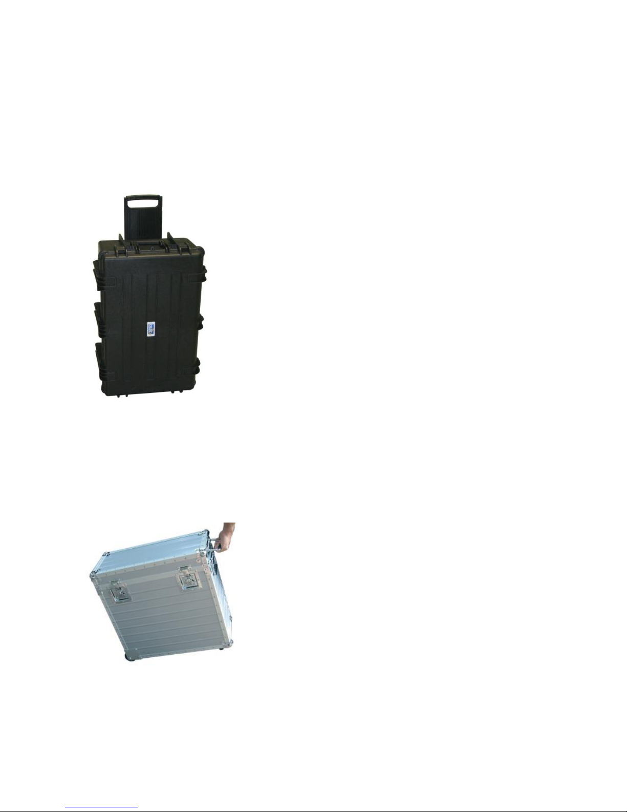
Two types of transit cases are available: molded and aluminum.
3.12.4.1 Molded case; code PII24102
The protection of T3000 from delivery problems is provided by this robust transit case, that
features the following.
- Molded-case construction;
- Handle on the top and on the side;
- Wheels;
- Dimensions: 450 x 550 x 850 mm ;
- Weight : 15 kg.
3.12.4.2 Aluminum case; code PII17102
In alternative to the above, it is possible to use the following aluminum case, that is lighter and
smaller.
- Aluminum metal sheet construction;
- Handles on the side;
- Wheels;
- Dimensions: 400 x 370 x 660 mm ;
- Weight : 11.5 kg.
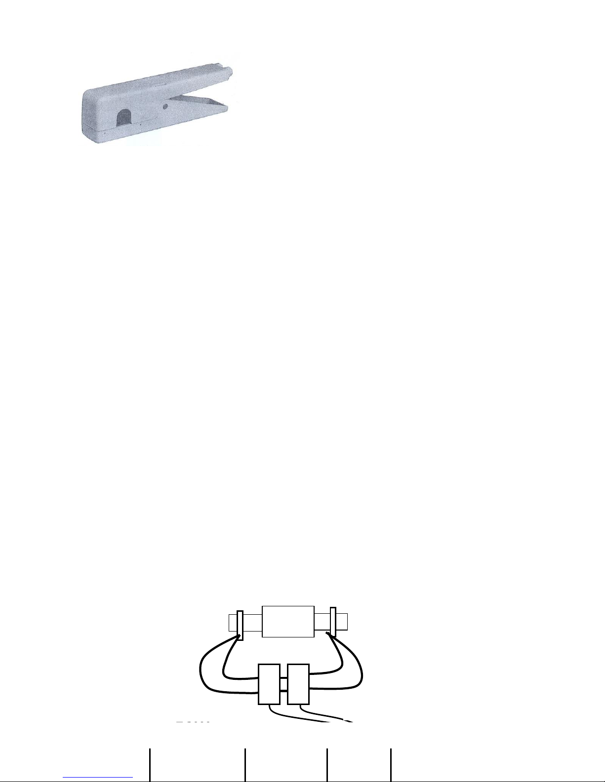
3.12.5 Current clamp code PII16102
The current clamp allows to avoid the opening the secondary current circuit when performing the
primary test of CT burden. The clamp ratio is 1000//1; maximum primary current 100 A; maximum
cable diameter 12 mm.
www.GlobalTestSupply.com
Find Quality Products Online at: [email protected]
Page 25
DOC. SIE10110 Rev. 6 Page 26 of33
3.12.6 Thermal printer PII14102
Thermal printer, for the printout of the V-I curve in the CT saturation test. Paper 112 mm wide.
3.12.7 BU2000: very high AC current boosters
The very high current booster option allows performing high current primary tests with currents up
to 4000 A.
The very high current booster is designed to generate the current while over-loading the generator;
its configuration changes according to the desired current value and duration. The option is made of
two modules:
. Transformers BU2000 MAIN and BU2000 AUX: they include the connection cable to the CT and
the clamps;
. BU2000 INTERPOSING MODULE.
The BU2000 MAIN transformer is used in all versions; the number of BU2000 AUX transformers
can be selected as a function of the desired test current and/or test duration. In case of a single
transformer the interposing module is not necessary.
The option is designed around the concept to avoid wasting power on the connection cables, by
putting the power transformers as close as possible to the test object. This approach is particularly
useful when the test is performed on CT’s in the field, that are from 5 to 10 meters above the
ground. The solution is sound because the weight of transformer plus cable plus clamps is
comparable to the weight of the connection cables. The highest the test current the biggest the
weight of the transformers, but also the biggest the weight of the connection cables. With this
solution, the connection cable to the power source is much lighter, does not pose any major problem
of voltage drop, and can be any length.
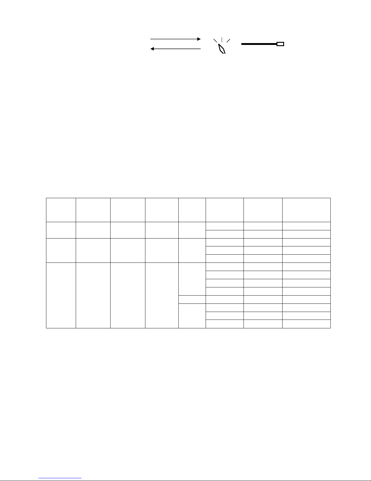
The following sketch shows the connections between T2000, the BU2000 INTERPOSING
MODULE and the transformers (up to 4).
CT UNDER TEST
TRANSFO BOX
T 3000
HIGH I CABLES
CLAMPS
LONG CABLES
www.GlobalTestSupply.com
Find Quality Products Online at: [email protected]
Page 26
DOC. SIE10110 Rev. 6 Page 27 of33
The first transformer, BU2000 MAIN, has two connection cables: one with the supply, the other
one with the output current measurement. The other transformers, BU2000 AUX, have only the
supply cable. All cables are 20 m long.
Connections from T2000 to the BU2000 INTERPOSING MODULE are:
. The variable AC voltage output (not isolated from the mains), that performs the fine current
adjustment;
. The TEST START command, coming from the auxiliary output;
. The TIMER START contact;
. The mains supply.
The following table summarizes the option codes, available configurations and the corresponding
performances.
CODE
N. OF
TRANS.
INTERP.
MODULE
WEIGHT
N. OF
TURNS
TEST
CURRENT
A
SUPPLY
CURRENT
A
ON
DURATION
s
PII50102
1
NO
19.5
3
1000
2.63
INFINITE
2000
20.96
9
PII51102
2
YES
29.5
2
1000
5
INFINITE
2000
20
100
3000
45
6
PII52102
4
YES
49.5
2
1000
5.2
INFINITE
2000
21
1000
3000
47
100
4000
83 9
1
1000
4.5
INFINITE
2000
18
1000
3000
54
50
The table lists:
. The option code;
. The number of transformers of the option;
. The presence of the interposing module;
. The weight to be lifted, that includes: transformers, high current connection cable and connection
clamps;
. The number of turns at the secondary side of the transformers. In the instance of four transformers,
it is possible to have 1 or 2 turns, according to the desired test current and test duration;
. The test current;
. The supply current from the mains;
. The test duration, that is followed by a pause lasting 3 minutes (or a fraction proportional to the
TON/TMAX ratio).
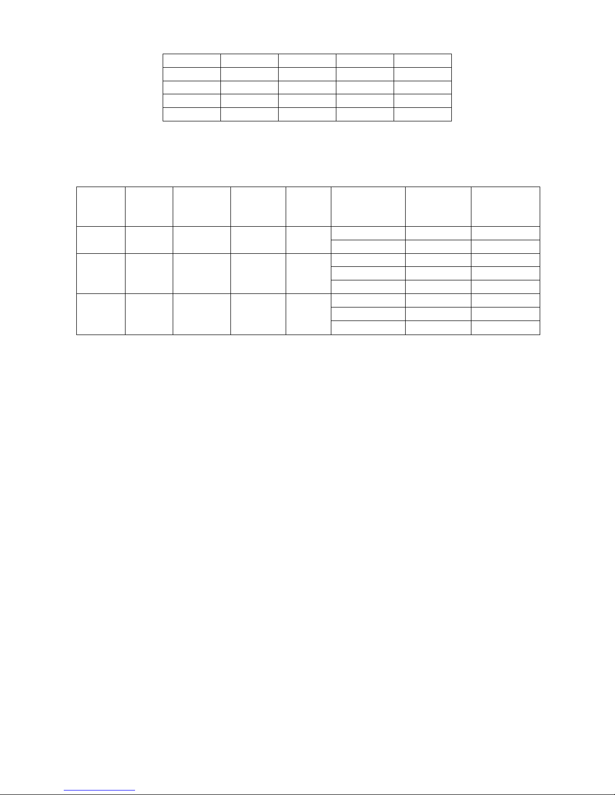
The following table is the same as the above, but it summarizes the test duration as a function of the
test current with the different number of transformers; in brackets the number of turns.
INTERPOSING MODULE
TO THE MAINS
CABLES TO THE
MODULE
www.GlobalTestSupply.com
Find Quality Products Online at: [email protected]
Page 27
DOC. SIE10110 Rev. 6 Page 28 of33
MODEL
1 (3)
2 (2)
4 (1)
4 (2)
1000 A
INF
INF
INF
INF
2000 A
9
100
1000
1000
3000 A
- 6 50
100
4000 A
- - -
9
Above characteristics apply for power supply of 230 V. For the power supply of 115 V, with the
optional T2000 model code PII20110, codes are different, and performances are as follows.
Performance reduction follows the limitation to the supply current.
CODE
N. OF
TRANS.
INTERP.
MODULE
WEIGHT
N. OF
TURNS
TEST
CURRENT
A
SUPPLY
CURRENT
A
ON
DURATION
s
PII57102
1
NO
19.5
3
1000
5.3
INFINITE
2000
42
9
PII58102
2
YES
29.5
2
1000
10.2
INFINITE
2000
40.5
100
2500
63
30
PII59102
4
YES
49.5
1
1000
10,5
INFINITE
2000
41
1000
3000
80
100
Characteristics of the BU2000 INTERPOSING MODULE:
- Mains connection: by a 64 A rated connector, provided.
- Power-on: by means of a circuit breaker rated 63 A.
- Coarse current adjustment: by means of a four-position selector switch.
- Connections to T2000: power supply cord; Variable voltage output; auxiliary contact, timer
START input.
- Capable to drive up to four transformers.
- Weight: 5 kg;
- Dimensions: 33 x 30 x 20 cm (WHD).
NOTE: in case of one transformer, the BU2000 INTERPOSING MODULE is not necessary.
Characteristics of the output transformers: two types.
Type BU2000 MAIN:
- Supply voltage: 230 V (optional 115 V).
- Voltage output (one turn): 0,91 V.
- Steady power: 1000 VA.
- Weight: 11 kg.
- Dimensions: external diameter 190 mm; height 120 mm.
- Connection of the transformer: by a cable, 20 m long, terminated with connectors on both sides.
- Output current metering: by a current transformer with ratio 1000//1. Accuracy class: 0.5%.
- Connection of the CT: by a cable, 20 m long, that includes a shunt, rated 0.1 Ohm, 25 W, accuracy
0.1%. The cable is terminated with a connector for the connection to the 10 V input of T 2000.
Type BU2000 AUX:
- Supply voltage: 230 V (optional 115 V).
- Voltage output (one turn): 0,89 V.
- Steady power: 1000 VA.
- Weight: 10 kg.
- Dimensions: external diameter 190 mm; height 120 mm.
- Connection of the transformer: by a cable, 20 m long, terminated with connectors on both sides.
www.GlobalTestSupply.com
Find Quality Products Online at: [email protected]
Page 28
DOC. SIE10110 Rev. 6 Page 29 of33
Each option is provided with a connection cable having the following characteristics:
- Number of conductors: 2.
- Conductors cross section: 95 sq. mm.
- Conductors type: high flexibility.
- Conductors length: 2.8 m.
- Weight, including the screw-driven clamps: 8.5 kg.
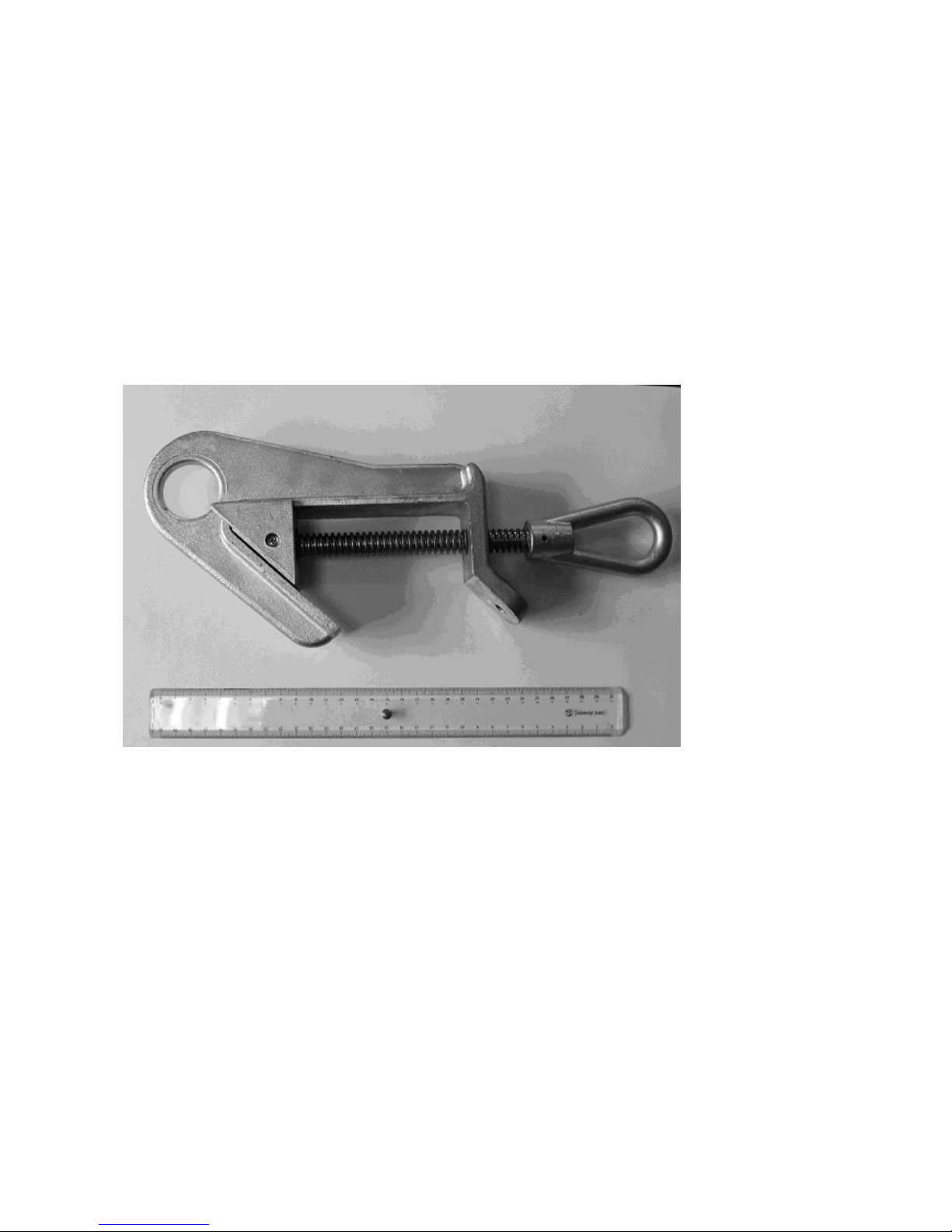
Each option is also provided with two high current screw-driven clamps for the connection to high
bars, having the following characteristics:
- Material: aluminium.
- Opening range: from 5 to 60 mm.
- Short-circuit current rating: 41 kA / 1 s.
- Applicable standard: EN 61230.
- Hole to lift the clamp on the conductor, and ring to screw it up.
The screw-driven clamp is shown in the following picture.
Each option is also provided with four high current clamps for the connection to bars located into
narrow places, having the following characteristics:
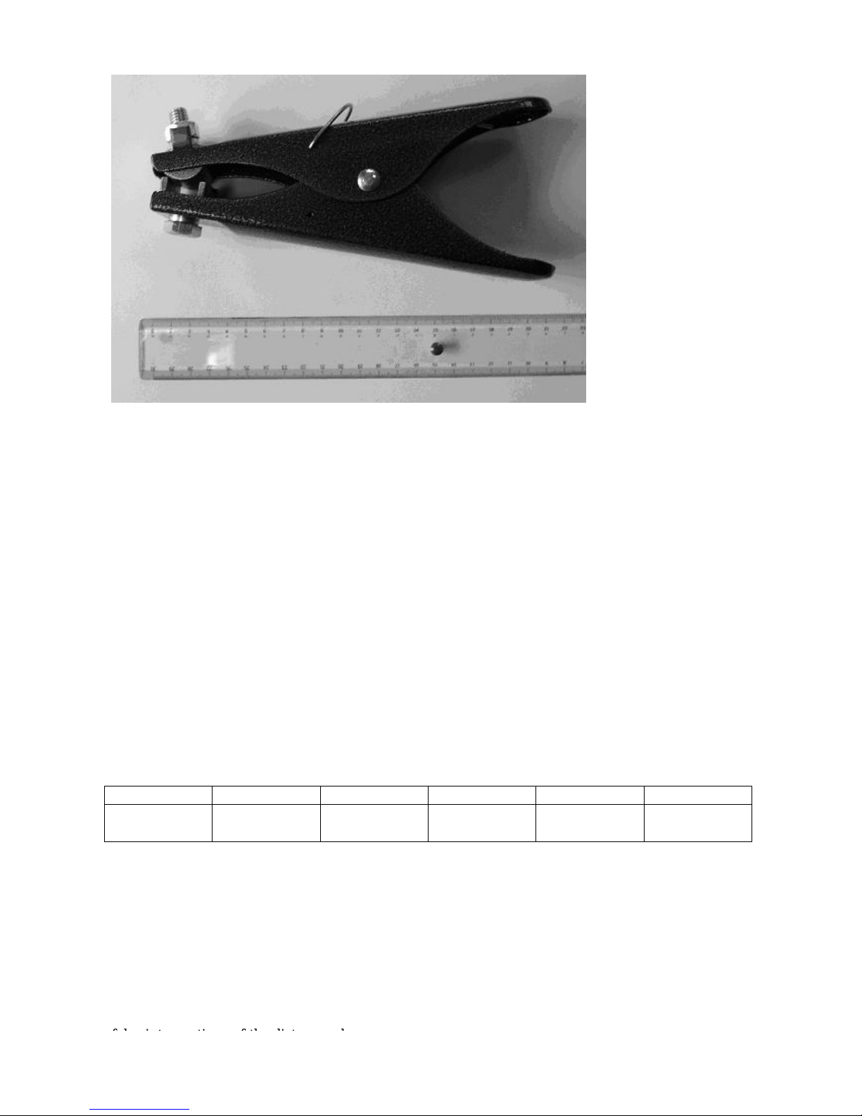
- Material: iron (bronze for the contacts).
- Opening range: up to 60 mm.
- Steady current rating: 800 A / 1 s.
The spring clamp is shown in the following picture.
www.GlobalTestSupply.com
Find Quality Products Online at: [email protected]
Page 29
DOC. SIE10110 Rev. 6 Page 30 of33
Additional options: heavy duty plastic transport case.
The code PII55102 applies to options codes PII50102 and PII57102 (2000 A);
The codes PII55102 and PII56102 apply to options codes PII51102, PII52102, PII58102 and
PII59102 (higher currents).
3.12.8 High I DC module PII13102
The high DC current module allows the measurement of the low contact resistance of high voltage
breakers or of joints. The option is connected to the high AC current output of T2000; the current
measurement is connected to the low DC current measurement input; the drop voltage is connected
to the low voltage measurement input. DC current output is: 100 A steady; 200 A for 4 minutes;
400 A for 15 s.
NOTE: the option can be used only with the 230 V supply.
The selection of this function is performed via menu; the screen displays: test current; joint voltage;
contact resistance. Resistance measurement ranges: 100.0 uOhm, 1.000, 10.00, 100.0 mOhm; 1.000
Ohm, auto-ranging. The option includes two connection cables, with the following characteristics.
Measurement accuracy is summarized in the following table.
RANGE
100.0 uOhm
1.000 mOhm
10.00 mOhm
100.0 mOhm
1000 mOhm
ERROR
± 2% ± 2
uOhm
± 2% ± 10
uOhm
± 2% ± 100
uOhm
± 2% ± 1
mOhm
± 2% ± 10
mOhm
N. 2 High current connection cables, 100 sq. mm, 1 m long, for the connection to T2000.
Terminated on both sides with an high current connectors, M+F.
Dimensions: 285 mm (D) x 325 mm (W) x 295 mm (H) ; weight 20 kg.
3.12.9 SU3000 Safety device for the line impedance measurement, code ZII26102
With T2000 it is possible to measure the zero sequence coefficient of an overhead line, and the
coupling coefficient of parallel lines. Usually this parameter is computed, and an error can cause
false interventions of the distance relay.
www.GlobalTestSupply.com
Find Quality Products Online at: [email protected]
Page 30

DOC. SIE10110 Rev. 6 Page 31 of33
To perform the test, the T2000 output is connected to the overhead line to be tested, that is put out
of service. The purpose of the SU3000 optional device is to protect the operator, during the
connection and during the operation, against possible high voltage spikes.
To this purpose, SU3000 incorporates:
- A voltage suppressor, rated 1000 V AC and 15 kVA;
- An ON/OFF switch, rated 375 A steady, 2000 A peak, 1500 V AC.
- These devices are incorporated in a metal container with door.
-The switch is operated by a safety handle while the door is closed.
- Weight: 20 kg.
- Dimensions: 55 x 45 x 25 cm.
3.12.10 FT/1000 current filter, code PII16093
The filter unit type FT/1000 is an option to be used with the T/X000 relay test sets. It is connected
in series to the relay under test, and guarantees a sinusoidal waveform also when testing current
relays with reverse time characteristics, or with heavily saturating burdens, that tend to distort the
current waveform.
- Current input ranges: 10 - 40 - 100 - 250 A, on terminal bushings.
- Maximum power yield: 800 VA.
- Filter burden: less than 200 VA at 200 A. The burden is proportional to the range (50 VA at 50 A).
- Service: 50 A continuous service; 200 A for 30 s.
- Selection of the mains frequency: 50 or 60 Hz, by switch.
- Overall dimensions: 220 x 250 x 310 mm.
- Weight: 15 kg.
The following is the FT1000 front panel.
3.12.11 Earth resistance and resistivity test kit, code PII19102
The test of earth resistance and resistivity is included in T2000 as a standard feature. The option is
referred to the kit of connection cables and auxiliary spikes that allows executing these tests; it is
optional because not all of our customers perform the tests.
The kit is made of the following devices.
A) Current generation.
- One cable for the connection of T2000 to the auxiliary spike, 100 m long, 2.5 sq. mm cross
section, wound on a wheel. Terminated with a safety banana connector for the connection to the
auxiliary spike, and with a safety socket for the connection to T2000.
- Three cables for the following connections: of T2000 to the above wheel, of the two earth spikes
between them, and of the measurement input to the measurement wheel; 4 m long, 2.5 sq. mm
cross section. Terminated on both sides with a safety banana connector.
www.GlobalTestSupply.com
Find Quality Products Online at: [email protected]
Page 31

DOC. SIE10110 Rev. 6 Page 32 of33
- Two cables for the connections of T2000 to the local earth system, both for generation and
measurement, 10 m long, 2.5 sq. mm cross section. Terminated on both sides with a safety banana
connector.
- Two auxiliary earth spikes, screw shaped, for the dispersion of the current into the soil. Length:
0.95 m; screwed section 0.6 m. Material: zinc-plated iron. Complete with socket for the connection
to the generator.
- Handle to screw the spike into the ground.
- One current clamp to connect T2000 to the local earth system.
B) Voltage measurement
- One cable for the connection of T2000 to one voltage spike, 50 m long, 2,5 sq. mm cross section,
wound on a wheel. Terminated with a safety banana connector for the connection to the voltage
spike, and with a safety socket for the connection to T2000.
- Two auxiliary earth spikes, to measure the voltage drop; material: zinc-plated iron; length: 0.5 m.
Complete with connector for the measurement cable.
- One measurement clamp to connect T2000 to the local earth system.
www.GlobalTestSupply.com
Find Quality Products Online at: [email protected]
Page 32

DOC. SIE10110 Rev. 6 Page 33 of33
4 PROTECTIONS
- If the test set is not connected to the ground, the test set does not allow for power generation, and
warns the operator with a diagnostic message.
- Fuse on the mains supply.
- At power-on, a diagnostic sequence controls:
. Key microprocessor board components;
. Auxiliary supply voltages.
If something is wrong, the operator is alerted by a message.
- Emergency pushbutton: if pressed, all main outputs are removed.
- The high voltage output has the following protections:
. Confirmation key: if not turned, the HV output is not generated;
. The HV is generated only if selected; the HV selection is confirmed by warning lights;
. It is impossible to start generating the HV unless the adjustment knob is at zero.
- Thermal (NTC) sensor on the main and auxiliary transformers. In case of over-temperature, an
alarm message is displayed.
- Thermal sensor on the electronic switch (SCR) that controls current injection, and of the internal
temperature. In case of over-temperature, an alarm message is displayed.
- If maximum current limits and time duration of power transformer generators are trespassed, the
generation is interrupted, and the operator is warned by an alarm message. Note that the opening
action is driven directly, and it is not influenced by any possible problem on the microprocessor.
- The 20 mA measurement input is protected by a fuse against wrong connections. The fuse is a
PTC resistor, that increases its value and self-restores in some minutes.
www.GlobalTestSupply.com
Find Quality Products Online at: [email protected]
 Loading...