

Page 1

S
PECIFICATIONS
DOCUMENT No. SIE10175, Rev. 14, «Date»
STS + TD 5000 FAMILY
for the test of CT, VT and PT
Shop for Power Metering products online at:
1.877.766.5412
www.PowerMeterStore.c a
Page 2

T
ABLE OF CONTENTS
SPECIFICATIONS .......................................................................................................................................................... 1
1 GENERAL .............................................................................................................................................................. 7
2 APPLICABLE STANDARDS ....................................................................................................................................17
3 CHARACTERISTICS ...............................................................................................................................................19
3.1 F
OREWORD
............................................................................................................................................................ 19
3.2 M
AIN GENERATOR
................................................................................................................................................... 19
3.2.1 High AC current ........................................................................................................................................... 20
3.2.2 High DC current ........................................................................................................................................... 20
3.2.3 Low AC current ............................................................................................................................................ 21
3.2.4 Low DC current ............................................................................................................................................ 21
3.2.5 High AC voltage ........................................................................................................................................... 22
3.2.6 Low AC voltage ............................................................................................................................................ 23
3.2.7 High power output to the external modules ............................................................................................... 24
3.2.8 Output frequency ........................................................................................................................................ 24
3.2.9 Other features of main outputs ................................................................................................................... 24
3.3 O
UTPUTS MEASUREMENT
......................................................................................................................................... 25
3.4 E
XTERNAL INPUTS MEASUREMENT
.............................................................................................................................. 25
3.5 T
IMER
................................................................................................................................................................... 26
3.6 P
HASE ANGLE
......................................................................................................................................................... 26
3.7 O
THER MEASUREMENTS
........................................................................................................................................... 27
3.8 D
ISPLAY
................................................................................................................................................................. 29
3.9 T
EST CONTROL
........................................................................................................................................................ 29
3.10 M
ENU SELECTIONS
............................................................................................................................................... 30
3.11 S
TANDARD CONNECTION CABLES (LONG CABLES CODE
PII16175
AND EXTRA LONG CABLES CODE
PII57175) ........................ 47
3.12 O
THER CHARACTERISTICS
....................................................................................................................................... 48
4 OPTIONS .............................................................................................................................................................49
4.1 T
RANSIT CASES (CODE
PII17175, PII 19175, PII51175) .............................................................................................. 49
4.2 PADS
LICENCE (CODE
PII10176P, PII10176F, PII10176T) ......................................................................................... 50
4.3 R
EMOTE SAFETY SWITCH (CODE
PII42175) ................................................................................................................. 51
4.4 W
ARNING STROBE LIGHT (CODE
PII43175) ................................................................................................................. 51
4.5 STCS
AUTOMATIC CONNECTION WINDINGS MODULE (CODE
PII12175) ............................................................................. 52
4.6 STCS
POWER GENERATOR BOOSTER 20 A DC (CODE
PII32175) ..................................................................................... 53
4.7 STDE
RESIDUAL MAGNETIZATION REMOVAL MODULE (CODE
PII27175) ............................................................................ 54
4.8 STSA S
URGE ARRESTER (CODE
PII46175)................................................................................................................... 55
4.9 BUX 3000, BUX 2000
CURRENT BOOSTER (CODES
PII50175, PII56175)....................................................................... 55
4.10 C
URRENT CLAMP (CODE
PII16102) ........................................................................................................................ 57
4.11 PLCK P
OLARITY CHECKER (CODE
PII41175) ............................................................................................................ 58
4.12 STLG
CURRENT INJECTION POWER TRANSFORMER FOR GROUND TESTS (CODE
PII70175) .................................................. 58
4.13 P
OWER FACTOR CORRECTION MODULE (CODE
PII85175) ........................................................................................... 59
4.14 STLG
LARGE STATION (CODE
PII88175) .................................................................................................................. 60
4.15 STSG
SAFETY GROUNDING MODULE (CODE
PII71175) ............................................................................................... 62
4.15.1 Cylindrical studs ....................................................................................................................................... 63
4.15.2 Surge arrester for STSG (code PII77175) .................................................................................................. 63
4.16 G
ROUND GRID TEST ACCESSORIES KIT (CODE
PII76175) ............................................................................................ 64
4.17 C
URRENT CLAMP METER (CODE
PII79175) ............................................................................................................. 65
4.18 F
OLDABLE TROLLEY (CODE
PII18175) ..................................................................................................................... 66
4.19 TD 5000
MODULE FOR THE TAN(Δ) LOSS ANGLE FACTOR MEASURE (CODE
PII11175) ...................................................... 66
4.20 CAP-CAL
REFERENCE CAPACITOR (CODE
PII40175) .................................................................................................. 72
4.21 STOIL
CELL FOR THE INSULATING OIL CHECK (CODE
PII13175) ..................................................................................... 73
Shop for Power Metering products online at:
1.877.766.5412
www.PowerMeterStore.c a
Page 3

4.22 D
IGITAL THERMO HYGROMETER (CODE
PII44175) .................................................................................................... 73
4.23 RCTD
REACTOR FOR MOTORS AND GENERATORS MEASURES (CODE
PII47175) ............................................................... 74
5 PROTECTIONS .....................................................................................................................................................76
Shop for Power Metering products online at:
1.877.766.5412
www.PowerMeterStore.c a
Page 4

Disclaimer
Every effort has been made to make this material complete, accurate, and up-to-date. In addition, changes are
periodically added to the information herein; these changes will be incorporated into new editions of the publication.
ISA reserves the right to make improvements and/or changes in the product(s) and/or the program(s), described in this
document without notice, and shall not be responsible for any damages, including but not limited to consequential
damages, caused by reliance on the material presented, including but not limited to typographical errors.
Copies, reprints or other reproductions of the content or of parts of this publication shall only be permitted with ISA
prior written consent.
All trademarks are the property of their respective holders.
Copyright 2015© ISA S.r.l. Italy - All rights reserve
Shop for Power Metering products online at:
1.877.766.5412
www.PowerMeterStore.c a
Page 5
1 G
ENERAL
The portable, high accuracy test sets of the STS family allow performing all tests foreseen by international Standards on
CTs, measurement VTs, Power Transformers, and to measure the Tan(δ), dissipation factor and capacitance of any
device. With the option STLG + STSG it is also possible to execute the Earth resistance and Step and Touch voltage
measurements.
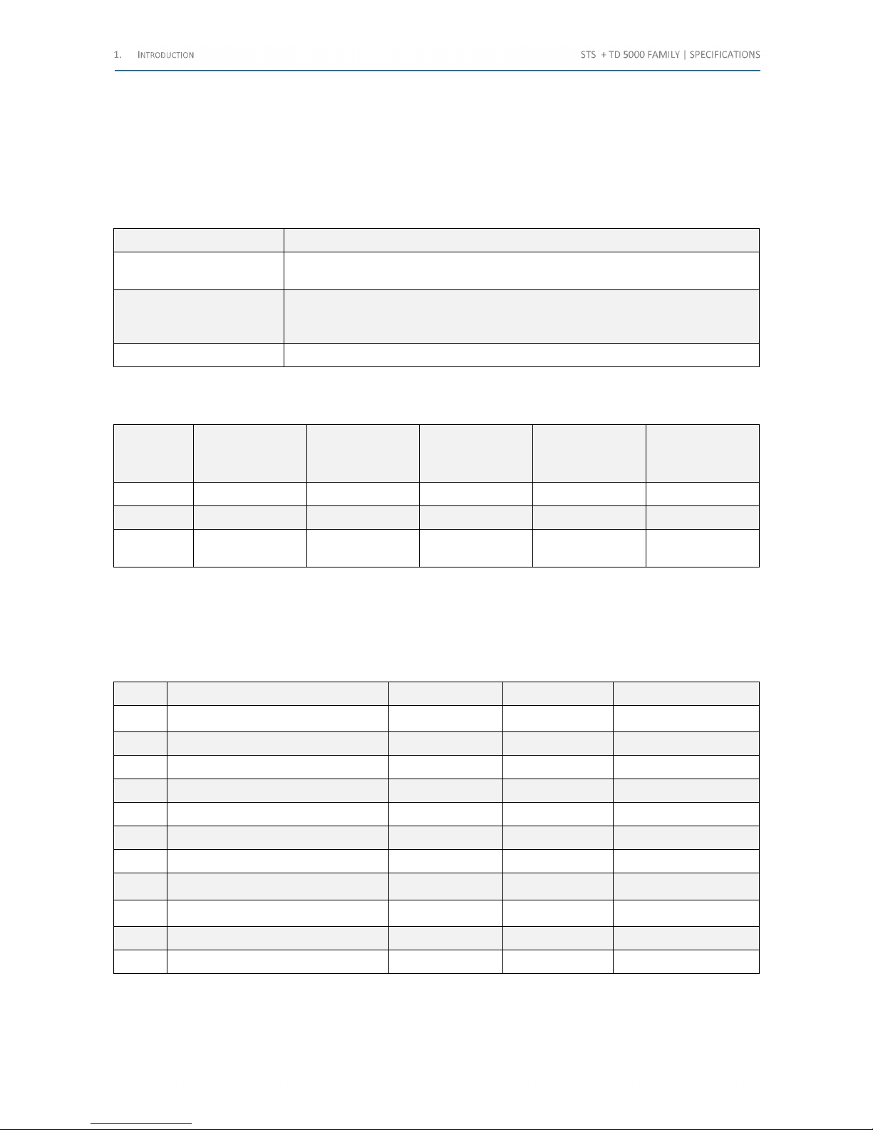
The following table lists the models of the STS Family:
Model Description
STS 5000
It is the most performing test set of the STS family of devices. It allows executing all
listed tests
STS 4000
It is the same as STS 5000, unless the high AC and DC current generators. High AC
current tests can be performed using the BUX 3000 option; micro-Ohm metering is
not available
STS 3000 light It allows performing Tan(δ) tests with the option TD 5000
Table 1 - STS Family models
The following table summarizes the differences among the models:
Model
High current, AC
& DC
High voltage
Low Ac-DC
outputs
Optional Tan(δ)
tests
TD 5000
Optional High AC
current
BUX 3000
STS 5000 X X X X X
STS 4000 X X X X
STS 3000
light
X
Table 2 - Differences among the STS Family models
Keyboard, dedicated keys, control knob and display can control all test sets of the family locally. Test results and settings
can be saved in a PC by the software suite TDMS, which comes with the device. The optional PADS program allows also
controlling the device from the PC.
The following table lists the tests performable by the Current Transformers:
No. Test STS 5000 STS 4000 STS 3000 light
1 Ratio Polarity and Burden X
+BUX
+Manual Measure
+BUX
+Manual Measure
2 Burden Secondary Side X X
3 Excitation Curve X X
4 Winding or Burden Resistance X X
5 Voltage Withstand X X
6 Polarity Check X
7 Ratio Polarity Voltage Mode X X
8 Rogowski (Ratio) X
+BUX
+Manual Measure
+BUX
+Manual Measure
9 Low Power (Ratio) X
+BUX
+Manual Measure
+BUX
+Manual Measure
10 Tangent δ TD 5000 TD 5000 TD 5000
11 Ratio IEC61850-9-2LE X
Table 3 - Current Transformer tests
BUX is the BUX 3000, BUX 2000 option, for high current injection tests. The Ratio test for Not-Conventional transformer
with the option IEC61850-9-2LE is available only in remote control mode, using the PADS software.
Shop for Power Metering products online at:
1.877.766.5412
www.PowerMeterStore.c a
Page 6
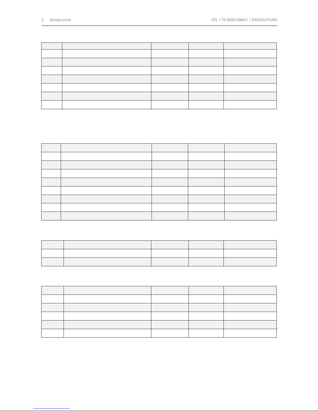
The following table lists the tests performable by the Voltage Transformers:
No. Test STS 5000 STS 4000 STS 3000 light
1 Ratio X X
2 Ratio Electronics X X
3 Burden X X
4 Voltage Withstand X X
5 Polarity Check X
6 Tangent δ TD 5000 TD 5000 TD 5000
7 Ratio IEC61850-9-2LE X X
Table 4 - Voltage Transformers tests
The Ratio test for Not-Conventional transformer with the option IEC61850-9-2LE is available only in remote control
mode, using the PADS software.
The following table lists the tests performable by the Power Transformers:
No. Test STS 5000 STS 4000 STS 3000 light
1 Ratio X X
2 Winding Resistance X X
3 Winding Resistance – Auto X X
4 Voltage Withstand X X
5 Short-Circuit Impedance X X
6 No-Load Current X X
7 Tangent δ TD 5000 TD 5000 TD 5000
8 Demagnetizer X X
Table 5 – Power Transformers tests
The following table lists the tests performable by the Circuit Breakers:
No. Test STS 5000 STS 4000 STS 3000 light
1 Resistance - μΩ X
2 Tangent δ TD 5000 TD 5000 TD 5000
Table 6 - Circuit Breakers tests
The following table lists the tests performable by the Resistances:
No. Test STS 5000 STS 4000 STS 3000 light
1 Resistance - μΩ X
2 Earth Resistance X X
3 Soil Resistivity X X
4 Step and Touch X X
5 Line Impedance X X
Table 7 – Resistances tests
Shop for Power Metering products online at:
1.877.766.5412
www.PowerMeterStore.c a
Page 7

The test Ratio IEC61850-9-2LE can be executed only in remote mode, using the PADS software.
Tests are performed in accordance with the following standards:
• IEC EN 60044-1
• IEC EN 60044-2
• IEC EN 60044-5
• IEC EN 60044-7
• IEC EN 60044-8
• IEC EN 61869-x
• IEC EN 60076-1
• ANSI/IEEE C57.13.1
Earth resistance and step and touch tests are performed according to the following standards:
• IEC EN 20522:2011
• IEEE 80:2000
• IEEE 81:1983
• DIN VDE 0101
• CENELEC HD 63761
STS Family has the facility to test not conventional CT, VT, Merging Unit (MU), by the IEC 61850-9-2 (SV) protocol.
STS Family generates current or voltage and injects these quantities into primary side of the CT or VT under test.
STS Family then reads the data from the network using its Ethernet port (Sample Values) in order to perform a variety
of different tests, as CT ratio and polarity up to 800 A or up to 2000 A (with BUX 2000) or 3000 A (with BUX 3000). It is
also possible to check the VT ratio and polarity, up to 2 kV. Test of MU.
Shop for Power Metering products online at:
1.877.766.5412
www.PowerMeterStore.c a
Page 8
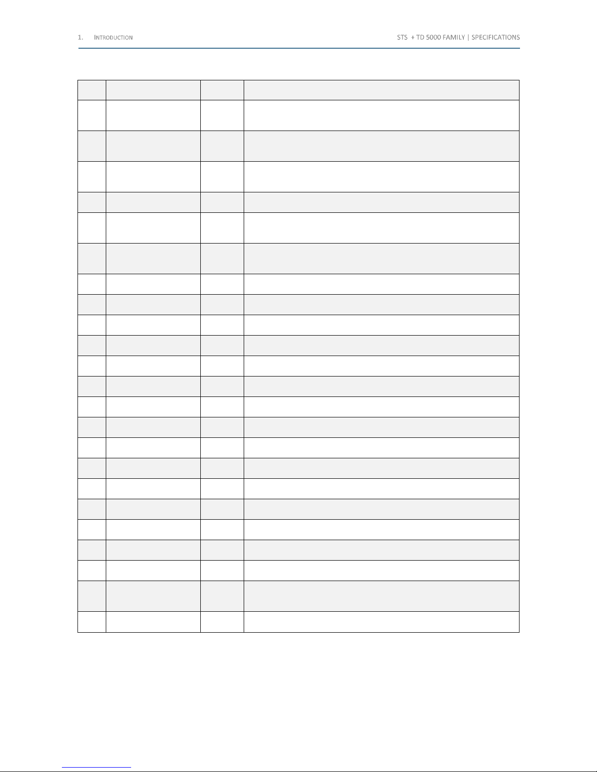
The following table lists the optional modules enhance the STS features:
Item Option Code Description
1 Transit Cases
PII17175
PII19175
PII51175
They allow transporting the device
2 PADS license
PII10176P
PII10176T
PII10176F
PC Remote control of the test set
3 Remote Safety Switch PII42175
When the Remote Safety Switch is connected and enabled, it avoids any
current or voltage generation from pressing START/STOP button on the STS
only
4 Warning Strobe Light PII43175 It alerts when the test is performed
5 STCS PII12175
The Circuit Switch option performs the automatic measurement of the
following parameters: PT transformer ratio, PT winding resistance, OLTC
dynamic winding resistance
6 STCS Booster 20 A DC PII32175
The Circuit Switch option performs the automatic measurement of the
following parameters: PT winding resistance up to 20 A DC, OLTC dynamic
winding resistance up to 20 A DC
7 STDE PII27175
It allows neutralizing the residual magnetization of the power transformer core
after the winding resistance test
8 STSA PII46175 The option limits voltage surges generated on the 10 V input
9
BUX 3000
BUX 2000
PII50175
PII56175
This option performs high current tests, with currents up to 3,000 A or 2,000 A
10 Current Clamp PII16102
The current clamp avoids opening the secondary current circuit when
performing the primary test of CT burden
11 PLCK PII41175 Sawtooth signal detector for CT/VT polarity test
12 STLG PII70175
It is a high power transformer for the current injection for the Line Impedance
and Step and Touch tests
13
Power factor correction
module
PII85175
It is a module to increase the current in the grounding and step and touch
tests
14 STLG large stations PII88175
It is a high power transformer for current injection into transmission lines for
large stations
15 STSG PII71175 This option is used for the test of overhead lines parameters
16
Ground Grid test
accessories kit
PII76175
The kit includes some accessories to perform the Soil Resistivity test, the Earth
Resistance test and the Step and Touch test
17 Current Clamp Meter PII79175 This option is used to check the induced current in the transmission line
18 Foldable Trolley PII17175 The trolley eases the transport of STS + TD 5000
19 TD 5000 PII11175
It performs the measurement of the Tan(δ), capacitance and Power factor of
any device, at the frequency of the mains or in a wide frequency range
20
CAP-CAL
(for TD 5000)
PII40175
Purpose of the reference capacitor is to check the actual calibration of TD for
the measures of the capacitance and Tan(δ)
21
STOIL
(for TD 5000)
PII13175 The oil cell is for Tan(δ) measurement of PT oil
22
Digital thermo
hygrometer
(for TD 5000)
PII44175
The option allows measuring ambient temperature and humidity, and to input
them into the test settings, if it is necessary
23
RCTD
(for TD 5000)
PII47175 Compensation Inductor for high current Tan(δ) test on motors and generators
Table 8 - Optional modules
Shop for Power Metering products online at:
1.877.766.5412
www.PowerMeterStore.c a
Page 9

The basic STS function is to generate current and voltages, as requested by the type of test to be performed; only one
test at a time. The test is selected on the LCD screen by means of the multi-function knob. Test results are kept in local
memory or in a USB card, and can be transferred to a PC later, along with settings.
The capacitance and Tan(δ) measurements with TD 5000 can be performed on CTs, VTs, CBs, PTs and bushings.
STS 5000 contains a generator, with the following six outputs:
• High AC current
• Low AC current
• High DC current
• Low DC current
• High AC voltage
• Low AC voltage
In addition, there is a high power AC voltage output, not isolated from the mains, which supplies the external options
(TD 5000, BUX 2000, BUX 3000, STLG, STCS Booster 20 A DC).
In local control mode, the selected output is adjustable and metered on the large, graphic LCD display. With the control
knob and the LCD display it is possible to enter the MENU mode, which allows setting many functions: this makes STS a
very powerful testing device, with manual and automatic testing capabilities, and with the possibility to transfer test
results to a PC via USB, ETHERNET or Pen Drive.
In the PC control mode, the PADS program allows performing the same tests as in the local mode, with the same control
windows. It allows also downloading, displaying and analyzing test results obtained in local mode.
PADS operates with all WINDOWS versions.
The ease of operation has been the first goal of STS: this is why the LCD is graphic, and so large. With it, the dialogue in
menu mode is made easy. Besides, all STS outputs relevant to the selected test are continuously measured, and output
values are displayed, with no extra effort to the operator.
STS feature four measurement inputs:
• DC voltage, up to 10 V DC
• AC or DC voltage
• High range, up to 300 V
• Low range, up to 3 V
• AC or DC current, up to 10 A
All inputs, unless the 3 V and 300 V voltage measurements, are isolated among them, and allow measuring CT or VT
outputs or any other source.
In all STS models, it is available a digital input, which accepts an input, which can be voltage free, or with a voltage up
to 300 V. It allows measuring the time response of a protection relay. It is also possible to test the M.V. CB’s timing: the
time is stopped when the injected current is opened by the CB.
The instrument is housed in a transportable aluminum box, which is provided with removable cover and handles for
ease of transportation. An optional trolley is also available.
Shop for Power Metering products online at:
1.877.766.5412
www.PowerMeterStore.c a
Page 10
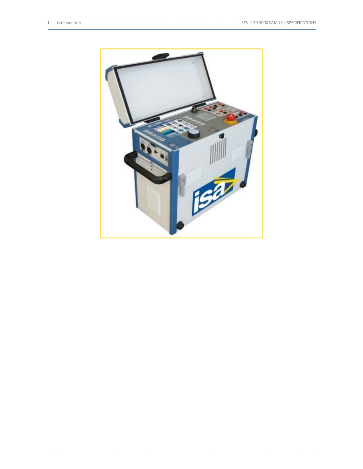
The following image exhibits the STS 5000 as an example of the model of the family, with the protection cover lifted:
Figure 1 - STS 5000
Shop for Power Metering products online at:
1.877.766.5412
www.PowerMeterStore.c a
Page 11
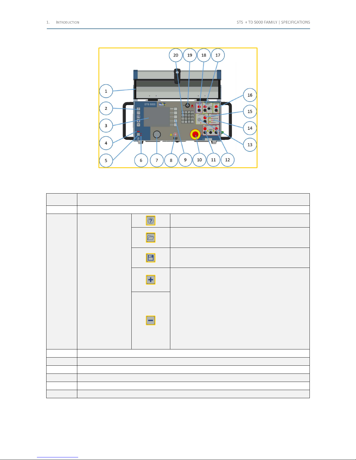
The following image exhibits the front panel:
Figure 2 - Test set front panel
The following table lists all the elements of the front panel:
ITEM Component
1 Cover
2 Pushbuttons
Help. Pressing it, the screen displays the information
related to the test performed
Open file. It allows to access the list of saved test results
(the list can be located in the internal memory or on the
USB key)
Save file. It allows saving the test result. Pressing it, it is
possible to access the list of saved test results (the list can
be located in the internal memory or on the USB key)
Increment and decrement buttons. To input a value, select
the field, and then:
• Edit the desired value, via the keypad
• Increment or decrement the value, pressing the above
pushbuttons
• Rotate the knob clockwise (increment) or anti-
clockwise (decrement)
• Press the keyboard up key to increment, and the
keyboard down key to decrement
The amount of the increment or decrement is: ten units, for
the plus and minus keys; one unit, for the knob, and one
tenth, for the up-down arrows
3 Display
4 Power-on light: it is ON when the test set is operating
5 Power ON and OFF push-button
6 Mains lights: they turn on very shortly as the test set is connected to the mains
7 MENU control knob, with switch
8 Test START and STOP push-button
Table 9 - Frontal panel components (1/2)
Shop for Power Metering products online at:
1.877.766.5412
www.PowerMeterStore.c a
Page 12
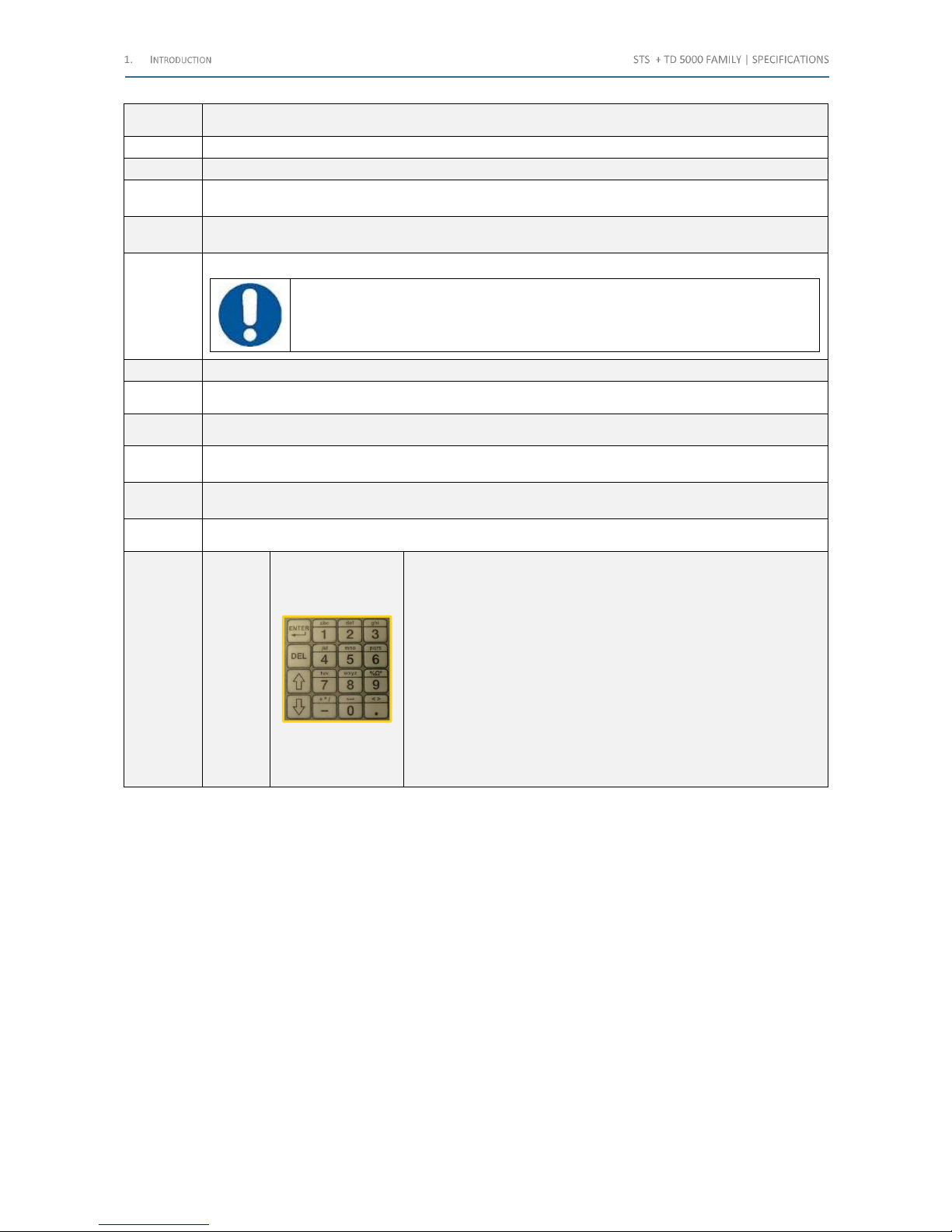
ITEM Component
9 16-keys alpha-numeric keyboard
10 Emergency push-button with lock-in
11
AC voltage and current output, up to 6 A – 70 V or 3 A - 140 V, fuse protected. Fuse rating: FF 6.3 A
250 V. The LED turns ON when it is active
12
DC current output, up to 6 A, fuse protected. Fuse rating: T 6.3 A 250 V. The LED turns ON when it is
active
13
AC voltage input connector, up to 3 V. The LED turns ON when it is active
ATTENTION: The connector to this input can be removed only acting on the connector
body. Do not pull the cable
14 Active output lights. The LED turns ON when the corresponding output is active
15 AC or DC voltage input sockets, up to 300 V. The LED turns ON when it is active
16 DC voltage input sockets, up to 10 V. The LED turns ON when it is active
17
AC or DC current input sockets, up to 10 A, fuse protected. Fuse rating: FF 10 A 250 V. The LED turns
ON when it is active
18
Digital input sockets, for voltage clean contact or with voltage up to 300 V. The LED turns ON when the
input is closed or with voltage
19 Enable key, for HV tests
20
Function
keys
• The twelve buttons to the right behave as a portable phone
• ENTER confirms what is edited
• DEL
o If the field is numeric, it deletes the first digit to the left. It is
not possible to select the digit to delete: as the wheel is
touched, the digit changes
o If the field is alphabetic, it is possible to use the knob to
reach for the letter to be deleted: the deleted letter is the
one to the left with respect to the cursor. If the cursor is
completely to the left, DEL deletes the letter to the right
• As explained above the arrows, when the context is numeric,
increment or decrement the value; in a selection page, they
allow to move around
Table 10 – Frontal panel components (2/2)
Shop for Power Metering products online at:
1.877.766.5412
www.PowerMeterStore.c a
Page 13
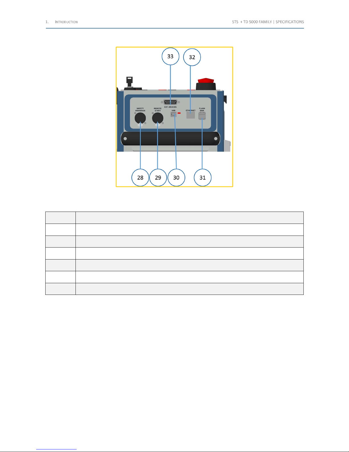
The following iamge exhibits the side panel on the left:
Figure 3 – Left panel components
The following table lists the elements of the left panel:
ITEM Component
28
Alarm output connector, for the light strobe with buzzer option PII43175
29
Remote start input connector, for the remote push-button option PII42175
30
USB connection only for ISA diagnostic
31
Flash disk connector for the local test results saving or for moving the local test results from the local memory
32
ETHERNET connection to the PC. It incorporates two lights which turn on when the test set is connected
33
Communication Connector to the external devices (TD 5000, STCS, STDE)
Table 11 – Left panel components
Shop for Power Metering products online at:
1.877.766.5412
www.PowerMeterStore.c a
Page 14
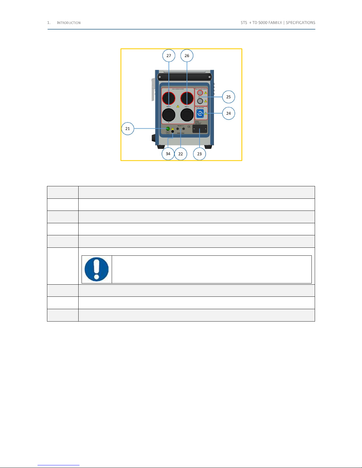
The following image exhibits the side panel on the right:
Figure 4 - Right panel components
The following table lists the elements of the right panel:
ITEM Component
21 Ground connection socket
22 Resettable power supply automatic fuses, rated 16 A 240 V
23 Power supply plug
24 Power supply connection to external optional modules (TD5000, BUX3000, STCS Booster 20 A DC)
25
High voltage output connectors, rated 2 kV AC
ATTENTION: The connectors to this input can be removed only acting on the
connector body. Do not pull the cable
26 High AC current output connectors, rated 800 A
27 High DC current output connectors, rated 400 A
34 F6 fuse
Table 12 – Right panel components
Shop for Power Metering products online at:
1.877.766.5412
www.PowerMeterStore.c a
Page 15
2 A
PPLICABLE STANDARDS
The test set conforms to the EEC directives regarding Electromagnetic Compatibility and Low Voltage instruments.
The following table lists the standards related to the EMC Directive, 2004/108/EC:
Standard Title Requirement
EN 61326
Electrical equipment for measurement, control
and laboratory use. EMC requirements. General
requirements
IEC EN 61000-3-2:
Electromagnetic compatibility (EMC)
- Part 3-2:
Limits - Limits for harmonic current emissions
(equipment input current ≤ 16 A per phase)
Harmonic content of power supply
Acceptable limits: basic
IEC 61000-3-2
Electromagnetic compatibility
(EMC)
- Part 3-3:
Limits - Limitation of voltage changes, voltage
fluctuations and flicker in public low-voltage
supply systems, for equipment with rated current
≤16 A per phase and not subject to conditional
connection
Limitation of voltage fluctuations and flicker
Acceptable limits: basic
CISPR 16-1
Specification for radio disturbance and immunity
measurement apparatus and methods
Acceptable limits for conducted emission:
• 0.15÷0.5 MHz: 79 dB pk; 66 dB avg
• 0.5÷5 MHz: 73 dB pk; 60 dB avg
• 5÷30 MHz: 73 dB pk; 60 dB avg
Acceptable limits for radiated emission:
• 30÷230 MHz: 40 dB (30 m)
• 230÷1000 MHz: 47 dB (30 m)
IEC EN 61000-4-2
Electromagnetic compatibility (EMC)
- Part 4-2:
Testing and measurement techniques Electrostatic discharge immunity test
Immunity tests for ESD
Test values: 8 kV in air; 4 kV in contact
IEC EN 61000-4-3
Electromagnetic compatibility (EMC)
- Part 4-3:
Testing and measurement techniques - Radiated,
radio-frequency, electromagnetic field immunity
test
Immunity tests for radio frequency interference
Test values (f= 900 ± 5 MHz): field 10 V/m,
modulated AM 80%; 1 kHz
IEC EN 61000-4-4
Electromagnetic compatibility (EMC)
- Part 4-4:
Testing and measurement techniques - Electrical
fast transient/burst immunity test
Immunity tests for high speed transients (burst)
Test values: 2 kV peak; 5/50 ns
IEC EN 61000-4-5:
Electromagnetic compatibility (EMC)
- Part 4-3:
Testing and measurement techniques - Radiated,
radio-frequency, electromagnetic field immunity
test
Immunity tests for surge
Test values: 1 kV peak differential mode; 2 kV peak
common mode; 1.2/50 us
IEC EN 61000-4-6:
Electromagnetic compatibility (EMC)
- Part 4-6:
Testing and measurement techniques - Immunity
to conducted disturbances, induced by radiofrequency fields
Immunity to low-voltage sinusoidal waveform
Test values: 0.15-80 MHz, 10 Vrms, 80% AM 1 kHz
IEC EN 61000-4-8:
Electromagnetic compatibility (EMC)
- Part 4-8:
Testing and measurement techniques - Power
frequency magnetic field immunity test
Immunity tests for low frequency magnetic fields.
Test values: 30 Arms/m
IEC EN 61000-4-11
Electromagnetic compatibility (EMC)
- Part 4-11:
Testing and measurement techniques - Voltage
dips, short interruptions and voltage variations
immunity tests
Immunity test for power supply drops. Test value: 1
cycle; 100% drop
Table 13 – Standards related to the EMC Directive (2/2)
Shop for Power Metering products online at:
1.877.766.5412
www.PowerMeterStore.c a
Page 16
The following table lists the standards related to the LV Directive, 2006/95/EC:
Standard Title Requirement
IEC EN 61010-1
Safety requirements for electrical
equipment for measurement, control, and
laboratory use - Part 1: General
requirements
For a pollution degree 2: dielectric rigidity 1.4 kV AC, 1
minute
The rigidity is 4600 V AC 1 minute between the high voltage
output and the rest of inputs and outputs.
• Inputs/outputs protection: IP 2X, per IEC 60529, for all
but high voltage outputs; IP4X for high voltage
outputs
• Insulation resistance, at 500 V DC: > 10 MΩ
• Ground resistance, at 200 mA DC: < 0.1 Ω
• Operating temperature: (-10÷55) °C;
storage: (-20÷70) °C
• Operating relative humidity: 5÷95%, without
condensing. Storage relative humidity: 0÷96%,
without condensing
• Altitude: less than 2,000 m
IEC 60068-2-6
Environmental testing - Part 2-6: Tests - Test
Fc: Vibration (sinusoidal)
Vibration: 20 m/s2 at 10÷150 Hz
IEC 60068-2-27
Environmental testing - Part 2-27: Tests Test Ea and guidance: Shock
Shock: 15 g; 11 ms; half-sine
Table 14 - Standards related to the LV Directive
Shop for Power Metering products online at:
1.877.766.5412
www.PowerMeterStore.c a
Page 17

3 C
HARACTERISTICS
3.1 Foreword
STS incorporates a generator with six outputs. When an output is generated, there is voltage also on all other outputs,
unless for the high AC voltage.
The generator is made of an electronic type D switching amplifier, followed by a power transformer, which adapts the
suitable current or voltage output.
3.2 Main generator
The main generator has six outputs:
• High AC current
• High DC current
• Low AC current
• Low DC current
• High AC voltage
• Low AC voltage
Output adjustment is performed automatically, as a function of the selected test. The following specification applies to
the separate use of these outputs.
For all outputs, the following applies:
• Type of generator. Electronic type D switching amplifier, followed by a high power transformer, with a number
of secondary windings, fort the following outputs: high AC current, high DC current, high AC voltage. Loop
control of the selected output. The transformer includes also the outputs: Low AC current, Low DC current,
Low AC voltage, but they are not loop controlled
• Output adjustable from zero to the maximum value
• The specified output power is available at 25 °C maximum of external temperature, and with a power supply
error of 2% maximum. For higher temperatures, the maximum power decreases of 20 VA/°C
• The specified output accuracy and THD applies at (25±2) °C, resistive load, and burden less than 20% of the
maximum, currents up to 50% of the maximum. With full temperature range, maximum current and maximum
burden, errors are twice as bigger
• The specified output characteristics may vary for frequencies below 50 Hz and above 60 Hz
• The generated frequency can be synchronized with the mains (with the Power Line Synchronizer option)
• The selected output is shown by a LED
Shop for Power Metering products online at:
1.877.766.5412
www.PowerMeterStore.c a
Page 18
3.2.1 High AC current
The output is available only on the STS 5000.
The following table lists the output characteristics, at 50 to 60 Hz and supply of 230 V:
Current output
[A]
Output power
[VA]
Load time
[s]
800 4,800 25
600 3,780 200
400 2,560 500
300 1,940 900 (15 min)
200 1,300 > 2 h
Table 15 - High AC current: output characteristics (1/2)
ATTENTION: The output range decreases below 50 Hz and above 60 Hz
The following table lists some more characteristics:
Connection Two high power sockets, with safety protections
Generation resolution 100 mA
Measurement accuracy
Typical < 0.1% of the reading < 0.1% of the 800 A range
Guaranteed ±0.2% of the reading ±0.2% of the 800 A range
Table 16 - High AC current: output characteristics (2/2)
3.2.2 High DC current
The output is available only on the STS 5000.
The following table lists the output characteristics:
Current output
[A]
Output power
[W]
Load time
[s]
400 2,600 140
300 1,950 180
200 1,300 > 2 h
100 630 >> 2 h
Table 17 - High DC current: output characteristics (1/2)
The following table lists some more characteristics:
Connection Two high power sockets, with safety protections
Generation resolution 100 mA
Measurement accuracy
Typical < 0.2% of the reading < 0.05% of the 400 A range
Guaranteed ±0.4% of the reading ±0.1% of the 400 A range
Table 18 - High DC current: output characteristics (2/2)
Shop for Power Metering products online at:
1.877.766.5412
www.PowerMeterStore.c a
Page 19
3.2.3 Low AC current
The output is available on the STS 5000 and STS 4000.
Type of generator: not controlled low AC current.
The output current can be manually adjusted using the front panel controls, and measured via the test set current
meter.
The following table lists the output characteristics:
Maximum output current 6 A or 3 A
Maximum output voltage 70 V AC or 140 V AC
Maximum output power 360 VA, for both ranges
Duration of the generation > 2 h (at 50 V for 70 V range)
Output protection Fuse type T6A; electronic protection on the 3 A range
Connection Two safety 4 mm banana sockets
Table 19 – Low AC current: output characteristics
3.2.4 Low DC current
The output is available on the STS 5000 and STS 4000.
Type of generator: not controlled low DC current.
The output current can be manually adjusted using the front panel controls, and measured via the test set current
meter.
The following table lists the output characteristics:
Maximum output current 6 A DC
Maximum output voltage 65 V DC
Maximum output power 360 W
Duration of the generation > 2 h (at 50 V)
Output protection Fuse type T 6 A
Connection Two safety 4 mm banana sockets
Table 20 – Low DC current: output characteristics
ATTENTION: During the high impedance burdens tests, the output sinks the energy stored
into the inductance
Shop for Power Metering products online at:
1.877.766.5412
www.PowerMeterStore.c a
Page 20
3.2.5 High AC voltage
The output is available on the STS 5000 and STS 4000.
The high AC voltage output is coming from the same transformer as high AC or DC current, but an HV switch inside the
test set isolates it.
ATTENTION: This switch is closed only when the operator selects a High voltage test, after
the enable key is turned on
Three voltage ranges are available:
• 2,000 V
• 1,000 V
• 500 V
The following table lists the output characteristics for each range:
Voltage range
[V]
Output current
[A]
Output power
[VA]
Load time
[s]
2,000 1.25 2,500 60
2,000 1 2,000 130
2,000 0.5 1,000 > 2 h
Table 21 - High AC voltage: output characteristics (1/4)
Voltage range
[V]
Output current
[A]
Output power
[VA]
Load time
[s]
1,000 2.5 2,500 60
1,000 2 2,000 130
1,000 1 1,000 > 2 h
Table 22 - High AC voltage: output characteristics (2/4)
Voltage range
[V]
Output current
[A]
Output power
[VA]
Load time
[s]
500 5 2,500 60
500 4 2,000 130
500 2 1,000 > 2 h
Table 23 - High AC voltage: output characteristics (3/4)
ATTENTION: The output range decreases below 50 Hz and above 60 Hz
Shop for Power Metering products online at:
1.877.766.5412
www.PowerMeterStore.c a
Page 21
The following table lists the output characteristics:
Generation resolution 100 mV, on all ranges
Total Harmonic distortion Less than 2% on linear loads
Measurement accuracy
For all ranges, there are four measuring ranges, with automatic
switch: 2,000 V; 1,000 V; 500 V; 250 V
Accuracy
Typical < 0.05% of the reading < 0.05% of the metering range
Guaranteed ±0.1% of the reading ±0.1% of the metering range
Connection Two HV safety sockets
Table 24 – High AC voltage: output characteristics (4/4)
On this output is also measured the output current, with automatic range selection, and the phase shift of the current
with respect to the voltage.
The following table lists the current ranges and the associated errors:
Current range
[A]
Resolution
[mA]
Typical amplitude error Guaranteed amplitude error
Typical
phase error
[°]
[<%rdg] [<%rg] [±%rdg] [±%rg]
5 1 < 0.2 < 0.05 ±0.4% ±0.1% < 0.1
0.5 0.1 < 0.05 < 0.05 ±0.1% ±0.1% < 0.1
0.05 0.01 < 0.1 < 0.1 ±0.2% ±0.2% < 0.2
Table 25 - High AC voltage: current ranges and associated errors
The following table lists the phase shift metering characteristics:
Metering range 0°÷360.0°
Resolution 0.1°
Accuracy
< 0.1° typical
0.2° maximum, for amplitudes more than 10% of the metering
range
Table 26 – High AC voltage: phase shift metering characteristics
3.2.6 Low AC voltage
The output is available on the STS 5000 and STS 4000.
Type of generator: not controlled low AC voltage.
The output voltage can be manually adjusted using the front panel controls, and measured via the test set voltage
meter.
The following table lists the output characteristics:
Two voltage ranges 140 V AC or 70 V AC
Output power 420 VA, for both ranges
Output protection Fuse type T6A
Connection Two safety 4 mm banana sockets
Table 27 – Low AC current: output characteristics
Shop for Power Metering products online at:
1.877.766.5412
www.PowerMeterStore.c a
Page 22
3.2.7 High power output to the external modules
The output is available on all models of the STS family.
The output feeds the external modules type TD 5000, BUX 2000, BUX 3000, STLG, STCS Booster 20 A DC.
The following table lists the output characteristics:
Insulation Output not insulated from the mains supply
Output voltage Adjustable in the range (0÷220) V AC
Output power
Supply 230 V: 1,500 VA steady, 4,000 VA during 5 minutes;
5,000 VA during 25 s
Supply 110 V: 1,360 VA steady, 2,500 VA during 1 minute;
3,150 VA during 25 s
Table 28 – High power output: output characteristics
This output goes to a safety connector.
3.2.8 Output frequency
The following table lists the frequency range on all the AC outputs:
Frequency 15÷500 Hz
Frequency resolution 10 mHz
Frequency accuracy < 100 ppM; output voltage > 200 V
Table 29 – Frequency range on all the AC outputs
3.2.9 Other features of main outputs
The following table lists other features of main outputs:
Zero crossing control The generation starts and stops on the zero crossing
Over-current Alarm message
Thermal protection
For: Power supply, Power amplifier, Power transformer. The
operator is alerted by a message
Output measurement The used output is selected from the front panel
Table 30 – Other features of main outputs
Shop for Power Metering products online at:
1.877.766.5412
www.PowerMeterStore.c a
Page 23
3.3 Outputs measurement
The display shows the following:
• The High AC current
• The High DC current
• The High AC voltage
• The corresponding output current
All of them are shown in their evolution during the test.
The display shows also the selected measurement inputs.
Type of measurement
True rms for AC outputs
DC component for DC outputs
Metering temperature coefficient
±0.05%/°C of the value
±0.02%/°C of the range
Table 31 – Outputs measurement
3.4 External inputs measurement
The following measurements are performed by all the test sets of the family. It is possible to meter the current and the
voltage of an external (or internal) generator. Four metering inputs are available, isolated between them and with
respect to the rest of the test set:
• AC or DC current, up to 10 A, with two 4 mm safety banana sockets. This input is also protected by a FF10A fuse
• AC voltage, with two independent connections, in alternative:
• High range, up to 300 V AC (four ranges with automatic selection), with two 4 mm safety banana
sockets
• Low range, up to 3 V AC (three ranges with automatic selection), with a shielded connector
• DC voltage, up to 10 V DC (four ranges with automatic selection), with two 4 mm safety banana sockets. On the
same sockets is also available an Ohmmeter, for the 2-wire resistance measurements from 0.1÷20 kΩ
Above inputs allow measuring CT or VT outputs or any other source. The selected input is shown in the front panel with
a LED. All inputs have two or more metering ranges, with automatic range selection.
The following table list the resolution and accuracy:
Input Range Impedance Resolution
Typical error Guaranteed error
[<%rdg] [<%rg] [±%rdg] [±%rg]
AC current
10 A
1 A
0.1 Ω
1 mA
0.1 mA
< 0.05% < 0.05% ±0.10% ±0.10%
DC current
10 A
1 A
0.1 Ω
1 mA
0.1 mA
< 0.03% < 0.08% ±0.05% ±0.15%
High AC voltage range
(sockets)
300 V
30 V
3 V
300 mV
500 kΩ
15 mV
1.5 mV
0.15 mV
0.015 mV
< 0.05%
< 0.05%
< 0.10%
< 0.15%
< 0.05%
±0.10%
±0.10%
±0.20%
±0.30%
±0.1%
Low AC voltage range
(connector)
3 V
300 mV
30 mV
10 MΩ
150 μV
30 μV
3 μV
< 0.03%
< 0.08%
< 0.1%
< 0.05%
< 0.08%
< 0.25%
±0.05%
±0.15%
±0.2%
±0.10%
±0.15%
±0.50%
DC voltage
10 V
1 V
100 mV
10 mV
500 kΩ
400 μV
75 μV
4 μV
0.4 μV
< 0.03%
< 0.03%
< 0.05%
< 0.05%
< 0.08%
< 0.08%
< 0.10%
< 0.15%
±0.05%
±0.05%
±0.10%
±0.10%
±0.15%
±0.15%
±0.20%
±0.30%
Table 32 - Resolution and accuracy
Shop for Power Metering products online at:
1.877.766.5412
www.PowerMeterStore.c a
Page 24
3.5 Timer
The STS 5000 and STS 4000 allow to measure a device timing, using a special input.
At the test start with voltage or current generation, a timer is started; the timer stops when the relay has tripped. It is
also possible to stop the timer when the injected current is stopped by the intervention of the device under test.
Characteristics of the Digital In input:
• The input is isolated with respect to all other inputs and outputs
• The input may be selected as Normal Open or Normal Closed
• The timer can start from an analog input (current or voltage)
• The timer can start and stop at the changing of the digital input, both dry or wet contact
• Type of input: either dry or wet. Maximum input: 300 V AC or DC
• With the dry input selection, the wetting voltage is 24 V nominal (unregulated); the test current is 3 mA
nominal. With a resistance less than 200 kΩ the contact can be seen closed
• With the voltage input selection, four thresholds can be selected: 5 V, 24 V, 48 V or > 80 V
• When the input is closed or with voltage, an LED on the front panel turns on
• Wrong selection protection. If a voltage is applied when clean input is selected, input circuits are not damaged,
provided that the voltage is less than 300 V
• Input connection: two safety 4 mm banana sockets
• Time measurement: elapsed time between the test start and the Digital In input
• Timer resolution: 1 ms
• Timer accuracy, digital input: ±0.01% of the measurement ±0.1 ms, for inputs lasting more than 1 ms
• Maximum measured time: 9,999 s
3.6 Phase angle
The test set measures the phase angle between the two AC selected parameters, which are used during the test.
The following table lists the resolution and the accuracy:
Measurement Range Resolution Accuracy
Phase (0÷360) ° 0.01 °
Typical ± 0.1 °
Guaranteed ± 0.2 °
Table 33 - Phase angle resolution and accuracy
The angles accuracy is valid for values greater than 10% of the measurement range used.
Phase shift variation (temperature function)angle temperature drift: ±0.002 °/°C.
Shop for Power Metering products online at:
1.877.766.5412
www.PowerMeterStore.c a
Page 25
3.7 Other measurements
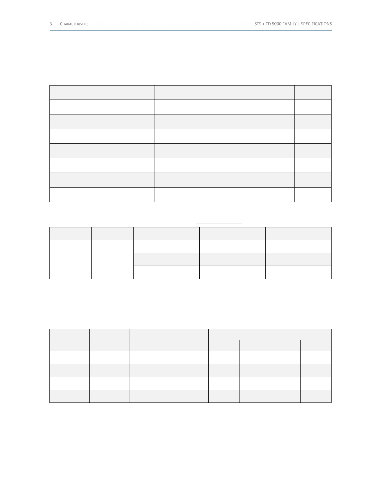
Starting from the internal and external measurements, the test set computes derived measurements, according to the
test selection.
The following table lists the available measurements (the accuracy is the sum of voltage, current and possibly angle
accuracy):
No.
Parameter
AC outputs
Derived from Formula Units
1
Ratio (Rat)
CT or VT or PT
I
out
, Iin or
V
out
, Vin
Rat=I
out/Iin
Rat=V
out/Vin
-
2
Polarity
CT or VT or PT
ϕ I
out
, Iin or
ϕ V
out
, Vin
K => ϕ < 10 ° -
3
Burden
CT and VT
V
out
, I
out
VA=IN2·V
out/Iout
VA
4
Saturation knee
CT
V
out
, I
out
VKn, Ikn: according to the
standards
V, A
5
Resistance
CB and others
I
out
, V
out
R=V
out/Iout
Ω
6
Impedance
CT and VT insulation test
I
out
, V
out
Z=V
out/Iout
Ω
7
Short circuit impedance
PT test
I
out
, V
out
Z=V
out/Iout
H
Table 34 - Available measurements
The following table lists the parameters for the CT, VT and PT ratio measurement:
Range Resolution Ratio range Typical accuracy Maximum accuracy
0÷9,999 1
0.8÷166 0.20% 0.40%
167÷1,666 0.25% 0.50%
1,667÷9,999 0.30% 0.60%
Table 35 - Parameters for CT, VT and PT ratio measurement
For the polarity test, the phase shift between the two parameters is tested. Answer is OK if phase shift is less than 10 °.
The ratio and the polarity are checked also for non-conventional transformers through IEC61850-9-2LE protocol.
For the burden test, the result is the product of voltage and current; the accuracy depends upon the VA range. The
following table lists the parameters for the burden test:
Test voltage
[V]
Test current
[A]
VA range
[VA]
Resolution
[VA]
Typical accuracy Maximum accuracy
% % % %
130 3 3,000 0.05 ±0.1 ±0.1 ±0.2 ±0.2
30 2 300 0.01 ±0.1 ±0.1 ±0.2 ±0.2
10 1 30 0.005 ±0.1 ±0.1 ±0.2 ±0.2
3 1 3 0.001 ±0.2 ±0.1 ±0.3 ±0.2
Table 36 - Parameters for the burden test
Shop for Power Metering products online at:
1.877.766.5412
www.PowerMeterStore.c a
Page 26
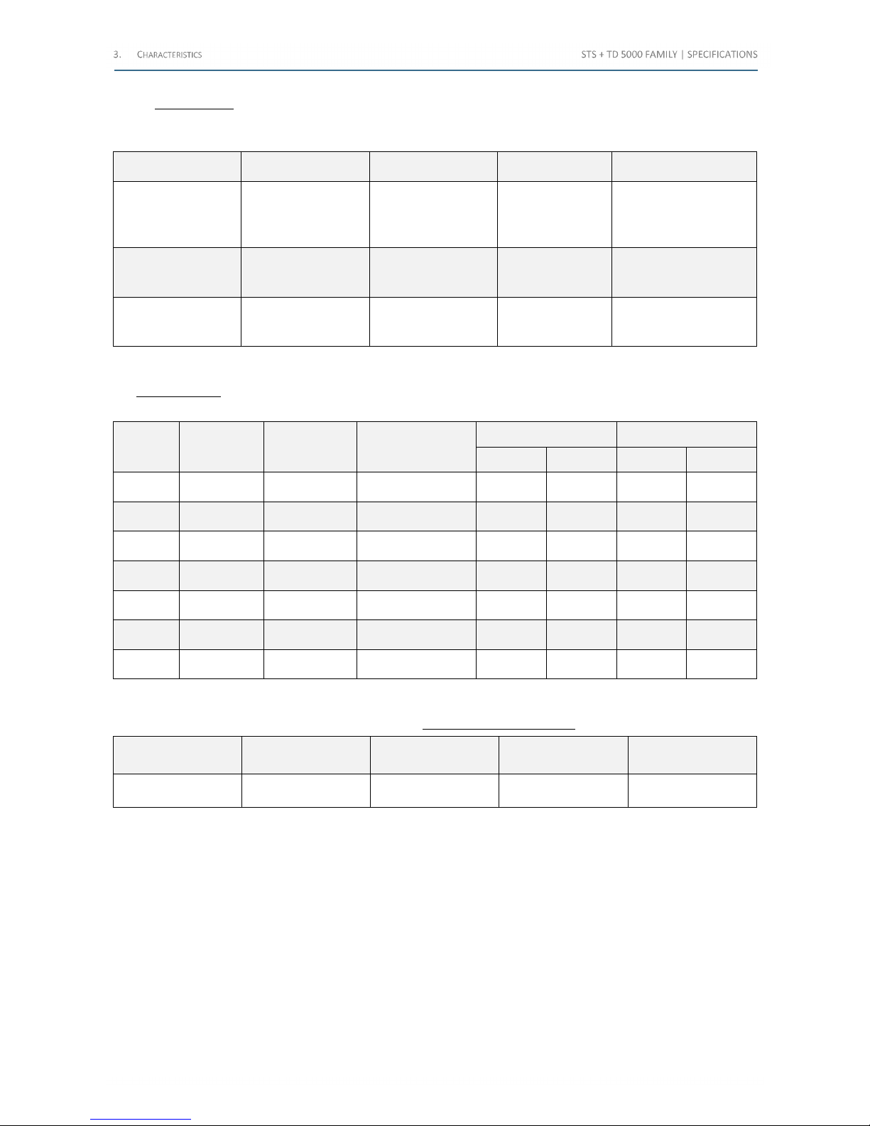
For the resistance test it is possible to perform it with four wires, with the two available DC sources, or with two wires,
using the 10 V measurement input. The following table lists the corresponding range and accuracy (the maximum
resistance is 20 kΩ):
Source Resistance range Resolution Typical accuracy Guaranteed accuracy
High current
400 A
4-wire
10 μΩ
100 μΩ
1 mΩ
10 mΩ
0.01 μΩ
0.1 μΩ
1 μΩ
10 μΩ
< 0.7%
< 0.5%
< 0.5%
< 0.5%
1.35%
1.10%
0.95%
0.95%
Low DC current
6 A
4-wire
100 mΩ
1 Ω
10 Ω
0.1 mΩ
1 mΩ
10 mΩ
< 0.3%
< 0.3%
< 0.2%
0.6%
0.6%
0.4%
DC voltage meter
2-wire
100 Ω
1 kΩ
20 kΩ
0.1 Ω
1 Ω
10 Ω
< 0.6%
< 0.5%
< 0.5%
1.2%
1.0%
1%.0
Table 37 - Resistance test: range and accuracy
The impedance test is performed applying high voltage and measuring the corresponding current. The following table
lists the range and accuracy (the impedance is 100 Ω, the maximum impedance is 2 MΩ):
HV
source
[V]
I output
[A]
Impedance
range
[Ω]
Resolution
[mΩ]
Typical accuracy Maximum accuracy
% % % %
500 0.5÷5 1,000 20 ±0.25 ±0.1 ±0.5 ±0.2
500 0.05÷0.5 10,000 200 ±0.10 ±0.1 ±0.2 ±0.2
1,000 0.5÷2.5 2,000 400 ±0.25 ±0.1 ±0.5 ±0.2
1,000 0.05÷0.5 20,000 2,000 ±0.10 ±0.1 ±0.2 ±0.2
2,000 0.05÷1.25 4,000 800 ±0.25 ±0.1 ±0.5 ±0.2
2,000 0.05÷0.5 40,000 2,000 ±0.10 ±0.1 ±0.2 ±0.2
2,000 0.001÷0.05 2 M 105 ±0.15 ±0.15 ±0.3 ±0.3
Table 38 - Impedance test: range and accuracy
The following table lists the range and tolerances for the short-circuit impedance test:
Measurement range Digits No Range
Maximum
Resolution
Accuracy
10 mH÷2 H 5 Self-adjusting 0.001 mH
1% of the reading,
±0.5 mH
Table 39 - Phase angle resolution and accuracy
Shop for Power Metering products online at:
1.877.766.5412
www.PowerMeterStore.c a
Page 27
3.8 Display
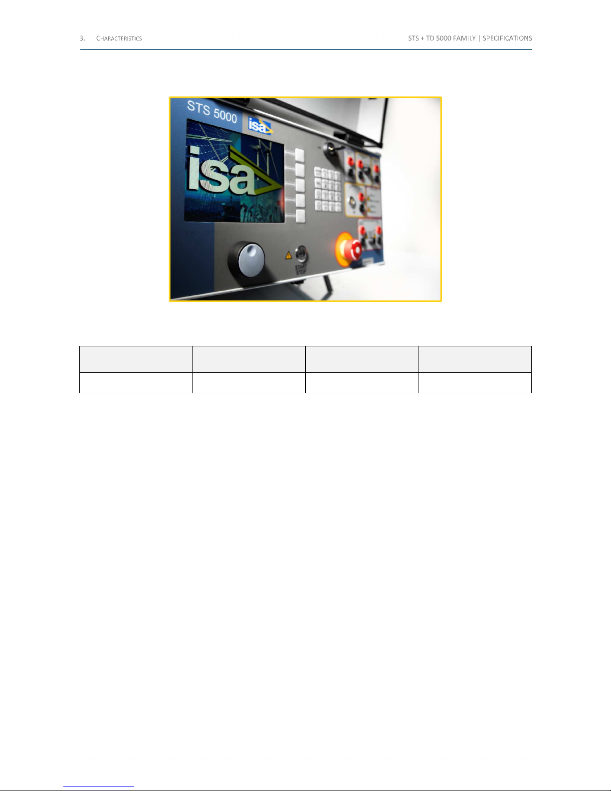
The following image exhibits the STS display:
Figure 5 - STS display
The following table lists the main features of the display:
Pixel Light LCD type View area
640 x 480, colors Backlight TFT 132 x 99 mm
Table 40 - Main features of the display
3.9 Test control
Test control: by the START / STOP pushbutton. Pressing it, the output is generated, after test selection, according to the
type of test. During ON, if a manual control test is selected, the operator adjusts the output at the desired value.
Test saving:
• Automatic save
• After operator confirmation
Shop for Power Metering products online at:
1.877.766.5412
www.PowerMeterStore.c a
Page 28
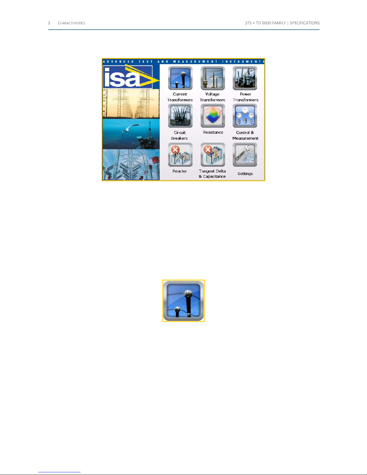
3.10 Menu selections
The following image exhibits the Home page of the test set of the Test Plan Editor:
Figure 6 – Home page
The menu is entered pressing the knob and selecting the item moving the knob.
The Test Plan Editor is an innovative and advanced software module, allowing the operator to define and plan a
sequence of tests. The operator defines the desired sequence of tests and sets the parameters of each test: the Editor
creates a sequence of tests to be performed automatically. The feature is available for the tests of Current, Voltage and
Power transformers.
Test plans can be saved or recalled, like test results. Up to 64 settings can be stored and recalled; setting no. 0 is the
default one, and pops up at power-on. Settings are permanently stored in the memory; new settings can be written to
the same address after confirmation. For normal mode operation it is possible to recall the standard setting, which
cannot be modified.
For instance, in the Home page select the icon “Current Transformers” and press the knob:
Figure 7 – “Current Transformers" icon
Shop for Power Metering products online at:
1.877.766.5412
www.PowerMeterStore.c a
Page 29
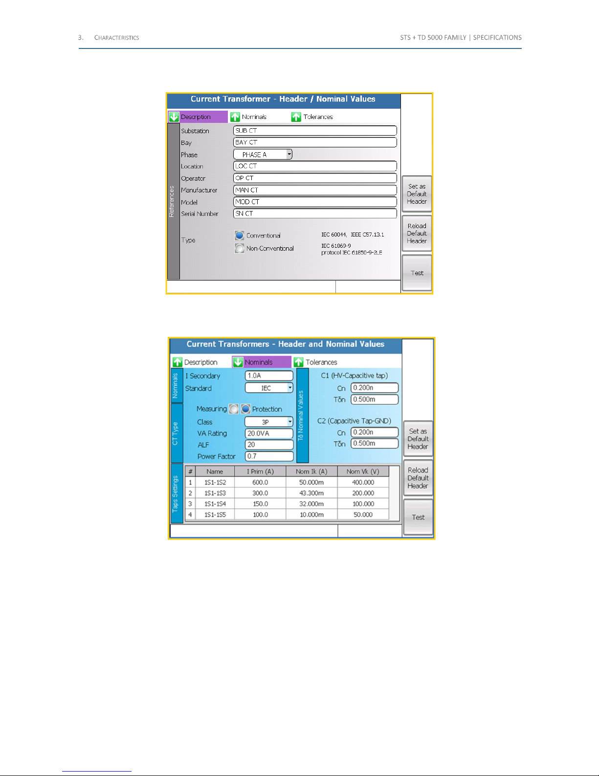
The following image exhibits the “Power Transformers – Header and Nominal Values” page (tab Description), visible at
first time in which entering this section, or pressing the button “Header/Nominal Values”:
Figure 8 - "Current Transformers/Header and Nominal Values" page (tab Description)
The following image exhibits the tab “Nominals” (Conventional Type without the IEC61850-9-2LE output):
.
Figure 9 - "Current Transformers/Header and Nominal Values" page (tab Nominals)
From these nominal data, the program computes the nominal saturation knee.
Shop for Power Metering products online at:
1.877.766.5412
www.PowerMeterStore.c a
Page 30
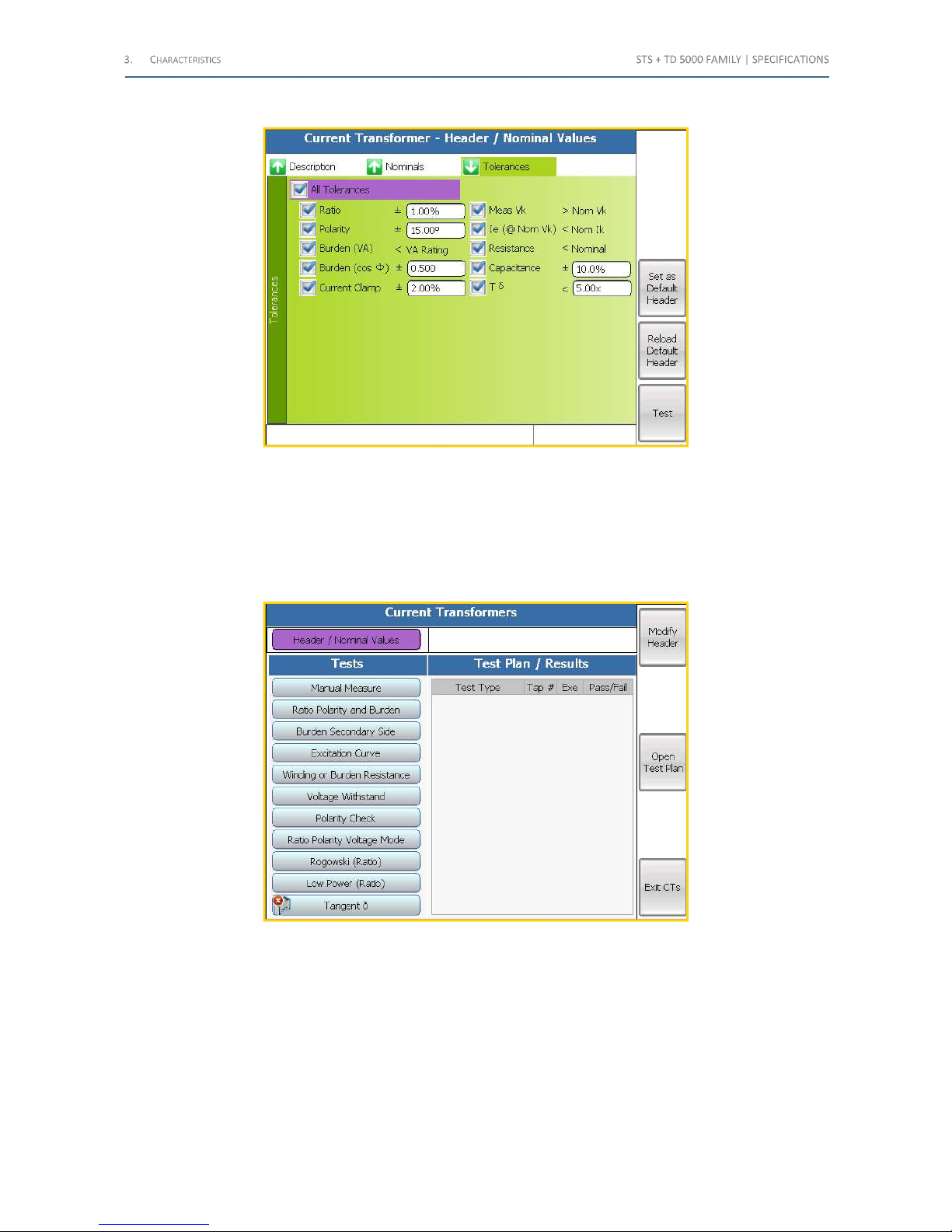
The following image exhibits the tab “Tolerances”:
Figure 10 - "Current Transformers/Header and Nominal Values" page (tab Tolerances)
The page allows setting the tolerances for each of the available tests. If the tolerance is exceeded, the deviation is shown
in the test result table.
After having set this basic information, pressing the shortcut “Edit Test Plan” at the side of the icon and enter the Editor
mode; else, it is possible to continue with a single test.
The following image exhibits the “Current Transformers” test page (Conventional Type):
Figure 11 - "Current Transformers" test page (Conventional Type)
The page allows selecting the test to be performed: the corresponding window is opened, and test parameters can be
programmed
Shop for Power Metering products online at:
1.877.766.5412
www.PowerMeterStore.c a
Page 31
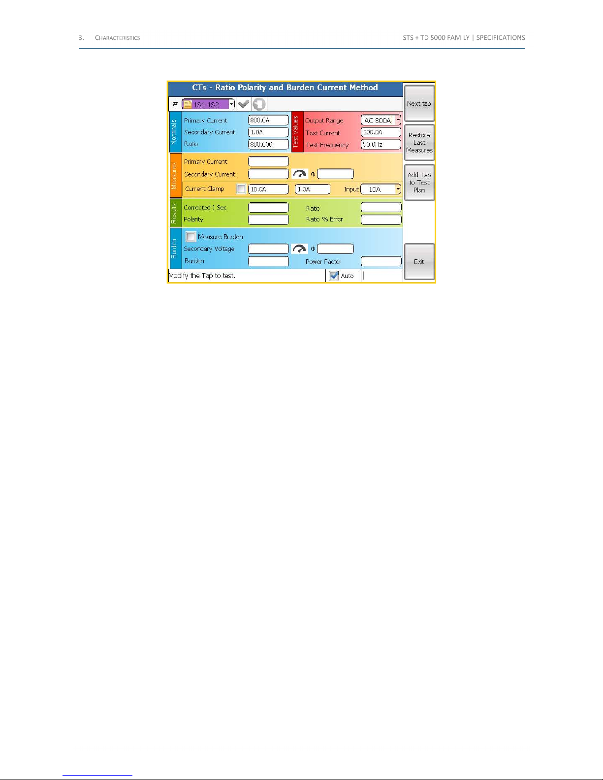
For instance, the following image exhibits the “CTs – Ratio Polarity and Burden Current Method” page:
Figure 12 - "CTs – Ratio Polarity and Burden Current Method" page
As the test programming is finished, pressing the shortcut “Exit” by the side of the icon, it is possible to come back to
the test selection table. Pressing here the shortcut “Exit Ct’s” by the side of the icon, it is possible to come back to the
main menu, and the Editing is finished.
At the end of the programming, starting the first test, the test set executes the complete sequence. During the test, test
results are stored in the memory.
At the end of the tests, settings and results can be downloaded to a PC, with PADS program included in the TDMS suite,
which comes with the device. The software allows saving test results into a file, examining them, printing them.
Optionally, PADS allows controlling the device from the PC. It is also possible to edit settings with PADS, and to upload
them to STS.
In general, the test is performed ramping the parameter until the desired value is reached; after the necessary test
duration, the parameter is reduced to zero.
The following tables summarizes all tests and the corresponding performances.
Shop for Power Metering products online at:
1.877.766.5412
www.PowerMeterStore.c a
Page 32
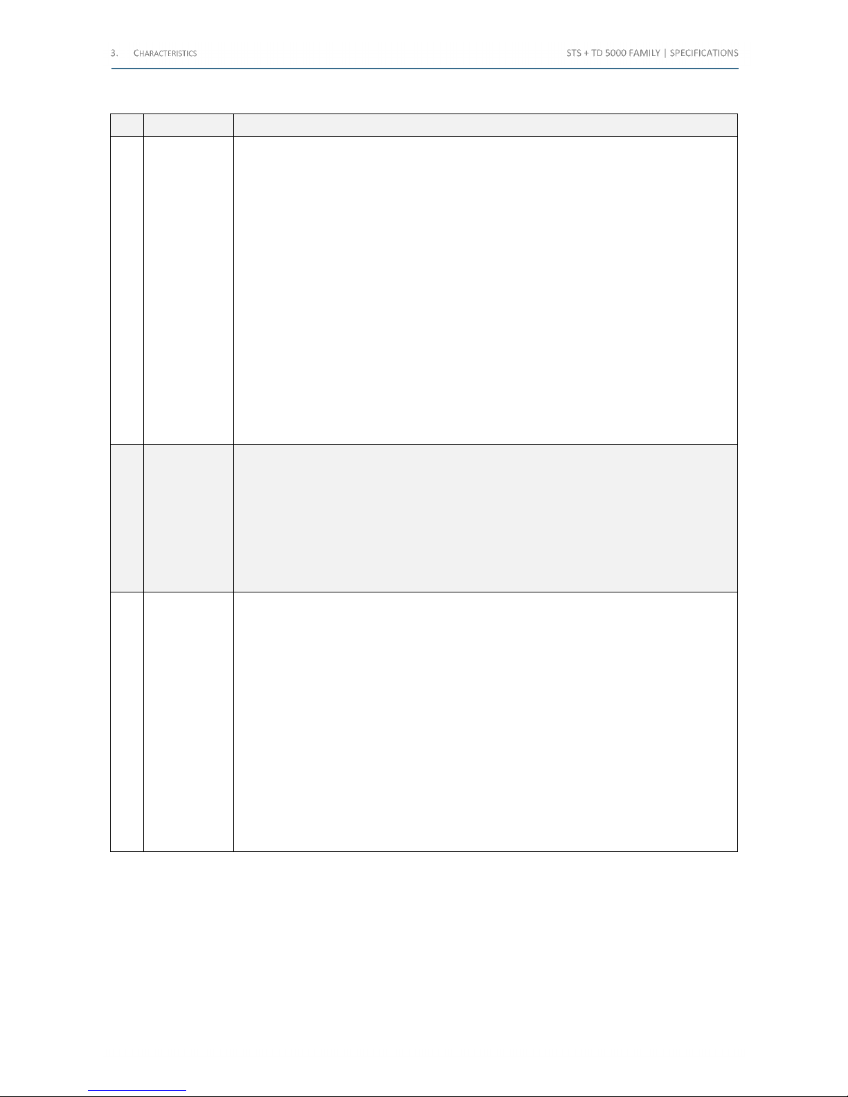
The following table lists the Current Transformers tests:
No. Test Test description
1
Ratio Polarity
and Burden
The ratio measurement is performed applying high current to the CT primary, and
measuring the CT secondary current. The burden can be by-passed, or left in series for the
measurement: in this instance, the voltage drop is measured. The secondary current can be
measured by a clamp.
Input parameters are the following:
• The nominal primary and secondary current, from which the program computes
the nominal ratio
• The nominal test current
The display shows:
• The actual current output
• The corresponding current input, and the value of the secondary current with the
nominal primary current*
• Actual ratio and ratio error
• Phase shift and polarity*
When the burden is tested, the following parameters are displayed
• The voltage drop across the burden
• For the burden: VA rating at the nominal current, angle, power factor
*For Non - CT transformers equipped with IEC61850-9-2LE interface, the STS reads the CT
samples output from its Ethernet interface to measure ratio and polarity
2
Burden
Secondary
Side
The burden measurement is performed applying low AC current to the CT burden, and
measuring the voltage drop.
Input parameters are the following:
• The nominal secondary current
• The nominal test current
The display shows:
• The actual current output
• The voltage drop across the burden
• For the burden: VA rating at the nominal current, angle, power factor
3
Excitation
Curve
The excitation curve is tested connecting the high AC voltage to the CT secondary, slewing
the voltage and measuring at the same time the output voltage and current.
Input parameters are taken from the CT Nominal Values window. Other inputs are the
following:
• Maximum test voltage and current
• Test frequency
The test set controls the output voltage and current during the test, and stops as the knee is
recognized. The display shows the following:
• The characteristic curve
• The actual voltage knee and the error with respect to the nominal
• The actual current error at knee
In addition to this, it is possible to define a point-by-point test, where:
• It is possible to input the desired number of test points, defined with current and
voltage
• The test result reports the deviation from the nominal values, and shows if results
are in the set tolerance
Table 41 - Current Transformers tests (1/4)
Shop for Power Metering products online at:
1.877.766.5412
www.PowerMeterStore.c a
Page 33
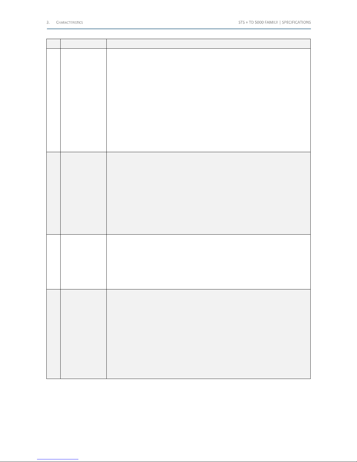
No. Test Test description
4
Winding or
Burden
Resistance
The resistance (not impedance) is measured connecting the low DC current source to
the winding or burden, and measuring the test current and the voltage drop.
Input parameters are the following:
• The nominal resistance
• The connected output
• The test current
• The resistance limits
It is also possible to compensate the test temperature. The test set controls the output
current and voltage during the test, and stops as the test current is reached. The display
shows the following:
• The test current
• The voltage drop
• The measured resistance and the compensated resistance
• The test duration
• The current deviation when the measurement was achieved
5
Voltage
Withstand
The test is performed connecting the high AC voltage source between the CT secondary
cabling and the ground or between the CT primary and secondary.
Input parameters are the following:
• Maximum test current (with automatic switch-off)
• Test time
• Output range
• Test voltage
• Test frequency
The display shows the following:
• During the HV ramping, the test voltage and current;
• As the test is completed, the test voltage, the maximum current, the total
elapsed time, the isolation impedance (not resistance)
6 Polarity Check
The test is performed connecting the high AC current source to the primary side,
generating a special waveform, and measuring the induced secondary current with the
optional PLCK polarity sensor.
Input parameters are the following:
• The test current
• The generation duty cycle
• The test result (OK or NO)
The display shows the test current and records the test result of the different points
7
Ratio Polarity
Voltage Mode
The ratio measurement is performed applying High V AC to the CT secondary, and
measuring the CT primary voltage.
Input parameters are the following:
• The nominal primary and secondary current, from which the program computes
the nominal ratio
• The voltage range
• The nominal test voltage and the test frequency
The display shows the following:
• The current test voltage on the secondary side
• The secondary measured voltage and the secondary current with the nominal
primary current
• Actual ratio and ratio error
• Phase shift and polarity
Table 42 - Current Transformers tests (2/4)
Shop for Power Metering products online at:
1.877.766.5412
www.PowerMeterStore.c a
Page 34
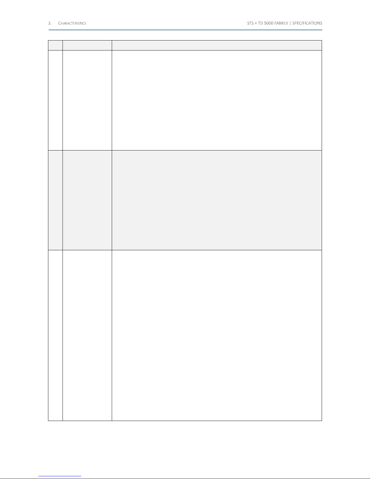
No. Test Test description
8 Rogowski (Ratio)
The test is performed connecting the high AC current source to the primary side, and
connecting the CT secondary side to the low voltage measurement.
Input parameters are the following:
• The nominal primary current and the nominal secondary voltage, from which
the program computes the nominal ratio
• The current range
• The test current
• The test frequency
The display shows the following:
• The nominal primary current and the test current
• The actual test current, the secondary voltage, and the value of the primary
current with the nominal secondary voltage
• Actual ratio and ratio error
• Phase shift and polarity
9 Low Power (Ratio)
The test is performed connecting the high AC current source to the primary side, and
connecting the CT secondary side to the low voltage measurement.
Input parameters are the following:
• The nominal primary current and the nominal secondary voltage, from which
the program computes the nominal ratio
• The current range
• The test current
• The test frequency
The display shows the following:
• The nominal primary current and the test current
• The actual test current, the secondary voltage, and the value of the primary
current with the nominal secondary voltage
• Actual ratio and ratio error
• Phase shift and polarity
10 Tan(δ) measures
The test is performed using the TD 5000 optional module, and then connecting the high
AC voltage source to test target.
Displayed parameters are the following:
• Test type (1): Where the HV output is applied: in case of a specific device under
test (CT, VT, PT or bushing), the options are displayed
• Capacitance (2): In case of a specific device under test (CT, VT, PT or bushing),
the options are displayed
• Generation mode: to execute a single shot, a voltage or a frequency gradient
• Test mode: It is selected in reference to the TD 5000 and the device under test
connection. In case of a specific device under test (VT, in this case), the more
correct test mode is automatically selected, considering also the selections (1)
and (2)
• Voltage/Frequency test table: It allows to input the test voltage and frequency
• Nominal Values: Capacitance and TD reference values. In case of a specific
device under test (CT, VT, PT or bushing), these values are kept from the
related headers
• Temperature compensation: The Capacitance and TD values vary with the
temperature: optionally, the “k” factor is used to compensate the measures
• Test table
• Results table
• Test voltage, current and frequency
• Capacitance, Tan(δ), power factor (PF)
• Power: active, reactive, apparent
• Impedance: module, argument, components
Table 43 - Current Transformers tests (3/4)
Shop for Power Metering products online at:
1.877.766.5412
www.PowerMeterStore.c a
Page 35
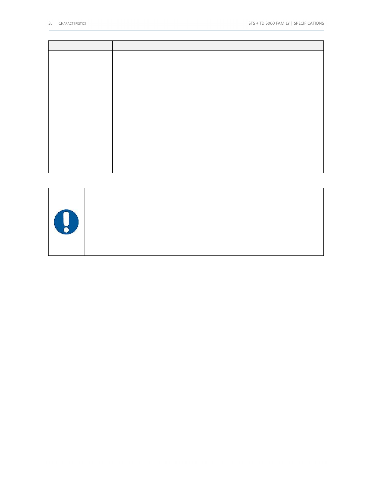
No. Test Test description
11
Ratio IEC61850-9-
2LE
Ratio measure and currents polarity for Not Conventional Transformers. The test is
executed applying current to the primary side and reading the corresponding “Sample
Values”.
The test is executed using the test set remote connection with the PC, using the PDS
program.
Input parameters are the following:
• Nominal primary current
• Test current and frequency
• The sender MAC address
• The recipient MAC address
• The svID (sample value ID)
• The Stream Number
The results are the following:
• The primary current
• The measured Sample Values
• The angle between the primary current and the Sample Values
• Corrected primary current, polarity, error ratio and error %
Table 44 - Current Transformers tests (4/4)
ATTENTION: for the excitation curve test, the following standards apply:
• IEC 60044-1; paragraph 14.4.1. The knee point is the voltage at which the increase of 10% of
voltage causes the increase of the 50% of the exciting current
• ANSI C57.13.1; chapter 9. Plotting a log-log diagram with the excitation current on the X axis
and the exciting voltage on the y axis, the knee point is the one where the tangent of the
curve is at 45°
• ANSI C57.13.1; chapter 9. Plotting a log-log diagram with the excitation current on the X axis
and the exciting voltage on the y axis, the knee point is the one where the tangent of the
curve is at 30°
Shop for Power Metering products online at:
1.877.766.5412
www.PowerMeterStore.c a
Page 36
The following table lists the Voltage Transformers tests:
No. Test Test description
1 Ratio
The ratio measurement is performed applying high voltage to the VT primary, and measuring the VT
secondary voltage.
Input parameters are the following:
• The nominal primary and secondary voltage, from which the program computes the nominal
ratio
• Type of connection (Y or Delta)
• The HV range
• The nominal test voltage and frequency
• The selected voltage meter
The display shows the following:
• The actual test voltage
• The secondary voltage*
• The value of the secondary voltage with the nominal primary voltage
• Actual ratio and ratio error
• Phase shift and polarity*
*For Non-conventional VT transformers equipped with IEC61850-9-2LE interface, the STS reads the VT
samples output from its Ethernet interface to measure ratio and polarity
2
Ratio
Electronics
The ratio measurement is performed applying high voltage to the VT primary, and measuring the lowlevel VT secondary voltage.
Input parameters are the following:
• The nominal primary and secondary voltage, from which the program computes the nominal
ratio
• Type of connection (Y or Delta)
• The HV range
• The nominal test voltage and frequency
The display shows the following:
• The actual test voltage
• The secondary voltage
• The value of the secondary voltage with the nominal primary voltage
• Actual ratio and ratio error
• Phase shift and polarity
3 Burden
The burden measurement is performed applying low AC voltage to the VT burden, and measuring the
corresponding current.
Input parameters are the following:
• The nominal secondary voltage
• The voltage range
• The test voltage and frequency
The test current can also be metered by a clamp.
The display shows the following:
• The actual voltage and current test
The results are the following:
• Performance in VA at rated voltage
• Cos(ϕ)
4
Voltage
Withstand
The test is performed connecting the high AC voltage source between the VT secondary cabling and the
ground or between the VT primary and secondary.
Input parameters are the following:
• Maximum test current (with automatic switch-off)
• Test time
• Output range
• Test voltage
• Test frequency
The display shows the following:
• During the generation, the test voltage and current
• As the test is completed, the maximum current, the total elapsed time, the isolation impedance
Table 45 - Voltage Transformers tests (1/2)
Shop for Power Metering products online at:
1.877.766.5412
www.PowerMeterStore.c a
Page 37
No. Test Test description
5
Polarity
Check
The test is performed connecting the high AC voltage source to the primary side, and
measuring the induced secondary voltage with the optional PLCK polarity sensor.
Input parameters are the following:
• The test voltage
• The generation duty cycle
• The test result (OK or NO)
The display shows the test voltage, and records the test result of the different points
6
Tan(δ)
measures
The test is performed using the TD 5000 optional module, and then connecting the high AC
voltage source to test target.
Displayed parameters are the following:
• Test type (1): Where the HV output is applied: in case of a specific device under test
(CT, VT, PT or bushing), the options are displayed
• Capacitance (2): In case of a specific device under test (CT, VT, PT or bushing), the
options are displayed
• Generation mode: to execute a single shot, a voltage or a frequency gradient
• Test mode: It is selected in reference to the TD 5000 and the device under test
connection. In case of a specific device under test (VT, in this case), the more correct
test mode is automatically selected, considering also the selections (1) and (2)
• Voltage/Frequency test table: It allows to input the test voltage and frequency
• Nominal Values: Capacitance and TD reference values. In case of a specific device
under test (CT, VT, PT or bushing), these values are kept from the related headers
• Temperature compensation: The Capacitance and TD values vary with the
temperature: optionally, the “k” factor is used to compensate the measures
• Test table
• Results table
• Test voltage, current and frequency
• Capacitance, Tan(δ), power factor (PF)
• Power: active, reactive, apparent
• Impedance: module, argument, components
7
Ratio
IEC61850-
9-2LE
Ratio measure and currents polarity for Not Conventional Transformers. The test is executed
applying current to the primary side and reading the corresponding “Sample Values”.
The test is executed using the test set remote connection with the PC, using the PDS program.
Input parameters are the following:
• Nominal primary current
• Test current and frequency
• The sender MAC address
• The recipient MAC address
• The svID (sample value ID)
• The Stream Number
The results are the following:
• The primary current
• The measured Sample Values
• The angle between the primary current and the Sample Values
• Corrected primary current, polarity, error ratio and error %
Table 46 - Voltage Transformers tests (2/2)
Shop for Power Metering products online at:
1.877.766.5412
www.PowerMeterStore.c a
Page 38
The following table lists the Power Transformers tests:
No. Test Test description
1 Ratio
The ratio measurement is performed applying high voltage to the VT primary, and
measuring the VT secondary voltage for each tap. If the STCS option is available, connection
is performed via the option, and the test is completely automatic.
Input parameters are the following:
• The nominal primary and secondary voltage, from which the program computes
the nominal ratio
• Type of connection (Y or Delta)
• The type of Tap changer
• The nominal test voltage and frequency
The display shows the following:
• The test voltage, primary and secondary
• Actual ratio and ratio error
• Phase shift and polarity
2
Winding
Resistance
The test is performed applying low DC current to the PT primary plus Tap Changer and
measuring the voltage drop. The tester measures the resistance peak during the switch and
the resistance after the selection.
Input parameters are the following:
• The nominal resistance
• The output current (6 A or 400 A)
• The test current
• The nominal resistance and the resistance limits
It is also possible to compensate the test temperature.
The test set controls the output current during the test and issues the Tap Change
command. The display shows the following:
• The test current
• The tap number
• For the static resistance: the test voltage and resistance, also compensated
• For the dynamic resistance: the measured values are the Ripple and the Slope and
the diagrams of the current or of the resistance
During the current discharge, voltage and current are displayed.
The dynamic resistance measurement is performed also without the STCS option. The tap
changer command is manual
3
Winding
Resistance –
Auto
The test is performed applying low DC current to the PT primary plus Tap Changer and
measuring the voltage drop. The tester measures the resistance peak during the switch and
the resistance after the selection. Using the STCS option, the connection to the PT is
performed using the option and the test is completely automatic.
Input parameters are the following:
• The nominal resistance
• The output current (6 A or 400 A)
• The test current
• The nominal resistance and the resistance limits
It is also possible to compensate the test temperature.
The test set controls the output current during the test and issues the Tap Change
command. The display shows the following:
• The test current
• The tap number
• For the static resistance: the test voltage and resistance, also compensated
• For the dynamic resistance: the measured values are the Ripple and the Slope and
the diagrams of the current or of the resistance
During the current discharge, voltage and current are displayed.
The dynamic resistance measurement is performed also without the STCS option. The tap
changer command can be automatic
Table 47 - Power Transformers tests (1/3)
Shop for Power Metering products online at:
1.877.766.5412
www.PowerMeterStore.c a
Page 39
No. Test Test description
4
Voltage
Withstand
The test is performed connecting the high AC voltage source between the CT secondary
cabling and the ground or between the CT primary and secondary.
Input parameters are the following:
• Maximum test current (with automatic switch-off)
• Test time
• Output range
• Test voltage
• Test frequency
The display shows the following:
• During the HV ramping, the test voltage and current;
As the test is completed, the test voltage, the maximum current, the total elapsed time, the
isolation impedance (not resistance)
5
Short-Circuit
Impedance
The test is performed applying low AC current to the winding under test, while other
windings are short-circuited, and measuring the associated voltage and phase shift. If the
STCS option is available, connection is performed via the option, and the test is completely
automatic.
• Input parameters are the following:
• The test current and frequency
• The type of winding
• The phase under test
It is also possible to compensate the test temperature. The test set measures the output
voltage, and computes the related parameters. The display shows the following:
• Phase shift; the power loss; the R, X, Z and inductance of the transformer
• The same parameters, but expressed in Per Unit
6
No-Load
Current
The test is performed connecting the TD 5000 optional module (or the HV output), to the
device under test.
Input parameters are the following:
• The test voltage
• The frequency
The test set applies the high voltage and measures the output current during the test. The
display shows the following:
• The test voltage
• The current and the phase shift
• The power losses
• The reactance
Table 48 – Power Transformers tests (2/3)
Shop for Power Metering products online at:
1.877.766.5412
www.PowerMeterStore.c a
Page 40
No. Test Test description
7
Tan(δ)
measures
The test is performed using the TD 5000 optional module, and then connecting the high AC
voltage source to test target.
Displayed parameters are the following:
• Test type (1): Where the HV output is applied: in case of a specific device under
test (CT, VT, PT or bushing), the options are displayed
• Capacitance (2): In case of a specific device under test (CT, VT, PT or bushing), the
options are displayed
• Generation mode: to execute a single shot, a voltage or a frequency gradient
• Test mode: It is selected in reference to the TD 5000 and the device under test
connection. In case of a specific device under test (VT, in this case), the more
correct test mode is automatically selected, considering also the selections (1) and
(2)
• Voltage/Frequency test table: It allows to input the test voltage and frequency
• Nominal Values: Capacitance and TD reference values. In case of a specific device
under test (CT, VT, PT or bushing), these values are kept from the related headers
• Temperature compensation: The Capacitance and TD values vary with the
temperature: optionally, the “k” factor is used to compensate the measures
• Test table
• Results table
• Test voltage, current and frequency
• Capacitance, Tan(δ), power factor (PF)
• Power: active, reactive, apparent
• Impedance: module, argument, components
8 Demagnetizer
Purpose of this test is to apply a DC current with alternate polarity to the winding, in order
to remove from the core the residual magnetism due to a previous winding resistance
measurement.
Input parameters are the following:
• Nominal current (primary and secondary)
• Connections A, B, C according to the vector group
• Transformer side selection
• Output Range
• Test current
The display shows the following:
• DC current and voltage
• Current behavior during the demagnetization procedure
Table 49 – Power Transformers tests (3/3)
Shop for Power Metering products online at:
1.877.766.5412
www.PowerMeterStore.c a
Page 41
The following table lists the Circuit Breakers tests:
No. Test Test description
1
Resistance -
μΩ
The contact resistance test is performed using the high DC current output. The test set
measures the contact resistance down to the µΩ range.
With the same selection, and different generators, it is also possible to measure higher
resistances.
Input parameters are: current output range, test current, and resistance limits. The display
shows the following:
• DC current
• DC voltage
• Resistance
2
Tan(δ)
measures
The test is performed using the TD 5000 optional module, and then connecting the high AC
voltage source to test target.
Displayed parameters are the following:
• Test type (1): Where the HV output is applied: in case of a specific device under test
(CT, VT, PT or bushing), the options are displayed
• Capacitance (2): In case of a specific device under test (CT, VT, PT or bushing), the
options are displayed
• Generation mode: to execute a single shot, a voltage or a frequency gradient
• Test mode: It is selected in reference to the TD 5000 and the device under test
connection. In case of a specific device under test (VT, in this case), the more correct
test mode is automatically selected, considering also the selections (1) and (2)
• Voltage/Frequency test table: It allows to input the test voltage and frequency
• Nominal Values: Capacitance and TD reference values. In case of a specific device
under test (CT, VT, PT or bushing), these values are kept from the related headers
• Temperature compensation: The Capacitance and TD values vary with the
temperature: optionally, the “k” factor is used to compensate the measures
• Test table
• Results table
• Test voltage, current and frequency
• Capacitance, Tan(δ), power factor (PF)
• Power: active, reactive, apparent
• Impedance: module, argument, components
Table 50 - Circuit Breakers tests
Shop for Power Metering products online at:
1.877.766.5412
www.PowerMeterStore.c a
Page 42
The following table lists the Resistances tests:
No. Test Test description
1
Resistance -
μΩ
The contact resistance test is performed using the high DC current output. The test set
measures the contact resistance down to the µΩ range.
With the same selection, and different generators, it is also possible to measure higher
resistances.
Input parameters are: current output range, test current, and resistance limits. The display
shows the following:
• DC current
• DC voltage
• Resistance
2
Earth
Resistance
For the resistivity test, input parameters are the following:
• Voltage range
• Test voltage
• Test frequency
The measurements are narrow filtered in order to reduce the noise, coming from the
environment.
Input parameters are the following:
• Output voltage range
• Test voltage
• Test frequency
The display shows the following:
• Test probe distance
• Output voltage
• Test probe voltage
• Output current
• Phase shift
• Earth resistance
• Evaluation
Ground Resistance Values : from 0.05 Ω to 300 Ω
The test of ground grid resistance is performed applying current between the ground grid and
the auxiliary ground spikes. With the STLG option the test is performed using an overhead line
to connect to the remote ground
3
Soil
Resistivity
The test of soil resistivity is performed applying AC voltage to two spikes, and measuring the
injected current, and the voltage across the voltage spikes.
The display shows the following:
• Location
• Probes distance
• Output voltage
• Voltage between probes
• Output current
• Corresponding resistivity
• Evaluation
Table 51 - Resistances tests (1/2)
Shop for Power Metering products online at:
1.877.766.5412
www.PowerMeterStore.c a
Page 43
No. Test Test description
4
Step and
Touch
The step and touch voltages test is performed applying current between the ground grid and
the auxiliary ground spikes, and measuring the step or touch voltage with the test probes.
With the STLG option, the current generation is performed using an overhead line to connect
to the remote ground. Thanks to the STLG option, higher test currents can be achieved.
Input parameters are the following:
• Substation fault current
• Fault clearance time
• Parallel resistance on the test probes
Other selections are the following:
• Output voltage range
• Test voltage
• Test frequency
With the STLC option, we select the current range. Last, the operator selects the measurement
mode: manual or on STS and the reference standard.
The display shows the following:
• Test current
• Location description
• Location coordinates
• Measured voltage
• Voltage in case of actual fault
5
Line
Impedance
Test parameters are the following:
• Line impedance
• Earth impedance
• Mutual factor
The test is performed applying voltage to the line to be tested, and measuring the
corresponding current and voltage. The test is performed with the STLG option.
Input parameters are the following:
• Type of test
• Phase under test
• Frequency
For the line impedance test, the display shows the following data:
1) Test voltage;
2) Test current;
3) Line impedance, argument, R and X components.
For the earth impedance test, the display shows the following:
• Test voltage and current
• Impedance and argument of: Z, ZL, ZE, earth coefficient KE
For the mutual factor test, the display shows:
• Module and phase of the mutual factor
• ZL module and resistive component
• External voltage, current, phase angle
Table 52 – Resistances tests (2/2)
Shop for Power Metering products online at:
1.877.766.5412
www.PowerMeterStore.c a
Page 44
The following table lists other possible tests:
No. Test Test description
1
Primary and
secondary M.V.
CB and relay
tests
The selection allows injecting the test parameter, and measuring the relay threshold and
trip delay. The tests are feasible using the trigger input logic, or by stopping the test
when the current disappears (M.V. CB). With the option BUX 2000 and BUX 3000 it is
possible to perform high current tests.
Input parameters are the following:
• Current range, output current
• Output voltage
• Frequency
It is possible set the type of digital input (NO-NC, wet-dry, voltage threshold). The display
shows the following data:
• Test current or test voltage
• Trip delay
• External voltage and current measurements
Table 53 – Other possible tests
Shop for Power Metering products online at:
1.877.766.5412
www.PowerMeterStore.c a
Page 45
3.11 Standard connection cables (Long cables code PII16175 and extra long cables code PII57175)
Connection cables differ somewhat as a function of the type of test set. The following table lists cables provided:
Item Description STS 5000 STS 4000
STS 3000
light
1 No 1 Mains supply cable, 2 m long X X X
2
No 1 Grounding cable, 6 m long, 6 mm2, terminated on one side with
a terminator, and on the other side with an earth connection clamp
(No 2 cables for the option PII57175)
X X X
3
No 1 Interface cable for the USB port X X X
4
No 1 ETHERNET interface cable X X X
5
No 1 Operating manuals + Cd-Rom with TDMS X X X
6
No 1 USB pen drive X X X
7
No 6 “Kelvin” clamps, with two sockets: one to connect the current
or voltage; the other one to connect the measurement. Clamp
opening: 60 mm on the rear, 80 mm on the front
X X
8
No 4 Clamps to connect low voltage or low current or
measurements, two red and two black, with a short cable
terminating on a banana socket. Clamp opening: 25 mm
X X
9
No 4 Crocodiles for measurements connections (2 red, 2 black) X X
10
No 1 Short cable, 50 cm long red, terminated with banana sockets on
both sides, for the current measurement of the output 6 A DC
X X
11
No 6 connection cables, three red and three black, 2.5 mm2, 6 m long
(10 m long option PII16175, 15 m long option PII57175), for the
connection of the following: DC current output, low AC voltage
output, digital input. Terminated on both sides with a 4 mm banana
plug
X X
12
No 2 High voltage connection cables, 6 m long (10 m long option
PII16175, 15 m long option PII57175), 5 kV, with earth screen.
Terminated on one side with the HV connector, and on the other
side with a 4 mm banana plug
X X
13
No 2 High current connection cables, 70 mm2, 6 m long (9 m for
option PII16175 and 10 m for option PII57175 [70 mm2, 1 m long +
95 mm2, 9 m long]), for option PII57175). Terminated on one side
with a high current male connector, and on the other side with
spring-loaded clamps, with maximum opening 60 mm
X
14
No 1 Cable for the 10 V or 300 V measurement connection, shielded,
6 m long (10 m long option PII16175, 15 m long option PII57175).
Terminated on one side with three 4 mm banana plugs (two
conductors plus shield), and on the other side with two banana
plugs. Plugs are colored red, black and yellow for the screen
X X
15
No 1 Cable for the 3 V measurement connection, shielded, 6 m long
(10 m long option PII16175, 15 m long option PII57175). Terminated
on one side with the measurement connector, and on the other side
with two banana plugs, red and black
X X
16
N. 1 Transport case for connection Cables X X
Table 54 - Cables provided with the unit
ATTENTION: The previous cables come as standard with the test set; however, they can also be
ordered separately. Optionally, the marked cables can be ordered longer for the option PII16175, or
the option PII57175
Shop for Power Metering products online at:
1.877.766.5412
www.PowerMeterStore.c a
Page 46
3.12 Other characteristics
The following table list other characteristics of the STS:
Item Characteristic Description
1 Memory
• Up to 64 test plans
• More than 1,000 test results
2
Interfaces
• ETHERNET for the PC connection. The Ethernet port can be
used also for remote service and maintenance
• USB port for the USB key: this serves to download test
settings and results
3
Interfaces to external modules
• Commands to TD 5000, STCS and STDE
• Alarms interface from the modules
4
Other interfaces
• Remote Start input. The test is started pressing the button on
the option PII42175
• Safety warning. It can be connected to the strobe with light
PII43175. In case of alarm, the output drives the optional
flashing siren and light
5
Main supply 100÷230 V ± 15%; 48÷62 Hz
6
Power consumption
Less than 1 kW in normal use; 1.8 kW (3,600 VA; 16 A) when
generating the maximum power on High AC voltage output or high DC
current output. For a maximum period of 25 s, the supply power can
be up to 3.6 kW, (7,000 VA; 32 A) when generating the maximum
power on the 800 A output or on the options BUX 2000 and BUX 3000
7
Dimensions
400 (H)x450 (W)x230 (D) mm
STS 5000 weight: 29 kg
STS 4000 weight: 22 kg
STS 3000 light weight: 16 kg
8
Accessories
• User manual, in English, Italian, French and Spanish
• No 5 spare fuses, type T16A
• Connection cables, provided in a case with handle and wheels
Table 55 - Other characteristics of the STS
ATTENTION: If the supply is less than 184 V AC, the test set does not guarantee the full output
power on the 800 A AC output
Shop for Power Metering products online at:
1.877.766.5412
www.PowerMeterStore.c a
Page 47
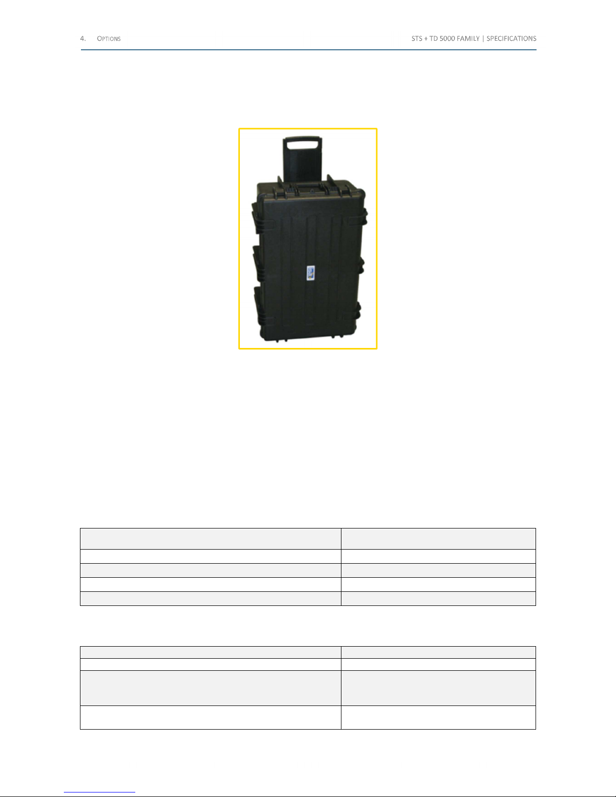
4 O
PTIONS
4.1 Transit cases (code PII17175, PII 19175, PII51175)
The following image exhibits a transit case:
Figure 13 - Transit case
This option applies to all STS models.
There are more types of transit cases:
• one for the STS
• one for TD 5000
• one for RCTD
• one for STLG
• one for BUX 3000
• one for BUX 2000
All of them allow transporting the device. The case has handles and wheels.
The following table lists the Transit case main characteristics:
Characteristic Note
Handling Handles on the top and on the side
Wheel 2
Dimensions 450 x 550 x 850 mm
Weight 15 kg
Table 56 – Transit case main characteristics
The following table lists the Transport cases coding:
Instrument Code
STS
PII17175
TD 5000
RCTD
STLG
PII19175
BUX 3000
BUX 2000
PII51175
Table 57 - Transport cases coding
Shop for Power Metering products online at:
1.877.766.5412
www.PowerMeterStore.c a
Page 48
4.2 PADS licence (code PII10176P, PII10176F, PII10176T)
The software PADS allows connecting to the PC all models of the STS.
Software features are the following:
• To download from the test set test results and settings, and to save them into a file
• To open and save test results in the formats: MDB (ACCESS), XLSX (EXCEL), CSV and JPEG
• To display in real time the measurements performed by the test set, with possibility to pause the test (when
applicable)
• To display, save and print test results diagrams
• To zoom and compare different curves of more than one result
• To edit, display and print the test report, with the following information:
• Place, substation name, line, phase, model, serial number, operator, date and time
• Nominal values: type of device, power, primary and secondary voltage or current
• Parameters tolerances
• For PT’s: nominal tap voltages
• Test result table, with comments about the test results OK or NO
• Notes and comments
The program allows also to do the following:
• Upload or download test settings
• Upload or download test set calibration parameters
PADS software is subject to license, and it is available in three different licenses:
• PADS software Primary - Primary test, CTs and VTs Modules
• PADS Software Transformer - Power Transformer and Tan(δ) Modules
• PADS Full Suite - Primary test, CTs and VTs, Power Transformer and Tan(δ) Modules
ATTENTION: The software runs with any WINDOWS© environment.
Windows, EXCEL and Access are trademarks of Microsoft Corporation
Shop for Power Metering products online at:
1.877.766.5412
www.PowerMeterStore.c a
Page 49
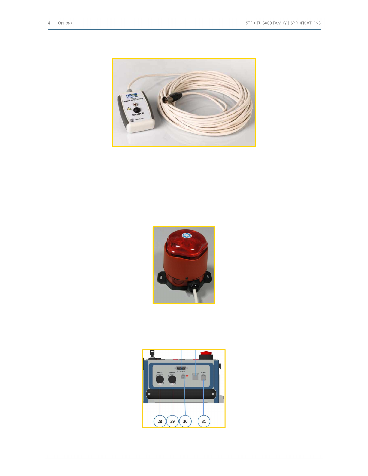
4.3 Remote Safety Switch (code PII42175)
The following image exhibits the Remote Safety Switch:
Figure 14 - Remote Safety Switch
This option applies to all STS models.
When the Remote Safety Switch is connected and enabled, it avoids any current or voltage generation from pressing
START/STOP button on the STS only.
The cable length is 20 m.
4.4 Warning Strobe Light (code PII43175)
The following image exhibits the Warning Strobe Light:
Figure 15 - Warning Strobe Light
This option applies to all STS models.
The Warning Strobe Light alerts when the test is performed. A siren is also included.
It has to be connected to the Safety Warnings (28) connector. The following image exhibits the (28) connector:
Figure 16 - Safety Warnings (28) connector
Shop for Power Metering products online at:
1.877.766.5412
www.PowerMeterStore.c a
Page 50
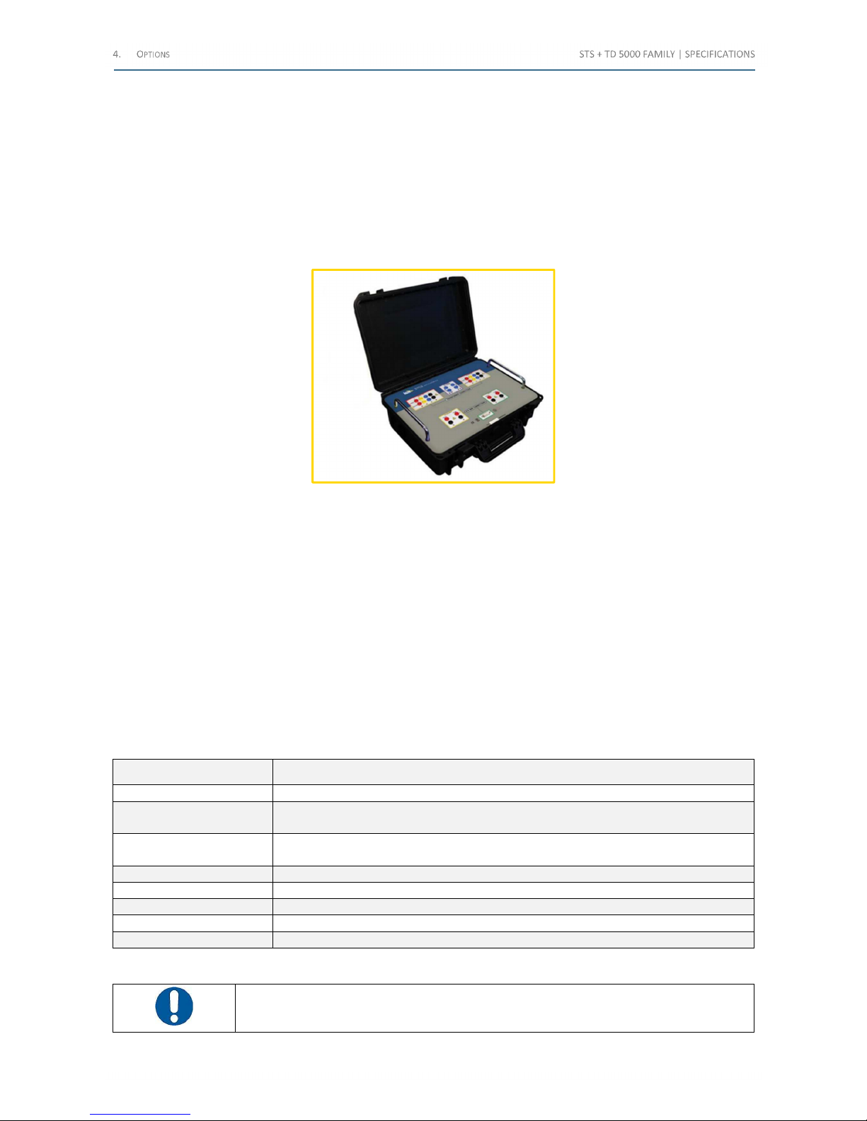
4.5 STCS automatic connection windings module (code PII12175)
This option applies to STS 5000 and STS 4000.
It is applicable when it is necessary to perform one of the following tests on PT:
• Ratio
• Winding resistance
• Short-circuit impedance
• OLTC dynamic test
The following image exhibits the STCS option:
Figure 17 - STCS option
STCS allows performing automatically the tests.
Advantages:
• Fast measurement set-up
• Low probability of connection errors
The STCS option includes the following:
• The input sockets to the STS outputs
• The connections of the active output to the HV or LV sides of the PT under test
• The connection to the STS measurement inputs
• Two relays for the Tap Changer Up and Down commands up to 240 V, 1 A AC, or up to 110 V, 0.1 A DC
• The connector to the STS EXT. DEVICE connector
The STCS option comes complete with the following connection cables:
Cable Characteristics
No. 10 cable reels Marked with different colors, 15 m long
No. 2 High Voltage cables
2 m long, one red and one black, terminated on one side with the HV connector, and on the other
side with 4 mm banana plugs
No. 6 Cables
2 m long, three red and three black, for the connection to: DC current generator, 300 V AC meter,
10 V DC meter. Cables are terminated on both sides with 4 mm banana plugs
No. 1 data cable To the EXT. DEVICES connector of STS, 2 m long
No. 6 adaptors From banana to terminal
No. 8 “Kelvin” type clamps For the connection to the PT bushings
No. 1 Ground cable 6 m long, terminated with terminator and clamp
No. 1 Transport cases
Table 58 – STCS cables
ATTENTION: The cables in the following list come as standard with STCS; they can also be
ordered separately
Shop for Power Metering products online at:
1.877.766.5412
www.PowerMeterStore.c a
Page 51
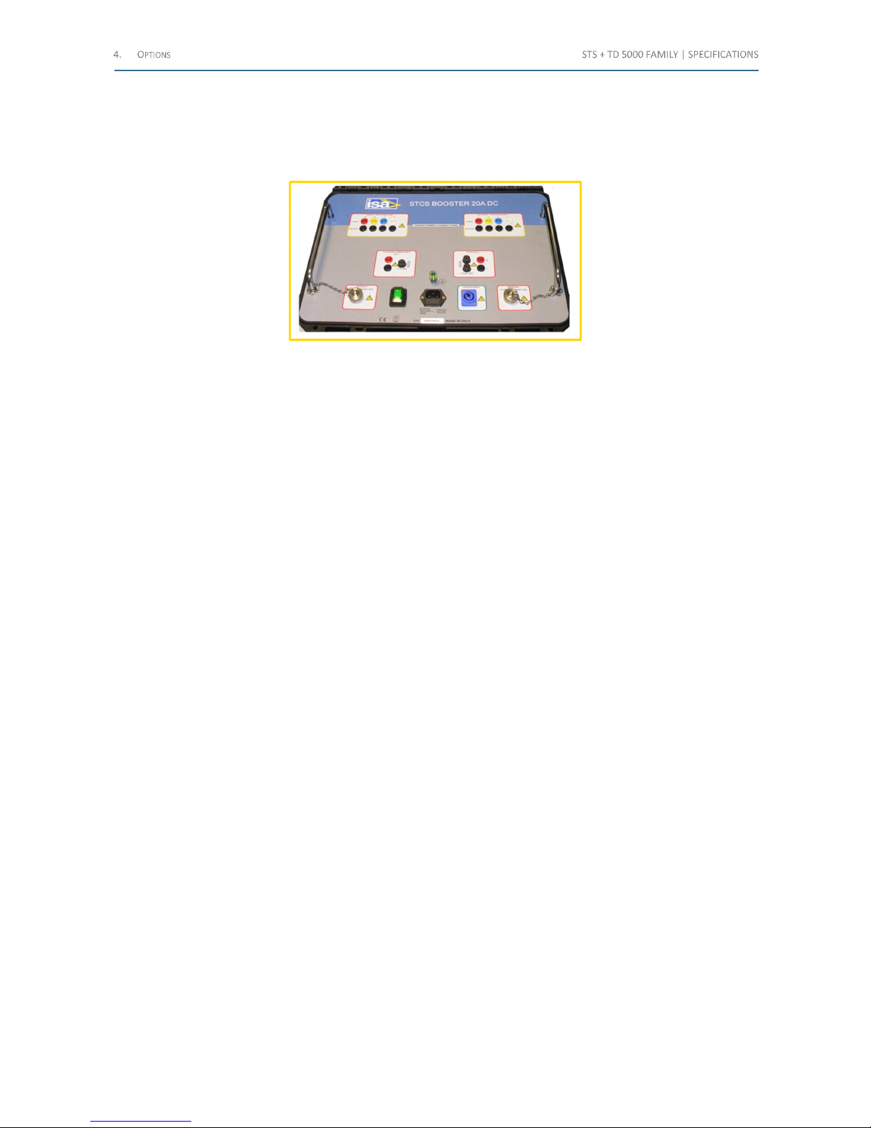
4.6 STCS power generator Booster 20 A DC (code PII32175)
This option applies to STS 5000 and STS 4000 and must be connected to the STCS, which controls the option itself.
The STCS Booster 20 A DC allows to perform winding resistance tests up to 20 A DC on a PT.
The following image exhibits the STCS Booster 20 A DC option:
Figure 18 - STCS Booster 20 A DC option
The module characteristics are the following:
• Maximum output current: 20 A DC
• Maximum power on output sockets: 400 W
• Current output switch: controlled by STCS
• Current output amplitude: controlled by STS 5000 or STS 4000
The option comes complete with the following connection cables:
• No. 2 interface connection cables to STCS
• No. 1 Booster power cable, to connect the option to the STS
• No. 1 Power supply cable
• No. 2 cables, 2 m long, one red and one black
Shop for Power Metering products online at:
1.877.766.5412
www.PowerMeterStore.c a
Page 52
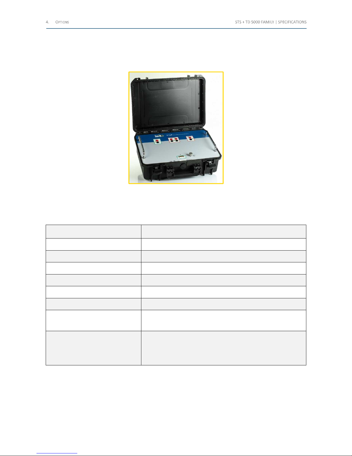
4.7 STDE residual magnetization removal module (code PII27175)
This option allows neutralizing the residual magnetization of the power transformer core after the winding resistance
test. The connection to STS is mandatory.
The following image exhibits the STDE option:
Figure 19 - STDE option
The principle of the option is to apply a DC voltage with alternate polarity to the transformer winding, following the
IEEE 62-1995 standard.
The following table lists the STDE main characteristics:
Characteristic Note
Generator Constant current, voltage limited
Maximum test current 7 A DC
Maximum test voltage 70 V DC
Current resolution 7 mA
Output current stability Better than 0.5% of the rated value
Case Plastic case with handle
Connections
• Connection to the STS control connector
• Two sockets to the STS DC output
• Two sockets to the transformer to be de-magnetized
Cables
• No 1 interface connection cable to STCS, 2 m long
• No 6 Cables, 2 m long, one red and one black, for the connection
to the STS
• No. 2 Cables, 10 m long, for the STDE current output to the
device under test
Table 59 – STDE main characteristics
Shop for Power Metering products online at:
1.877.766.5412
www.PowerMeterStore.c a
Page 53
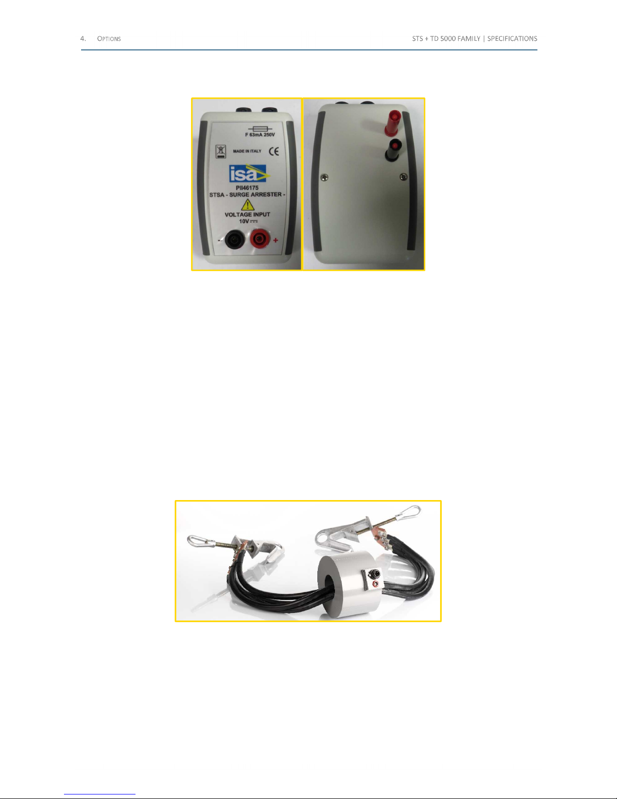
4.8 STSA Surge Arrester (code PII46175)
The following image exhibits the STSA Surge Arrester:
Figure 20 - STSA Surge Arrester
This option applies to STS 5000 and STS 4000.
The option limits voltage surges generated at the DC Voltage input measurement if, during the winding resistance test,
the circuit is erroneously opened. In this event, the sudden opening of a circuit involving a large inductance generates
a high voltage surge, which could disturb the instrument operation, or even damage it.
The option includes a surge arrester plus two fuses. If the impulse has a normal energy, this energy is dissipated by the
surge arrester, and there is no permanent damage; if, instead, the energy is too high, the arrester is short-circuited, and
fuses blow.
The option has the dimensions 35 x 70 x 20 mm; it is connected to STS 10 V measure output with two 4-mm banana
plugs.
4.9 BUX 3000, BUX 2000 current booster (codes PII50175, PII56175)
The optional current boosters BUX 3000 and BUX 2000 allow performing tests up to respectively 3,000 A and 2,000 A.
This option applies to STS 5000 and STS 4000.
The following image exhibits the BUX 3000 option:
Figure 21 - BUX 3000 option
The high current booster option allows performing the following tests:
• Manual measures, whenever AC current is necessary
• CT ratio, polarity and burden
The option includes the connection cable to the CT under test, and the connection clamps.
Shop for Power Metering products online at:
1.877.766.5412
www.PowerMeterStore.c a
Page 54
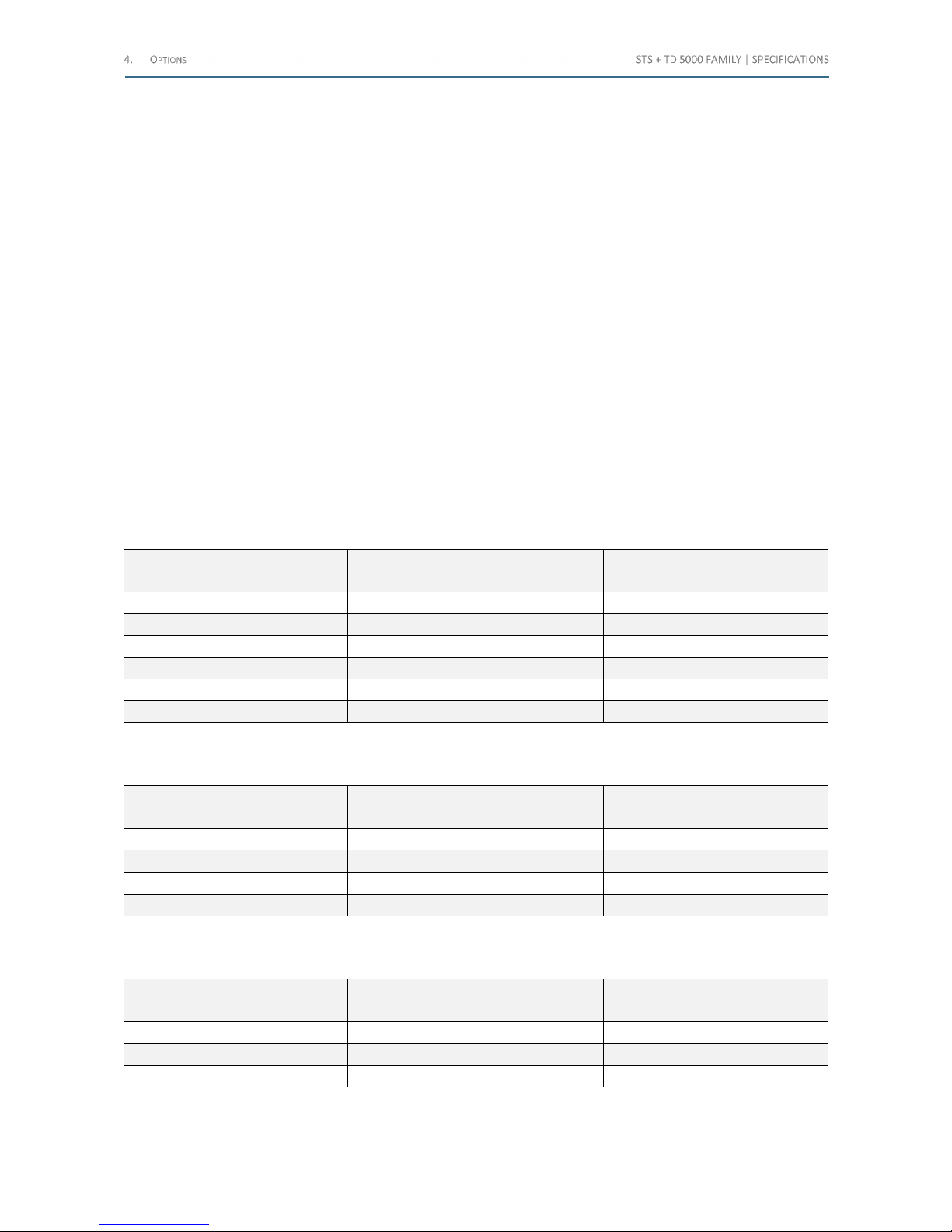
The option avoids wasting power on the connection cables, by putting the power transformers as close as possible to
the test object. This approach is particularly useful when the test is performed on CTs in the field, which are some meters
tall.
Cables:
• No. 1 high current cable, 1.2 m long, made of four cables having cross section of 95 mm
2
, type high flexibility.
Terminated on each side with two high current clamps for the connection to the bar, having the following
characteristics:
• Material: aluminum
• Opening range: from 5 to 60 mm
• Short-circuit current rating: 41 kA ÷ 1 s
• Applicable standard: EN 61230
• Hole to lift the clamp to the gate, and ring to tight from the bottom
• No. 1 Voltage supply cable, 20 m long, 2 wires. Terminated on one side with the STS EXT. BOOSTERS connector and
on the other side with the connector for the BUX 3000 module
• No. 1 Metering cable, 20 m long, 2 wires. Terminated on one side with the STS 3 V AC input connector and on the
other side with the connector for the BUX 3000 module The cable includes a shunt, which converts the output
current into voltage
• No. 2 Metering cables, 2 m long, terminated on both sides with 4 mm banana plugs, for the connection of the STS
Current input to the CT secondary
The following table lists the maximum test currents and durations for the power supply of 230 V for BUX 3000:
Test current
[A]
Output power
[VA]
On duration
[s]
500 300 Infinite
1,000 900 Infinite
1,500 1,500 1,200
2,000 2,400 300
2,500 3,400 120
3,000 4,800 60
Table 60 - Max test currents and durations (230 V) for BUX 3000
The following table lists the maximum test currents and durations for power supply of 110 V for BUX 3000:
Test current
[A]
Output power
[VA]
On duration
[s]
500 300 Infinite
1,000 900 Infinite
1,500 1,500 1,200
2,000 2,400 300
Table 61 - Max test currents and durations (110 V) for BUX 3000
The following table lists the maximum test currents and durations for power supply of 230 V for BUX 2000:
Test current
[A]
Output power
[VA]
On duration
[s]
500 700 Infinite
1,000 1,500 60
2,000 5,000 25
Table 62 - Max test currents and durations (230 V) for BUX 2000
Shop for Power Metering products online at:
1.877.766.5412
www.PowerMeterStore.c a
Page 55
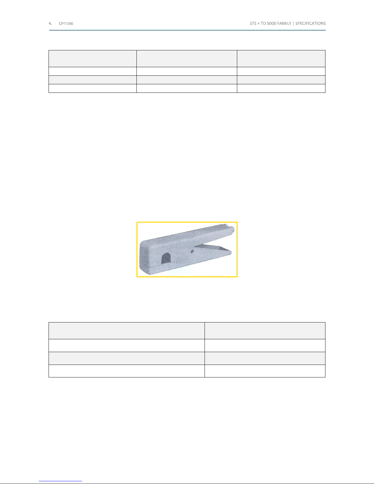
The following table lists the maximum test currents and durations for power supply of 110 V for BUX 2000:
Test current
[A]
Output power
[VA]
On duration
[s]
500 700 Infinite
1,000 1,500 600
1,300 2,400 200
Table 63 - Max test currents and durations (110 V) for BUX 2000
BUX 3000 and BUX 2000 characteristics are the following:
• Output current metering ratio: 1000/1 A
• Accuracy class: typical ±0.1% of reading ±0.1% of range; guaranteed ±0.2% of reading ±0.2% of range
• Module power cable, 20 m long, terminated with connectors on both sides
• Module CT cable, 20 m long, terminated with connectors on both sides
• BUX 3000 weight: 16 kg
• BUX 2000 weight: 18 kg
• Cable and clamps weight: 8.2 kg
• Dimensions: external diameter 190 mm; height 120 mm
4.10 Current Clamp (code PII16102)
The following image exhibits the Current Clamp option:
Figure 22 - Current Clamp
This option applies to STS 5000.
The current clamp avoids opening the secondary current circuit when performing the primary test of CT burden.
The following table lists the Current Clamp main characteristics:
Characteristic Value
Ratio 1 A//1 mA
Maximum primary current 100 A
Maximum cable diameter 12 mm
Table 64 - Current Clamp main characteristics
Shop for Power Metering products online at:
1.877.766.5412
www.PowerMeterStore.c a
Page 56
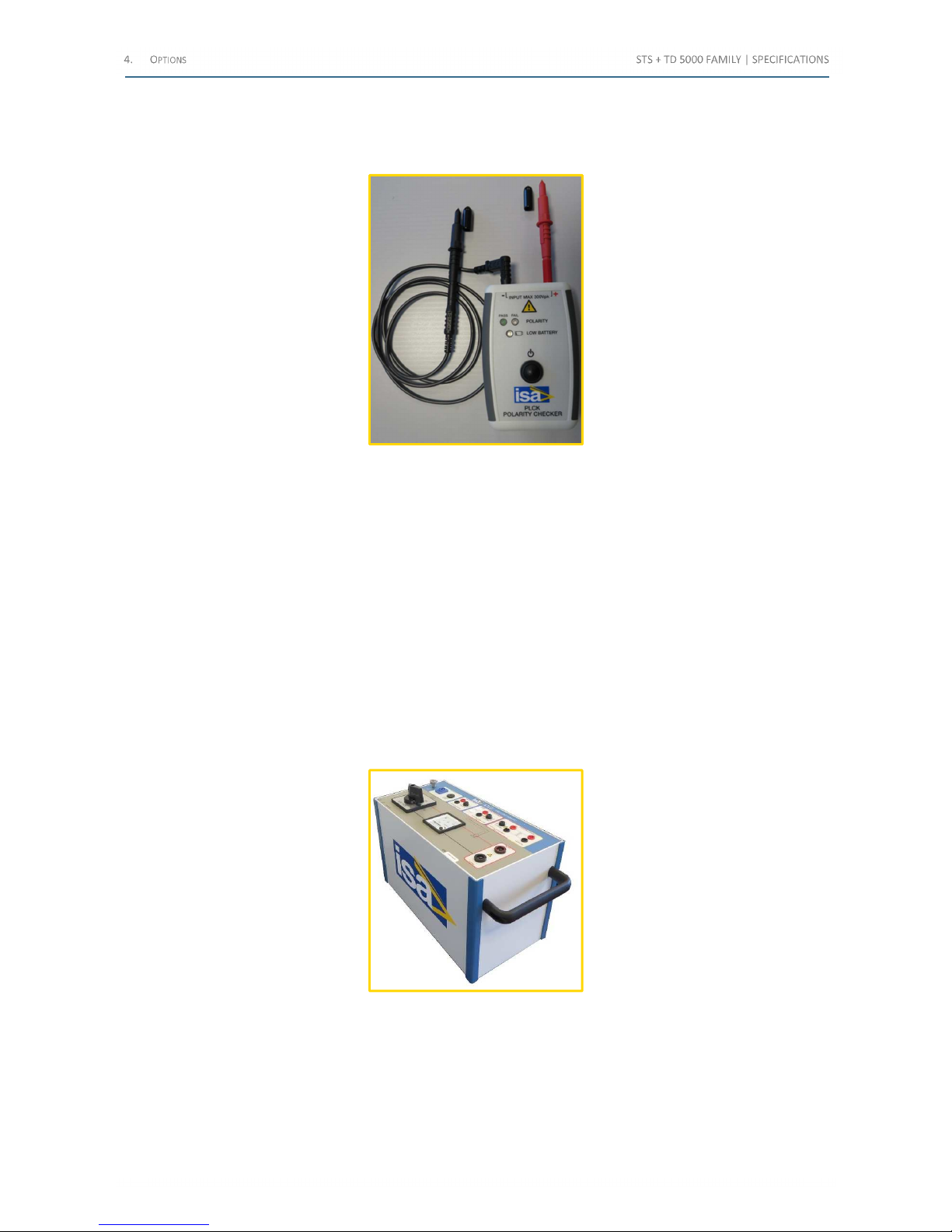
4.11 PLCK Polarity Checker (code PII41175)
This option applies to STS 5000 and 4000 models.
The following image exhibits the PLCK option:
Figure 23 - PLCK option
The PLCK Polarity Checker has three colored LED:
• Pass (GREEN).Indicates the right polarity
• Fail (RED).Indicates the wrong polarity
• Low Battery (BLUE). If it blinks, the battery has reached the first low voltage threshold; the fixed light indicates
the second low voltage threshold, in this case the battery should be changed
The detection range of the PLCK Polarity Checker is from 40 mV to 300 V. If a low or distorted signal is detected, both
Pass and Fail LEDs blink. To check the polarity on a very low impedance (e.g. the current terminals of a numeric relay),
is possible that the voltage drop is much less than 40 mV even when the maximum possible current is generated; in this
case check the polarity including the connection cables to the relay, in order to increase the voltage drop.
4.12 STLG current injection power transformer for ground tests (code PII70175)
This option applies to STS 5000 and 4000 models.
The following image exhibits the STLG option:
Figure 24 - STLG option
It is a high power, five taps transformer, which acts as an impedance adaptor, increasing the impedance at high test
currents. A high current switch allows selecting the desired current range. A voltage meter displays the generated
voltage or the voltage on the line due to the inductive couplings.
Output current and voltage are measured and sent back to STS measuring inputs; a third output allows STS to
understand which one is the selected range.
Shop for Power Metering products online at:
1.877.766.5412
www.PowerMeterStore.c a
Page 57
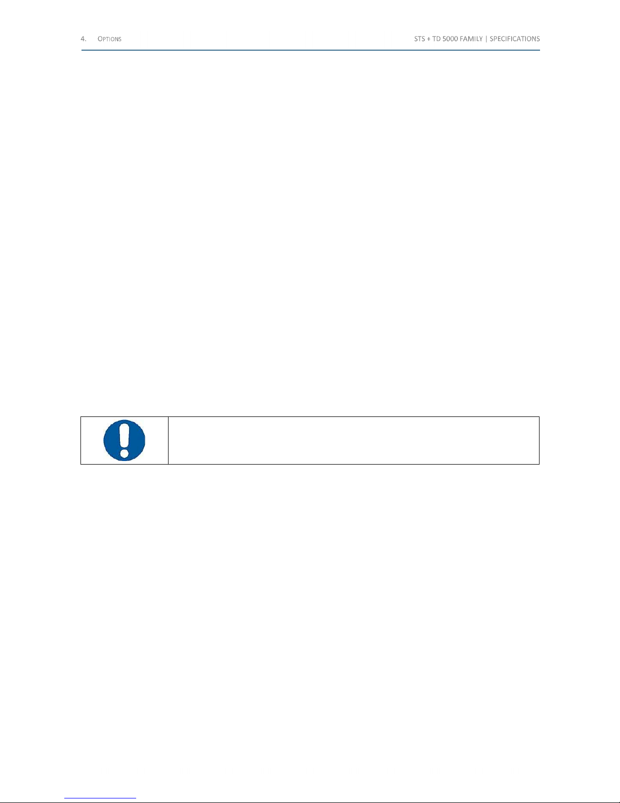
The STLG option characteristics are the following:
• Input: form STS 5000, via the booster connector
• Output current ranges: 11, 22, 35, 55, 105 A AC. Corresponding no-load voltages: 540, 270, 160, 108, 55 V
• Output current connection: via high current sockets
• Output power: 1,800 VA steady; 5,500 VA peak for 5 s, 5,200 VA on the 105 A range
• High current selector switch, to connect the selected tap to the output current sockets
• Analogue voltage meter, to display the voltage at the output sockets. Range: 600 V AC
• Outputs to STS:
• Selected current output range, to the 10 V voltage input
• Output current, to the 10 A current input
• Output voltage, to the 300 V voltage input
• Transport case: black plastic case, with handles
• Weight: 25 kg
• Dimensions: 23 x 33 x 44 cm
All the followings connection cables are included in the option:
• No. 1 Cable, 6 m long, for the connection of the STS BOOSTER connector
• No. 2 Cables, 6 m long, for the current output connection, terminated with “Kelvin” type clamps
• No. 6 cables, red and black, 6 m long
• No. 1 cable for the connection of the STLG voltage meter output to the STS 300 V meter
• No. 1 bridge, to short circuit the current meter output if it is not connected to STS
• Cable transport case
ATTENTION: For safety reasons, STLG must always acts together with the STSG option
4.13 Power factor correction module (code PII85175)
This option is applicable only the STLG option. It is a module to increase the current in the grounding and step and touch
tests; the module has many capacitors and it allows to reduce the reactive component of the line, to obtain the
increasing of the STLG test generated current.
• Dimensions: 325L, 295A, 285P. Aluminum case with handles
• Weight: 12 kg
• Selectable capacitance nominal values: 600 μF, 400 μF, 200 μF, 150 μF and 100 μF
• Maximum voltage: 600 V (range 100 μF and 150 μF) , 450 V on the others
• Maximum current: 60 A
Shop for Power Metering products online at:
1.877.766.5412
www.PowerMeterStore.c a
Page 58
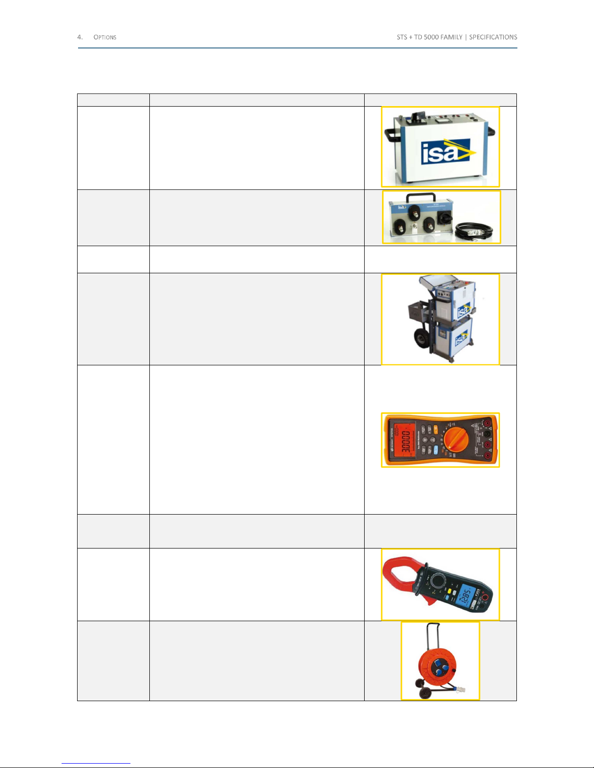
4.14 STLG large station (code PII88175)
The following image lists the kit elements:
Element Description Photo
STLG
PII80175
• Transport case with wheels PII19175
• Standard cable kit PII75175 with case
STSG
PII71175
• N°3 cable connection studs (diameter 20 mm)
PII72175
• N°3 surge arresters (N°3x PII77175
• Transport case with wheels
.
RCLG
PII85175
• Cable for series connection to STLG
• Transport case with wheels
Transport trolley
N°1 Stainless steel stransport trolley PII18175 for the
handling of the test set and of the STLG option
Portable
Handheld
Multimeter
N°1 Mod. KEYSIGHT U1271A
• Count up to 30,000 (4 digits 3/4)
• Analogue scale display
• Impedance 10MR
• Measures TRUE RMS and CC of Ampere, Volt; it
measures Hertz, Ohm, mOhm, mA, capacitance
and temperature
• Operating temperature (-20÷+55) °C; humidity
0÷80%
• CAT III 1000 V; CAT IV 600 V
• Accuracy V CA 0.7% + 20 counts
• Accessories: probes, hermocouple, 4 AAA
batteries, calibration certificate, quick start guide
Step and touch
resistive selector
with active filter
N°1 Box with resistances 1kR for multimeter which
includes an active filter to make the measurements of
step and touch voltage at 80 Hz. Code PII87175
Clamp meter
with multimeter
N°1 Mod. Chauvin Arnoux F203
• Measures CA TRUE RMS, MISURA CC
• Voltage measure CAT III 1000V
• Scale 60 A e 600 A AC; 60 A, 600 A e 900 A in CC
Accuracy 1% up to 599.9 A AC e 900 A CC
• Opening 34mm
Power cable
N°1 Power cable for control units, 2,5 mm2 section,
50 m long, mounted on cable reel with wheels
Table 65 – Kit elements (1/2)
Shop for Power Metering products online at:
1.877.766.5412
www.PowerMeterStore.c a
Page 59
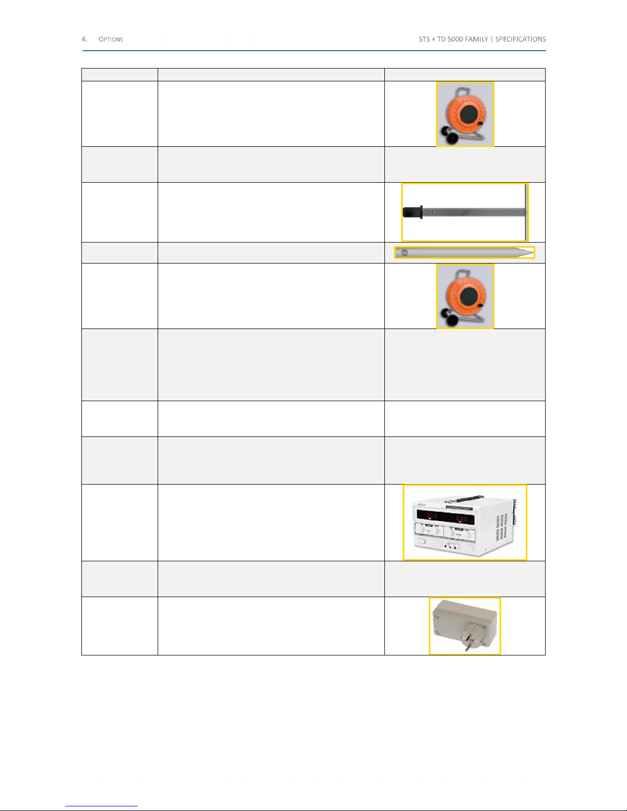
Element Description Photo
Additional
power cables
N°2 exible cables, cross section 10 mm2, 50 m long, for
the connection of the power output, mounted on the
cable-winding with wheels
Measure cables
N°10 cables, 2,5 mm2, 100 m long, each mounted on
its reel; terminated with banana and with securing
sleeve 4 mm
250 N
electrodes
N°2 probes platform, with weights up to 250 N
Tip electrodes N°2 tip electrodes, 0,5 m, with 4 mm sockets
Grounding cable
N°1 cable, 16 mm2, 25 m long, yellow green, mounted
on its reel with wheels
Clamps
• N°3 phase clamps in light alloy with clamping up to
65 mm, with stem ring for laying and removal of
cylindrical conductors from 5 mm to 65 mm
(diameter)
• N°1 Grounding clamp, with tightening capacity up
to 35 mm on cylindrical conductors
Switching Stick
Kit
N°1 Kit compliant to CEI EN 61230, CEI EN 61235, CEI
EN 60855, CEI EN 50508; in three parts, for voltages
≤380 kV
Connection
cables for phase
clamps
N°3 Cable 10 m, section 10 mm2; terminated on one
side with lugs for connection to phase clamps and the
other side with clamps suitable for the connection with
STSG
Stabilized power
supply
N°1 stabilized power supply, input voltage 230 V 50 Hz,
output voltage 0÷30 V CC 0÷20 A
PII86175
Power cable
reels
N°2 flexible cables 50 m long, section 2,5 mm2. Lug
2P+T 16A 230V IP44; 2 sockets 2P+T 16A 230V IP44; 1
German/bi-pass socket 2P+T 16A IP44 + circuit breaker
Line
synchronization
N°1 Line synchronization PII24156
Table 66 – Kit elements (2/2)
Shop for Power Metering products online at:
1.877.766.5412
www.PowerMeterStore.c a
Page 60
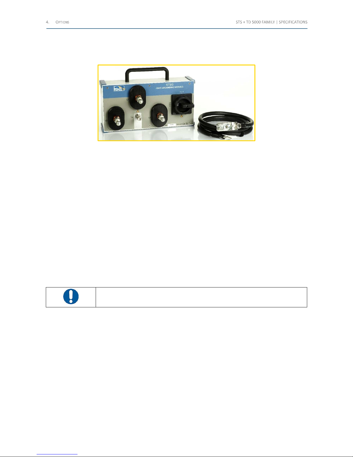
4.15 STSG safety grounding module (code PII71175)
This option applies to STS 5000 and STS 4000; it is used with the STLG option, to increase the operator safety.
The following image exhibits the STSG option:
Figure 25 - STSG option
During tests, STLG is connected to the out of service overhead line to be tested. The purpose of the STSG device is to
protect the operator against possible high voltage spikes during the operations.
STSG incorporates three voltage suppressors (one for each line) and one high current switch, to connect the three lines
in parallel when necessary.
The STSG option characteristics are the following:
• Nominal AC spark-over voltage : <1,000 V
rms
• Impulse spark-over voltage : <2,000 V
peak
• Short-circuit proof with 25 kA
eff
/100 ms; 36 kA
eff
/75 ms
• Connection via three cylindrical studs 16, 20 or 25 mm diameter, for the clamps connection. Each stud is
connected to the voltage suppressor. The stud dimensions must be specified at order
• Tightening torque: ≥15 Nm
• Metallic aluminum box with handle
• Weight: 9.1 kg (with grounding cable)
• Dimensions: 41 x 21 x 13,5 cm
• Grounding cable, included: 95 mm
2
, 2m; terminated with a universal clamp
The device must be connected to the ground and to the HV line.
ATTENTION: Connection cables to the HV line are not included in the option
Shop for Power Metering products online at:
1.877.766.5412
www.PowerMeterStore.c a
Page 61
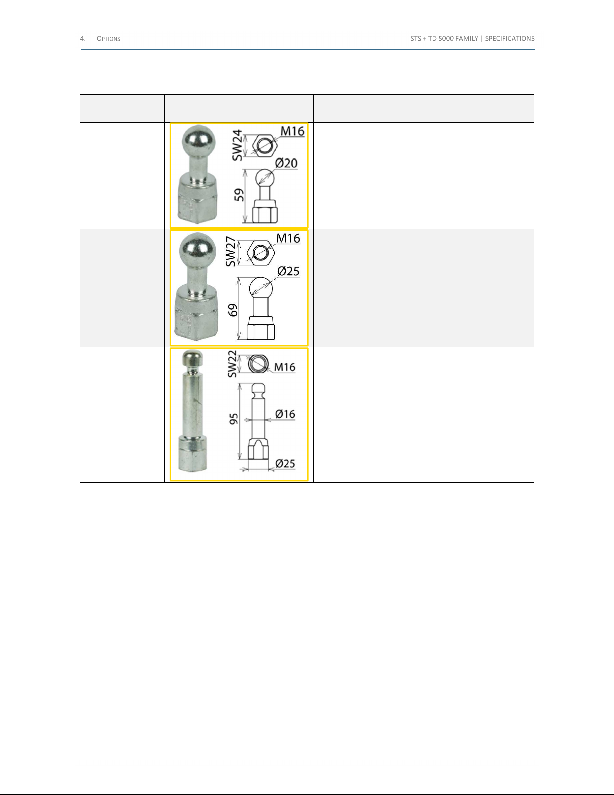
4.15.1 Cylindrical studs
The following table lists the studs for the STSG option:
Stud code Drawing Characteristics
PII72175
max short circuit current:
0.5 s: 33.5 kA
max short circuit current:
1.0 s: 23.7 kA
PII73175
max short circuit current:
0.5 s: 42.0 kA
max short circuit current:
1.0 s: 29.6 kA
PII74175
max short circuit current:
0.5 s: 42.0 kA
max short circuit current:
1.0 s: 29.6 kA
Table 67 - Studs characteristics
4.15.2 Surge arrester for STSG (code PII77175)
If a high voltage spike occurs on the line during the execution of the tests, the STSG surge arresters must be replaced.
Technical characteristics:
• Nominal AC spark-over voltage : < 940 Vrms
• Impulse spark-over voltage : < 1,600 Vpeak
• Short-circuit proof with 25 kAeff/100 ms; 36 kAeff/75 ms
Shop for Power Metering products online at:
1.877.766.5412
www.PowerMeterStore.c a
Page 62
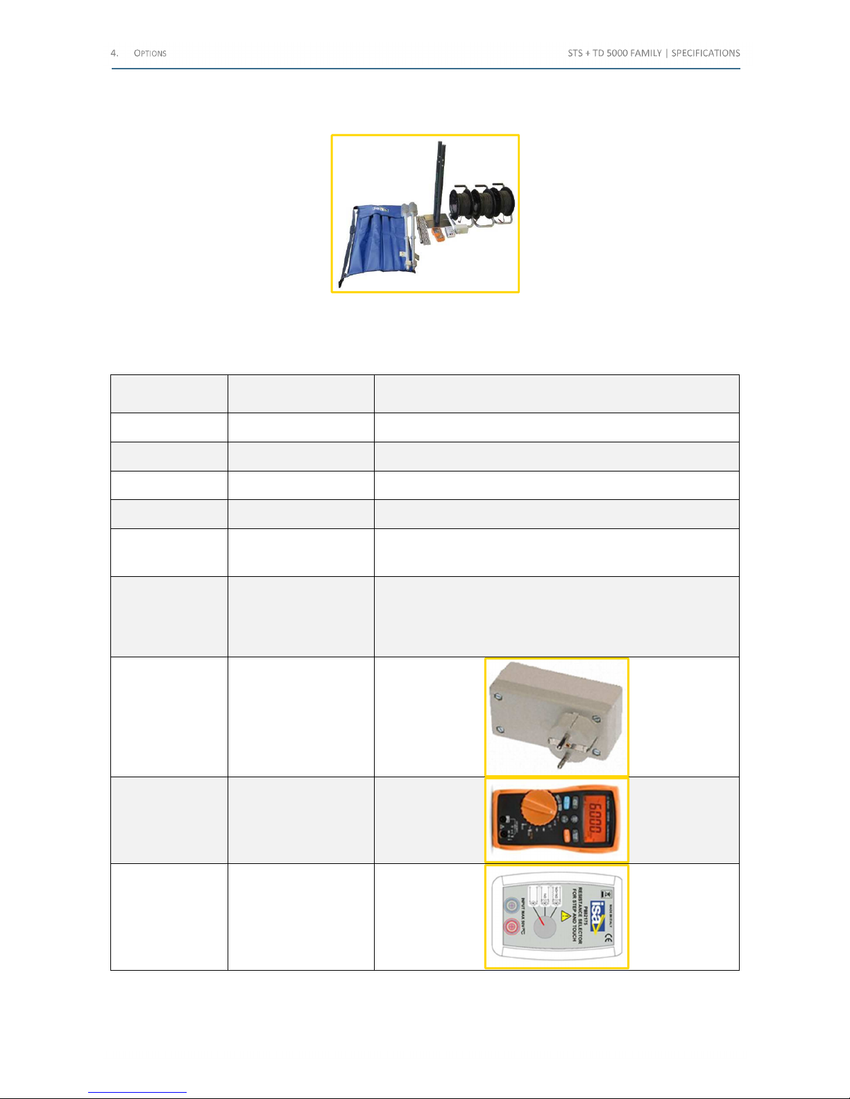
4.16 Ground Grid Test Accessories Kit (code PII76175)
The following image exhibits the Ground Grid Test Accessories Kit:
Figure 26 - Ground Grid Test Accessories Kit
This option applies to STS 5000 and STS 4000 models.
The following table lists the elements of the Ground Grid Test Accessories Kit:
Quantity Element Characteristic
2 Earth Screw
0.95 m long, with 4 mmm sockets
1 Spanner To screw the spike into the ground
4 Earth electrode 0.5 m long, with 4 mmm sockets
1 Transport bag To carry earth spikes, electrodes and spanner
3 Cable
1.5 mm2, 200 m long, mounted on reel, terminated on one side
with safety 4 mm socket and on the other side with safety 4 mm
banana plug
2 Rectangular probe
With shaft 0.8 m long, with safety 4 mm sockets. Material: zincplated iron, dimensions 250 x 120 mm, thickness 10 mm, with
rubber protection on the foot, on the rod and on the handle, and
two safety sockets. The surface in touch with the ground is
limited to 300 cm2
1 Line synchronizer
1
Digital multimeter
CAT III 600V, TRUE RMS,
Accuracy AC ±1 % +3
digits
1
Resistance selector for
Step and Touch test
Table 68 - Elements of the Ground Grid Test Accessories Kit
Shop for Power Metering products online at:
1.877.766.5412
www.PowerMeterStore.c a
Page 63

4.17 Current Clamp Meter (code PII79175)
The following image exhibits the current clamp meter:
Figure 27 – Current Clamp Meter
When it is necessary to use the STSG and STLG options to execute the test, the options are connected to a transmission
line. The line is put out of service, and connected to earth on both sides. Before connection to the HV line, it is necessary
to measure the current flowing into the ground connections, using a clamp meter, to evaluate the residual voltage
coupling.
The following table lists the Current Clamp Meter main characteristics:
Characteristic Value
Maximum current 400 A AC
Digits 4
Accuracy ± 2 % + 5 digits
Clamp opening 37 mm
Table 69 - Current Clamp Meter main characteristics
Shop for Power Metering products online at:
1.877.766.5412
www.PowerMeterStore.c a
Page 64
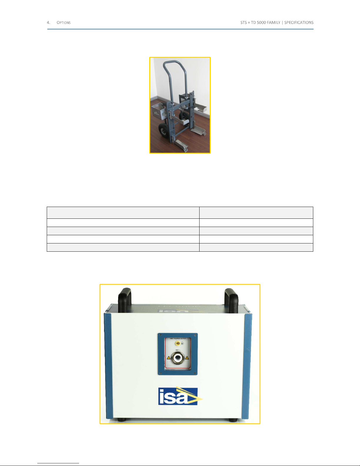
4.18 Foldable Trolley (code PII18175)
The following image exhibits the Foldable Trolley:
Figure 28 - Foldable Trolley
This option applies to all STS models.
The trolley eases the handling of STS + TD 5000. The trolley hosts both instruments and the HV cable for TD 5000.
When not used, it can be folded, to minimize the volume.
The following table lists the main characteristics:
Characteristic Value
Material Stainless Steel
Weight 19 kg
Dimensions (closed) 68 x 34 x 106 cm
Wheel dimensions Ø 25 x 9 cm
Table 70 - Trolley characteristics
4.19 TD 5000 module for the Tan(δ) loss angle factor measure (code PII11175)
This option applies to all STS XXX models. The following image exhibits the TD 5000:
Figure 29 - TD 5000
Shop for Power Metering products online at:
1.877.766.5412
www.PowerMeterStore.c a
Page 65
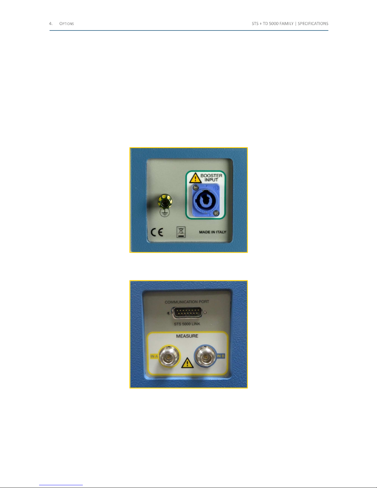
The High Voltage generator TD 5000 performs the measurement of the Tan(δ), of the dissipation factor and of the
capacitance of a transformer or of a bushing, at the frequency of the mains or in a wide frequency range. The
measurement is performed by the module, which is equipped with a patented measurement circuitry; the result is sent
to STS Family.
The measurement circuitry incorporates a reference high voltage capacitor, rated 200 pF, with the following: a variation
better than 0.05%/year, a temperature factor better than and 0.01%,/°, and a Tan(δ) better than 0.005%, and a
reference resistor bridge, with accuracy better than 0.01% and thermal drift less than 1 ppM/°C. The patented circuitry
and the variable frequency output make test results immune from external noise, even in the very highly noisy
environment. The noise it is suppressed using a narrow bandwidth numerical filter. In case of a test frequency equal to
the line frequency, the measurements are automatically performed at different frequencies (F
line
± 4 Hz).
The module has two panels on the sides, and one below: one for the connection to the power supply, the other for the
IN-A (UST-A) and IN-B (UST-B) measurements, and the other for the output connection.
The following image exhibits the power supply on the side:
Figure 30 - Power supply on the side
The following image exhibits the IN-A (UST-A) and IN-B (UST-B) measurements on the side:
Figure 31 - IN-A (UST-A) and IN-B (UST-B) measurements on the side
Shop for Power Metering products online at:
1.877.766.5412
www.PowerMeterStore.c a
Page 66
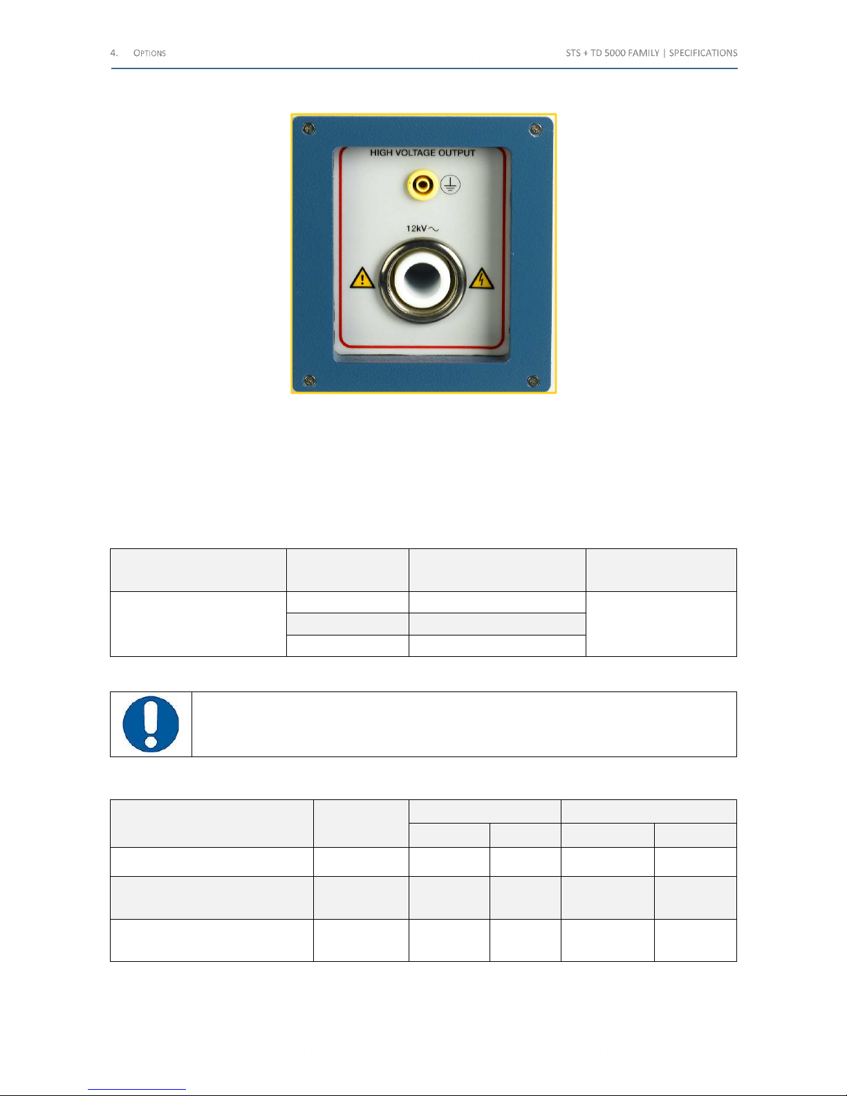
The following image exhibits the HV output on the front panel:
Figure 32 - HV output on the front panel
It is possible to see that there is one HV connector, and there are two metering inputs. This allows the Tan(δ)
measurements of all points with one connection. Besides, the IN-A (UST-A) and IN-B (UST-B) can be used as control
points to avoid the measure of parasitic capacitances.
TD 5000 is powered and controlled by STS. During tests, the high power, not isolated STS voltage output is connected
to TD 5000.
The HV generator has electronic control and the following table lists its main characteristics:
Maximum output voltage
[V]
Output current
[mA]
Maximum output duration
Frequency
[Hz]
12,000
300 >120 s
15÷500 125 > 1 h
100 steady
Table 71 - HV generator main characteristics
ATTENTION: At 10 kV, the output (current value and duration) has the same characteristic
The following table lists the voltage and current output measurement accuracy and resolution:
Internal measure Resolution
Typical accuracy Guaranteed accuracy
± % (rdg) ± % (rg) ± % (rdg) ± % (rg)
12,000 V AC 1 V ± 0.2% ± 0.5 V < 0.3% + 1 V
5 A AC
(@ inputs A or B> 10 mA)
1 mA ± 0.2% ± 1 mA < 0.5% < 0.5%
<10 mA AC
(@ inputs A or B)
0.1 µA ± 0.2% ± 0.1 µA < 0.3% + 0.1 µA
Table 72 - voltage and current output measurement accuracy and resolution
Shop for Power Metering products online at:
1.877.766.5412
www.PowerMeterStore.c a
Page 67
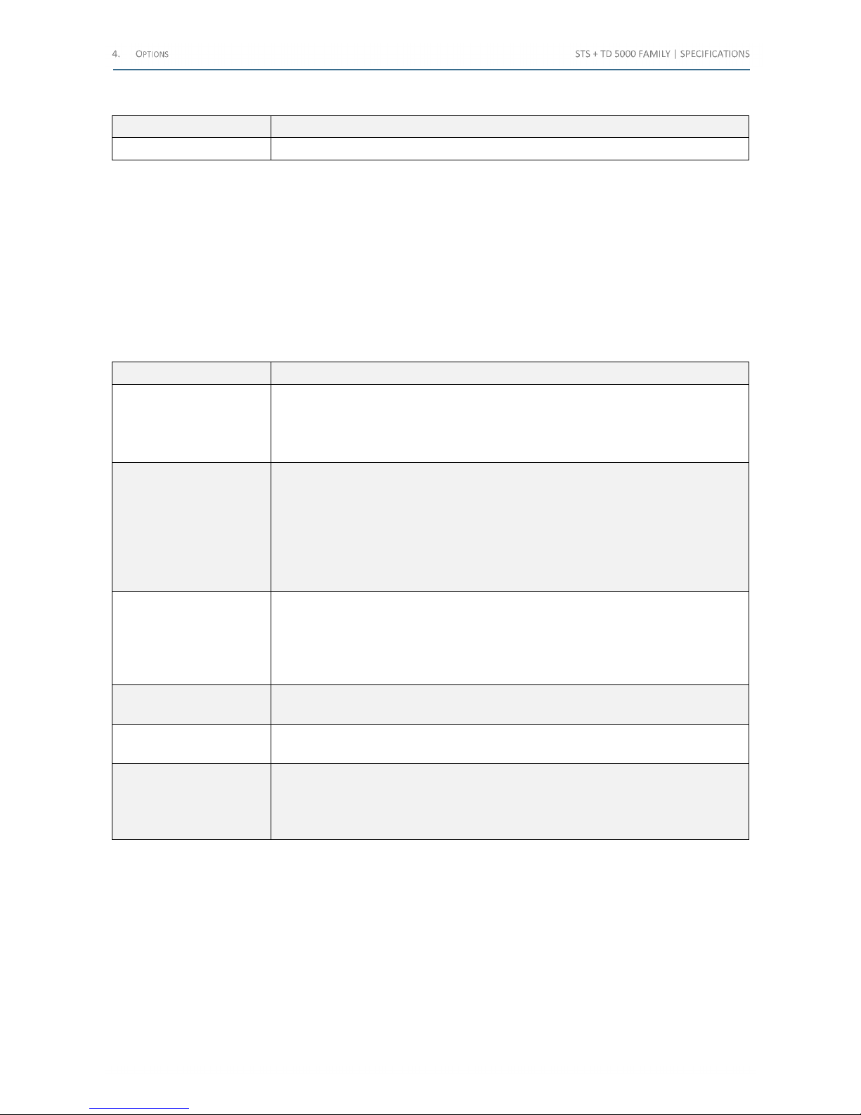
The following table lists the frequency characteristics of TD 5000:
Range Accuracy
15÷500 Hz 50 ppM typical; 100ppM maximum
Table 73 - Frequency characteristics of TD 5000
The connections of the TD 5000 are the following:
• HV panel for the connection of the double shielded safety cable
• TD 5000 Ground socket
• Two measurement sockets (IN A and IN B)
The available test selections are the following:
• Ungrounded: UST-A; UST-B; UST A+B
• Grounded: GST; GSTg-A; GSTg-B; GSTg-A+B
The following table lists the derived measurements from the measurements of V and I:
Measurement Characteristics
Capacitance
Measurement range 1, from 1 pF to 3uF. Resolution: 6 digits. Accuracy, typical: ±0.03%
of the value ±0.1 pF; guaranteed: < 0.1% of the value +1pF ((from 45 to 70 Hz)
Measurement range 2, from 10 nF to 3 uF Resolution: 6 digits. Accuracy, typical: ±0.1%
of the value ±10 pF; guaranteed: < 0,2% of the value +10 pF
Tan(δ)
(dissipation factor DF)
• Measurement range 1: from 0 to 10% (capacitive). Resolution: 5 digits; accuracy,
typical: 0.05% of the value ±0.005 %; guaranteed: 0.1% of the value ±0.005 % (from
45 to 70 Hz, current < 10 mA)
• Measurement range 2: from 0 to 100%. Resolution: 5 digits; accuracy, typical: 0.3%
of the value ±0.01 %; guaranteed: 0.5% of the value ±0.02 %
• Measurement range 3: over 100%. Resolution: 5 digits; accuracy, typical: 0.5% of
the value ±0.03 %; guaranteed: 0.8% of the value ±0.05 %
Power factor PF
(cos(φ))
• Measurement range 1: from 0 to 10% (capacitive). Resolution: 5 digits; accuracy,
typical: 0.05% of the value ±0.005 %; guaranteed: 0.1% of the value ±0.005 % (from
45 to 70 Hz, current < 10 mA)
• Measurement range 2: from 0 to 100%. Resolution: 5 digits; accuracy, typical: 0.3%
of the value ±0.02 %; guaranteed: 0.5% of the value ±0.02 %
Impedance
From 1 kOhm to 1,400 MΩ. Accuracy, typical 0.3% of the value ±0.1%, guaranteed
<0.5% of the value. Resolution: 6 digits
Power
Measurement ranges: 10 kW, 100 kW, 1 MW. Resolution (5 digits): 0.1 mW; accuracy:
<0.5% of the value ±1 mW
Inductance
• Measurement range 1: from 1 H to 10 kH. Resolution (5 digits): 0.1 mH; accuracy,
typical: 0.3% of the value ±0.5 mH; guaranteed: 0.5% of the value
• Measurement range 2: from 100 H to 1 MH. Resolution (5 digits): 1 H; accuracy,
typical: 0.3% of the value; guaranteed: <0.5% of the value
Table 74 - Derived measurements from the measurements of V and I
The same ranges and accuracies are applied to reactive and apparent power measurements.
Other characteristics:
• Dimensions: 440 (W) X 345 (H) X 210 (D) mm
• Weight: 25 kg
Shop for Power Metering products online at:
1.877.766.5412
www.PowerMeterStore.c a
Page 68
The following table lists the connection cables supplied with TD 5000 (they come as standard with the test set; however,
they can also be ordered separately):
Cable Characteristics
No 1 yellow-green
connection cable
6 m long, for the ground connections. Terminated with terminator on one side, and
with a clamp on the other side
No 2 yellow-green
connection cables
1 m long, for the ground connections. Terminated with terminators
No 1yellow-green
connection cable
2 m long, for the ground connections. Terminated with terminators
No 1 power cable To the BOOSTERS connector of STS, 1 m long
No 1 power cable To the BOOSTERS connector of STS, 2 m long
No 1 High voltage
connection cable
20 m long, 25 kV, with earth screen, for the connection to the device under test.
Terminated on the device side with an isolated banana plug, and on the TD 5000 side
with two plugs: one for the HV and the other one for the ground
No 1 clamp 25 mm opening, with a connector which mates with the HV cable with 6 mm plug
No 1 bigger clamp 60 mm min. opening, with a connector which mates with the HV cable with 6 mm plug
No 2 Shielded connection
cables
20 m long, for the connection to the metering points. Terminated on the TD 5000 side
with the metering connector, and on the device side with a 4 mm banana plug. Cables
are mounted on wheels
No 2 clamps
25 mm opening, terminated with 4 mm sockets, which allow connecting to the metering
point
No 2 Kelvin type clamps
60 mm opening, terminated with 4 mm sockets, which allow connecting to the metering
point
No 1 signals connection
cable
To the EXT. DEVICES connector of STS, 1 m long
No 1 signals connection
cable
To the EXT. DEVICES connector of STS, 2 m long
No 1 Transport Case
Table 75 - Cables supplied with TD 5000
Shop for Power Metering products online at:
1.877.766.5412
www.PowerMeterStore.c a
Page 69
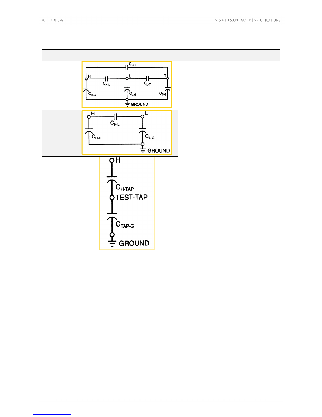
The following table lists the parasitic capacitances which exist in a three winding (two secondary) power transformer,
in a two winding (one secondary) power transformer and in a bushing transformer:
Transformer Scheme Terms
Three winding
(two
secondary)
power
transformer
• H = high voltage terminal
• L = low voltage terminal
• T = third winding
• G = Ground
• C(H-T): parasitic capacitance between High
voltage and T
• C(H-L): parasitic capacitance between High
voltage and Low voltage
• C(H-G): parasitic capacitance between High
voltage and Ground
• C(L-G): parasitic capacitance between Low
voltage and Ground
• C(L-T): parasitic capacitance between Low
voltage and T
• C(T-G): parasitic capacitance between T and
Ground
• C(H-Tap): parasitic capacitance between
High voltage and Tap
• C(Tap-G): parasitic capacitance between Tap
and Ground
• Test tap = test terminal
Two winding
(one
secondary)
power
transformer
Bushing
transformer
Table 76 - Parasitic capacitances
Shop for Power Metering products online at:
1.877.766.5412
www.PowerMeterStore.c a
Page 70
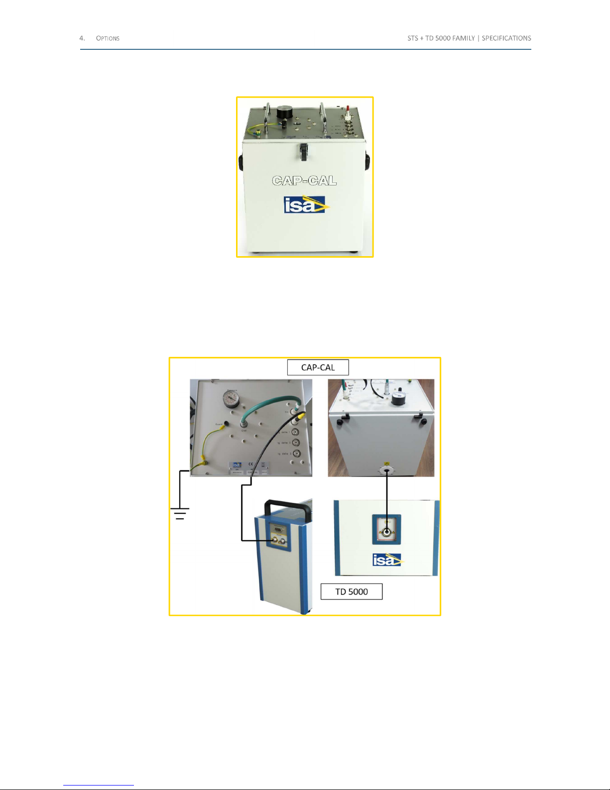
4.20 CAP-CAL reference capacitor (code PII40175)
The following image exhibits the CAP-CAL reference capacitor:
Figure 33 - CAP-CAL reference capacitor
Purpose of the reference capacitor is to check the actual calibration of TD 5000 for the measures of the capacitance and
Tan(δ).
The CAP-CAL includes an extremely high accuracy high voltage and low Tan(δ) capacitor. The device includes also 4
resistances to be connected to the capacitor in series mode, to generate some known Tan(δ) values.
The following image exhibits the connection of the CAP-CAL to the TD 5000:
Figure 34 - Connection of the CAP-CAL to the TD 5000
A calibration certificate is issued by ISA laboratory and it is supplied together the CAP-CAL.
Shop for Power Metering products online at:
1.877.766.5412
www.PowerMeterStore.c a
Page 71
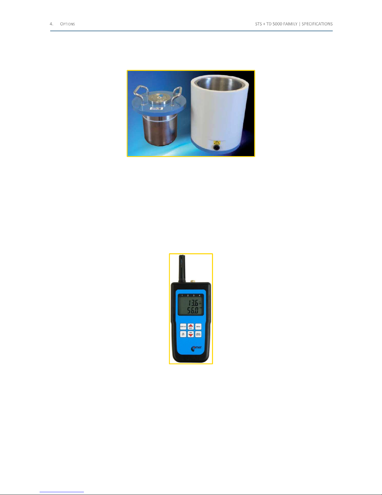
4.21 STOIL cell for the insulating oil check (code PII13175)
This option applies to TD 5000, to perform Tan(δ) test of the PT oil.
The following image exhibits the STOIL option:
Figure 35 - STOIL option
Cell characteristics are the followings.
• Maximum test voltage: 12 kV
• Cell volume: 1 l
• Empty cell capacity: (60±10) pF
The option comes complete with the following connection cables: No. 2 HV connection cables, 2 m long, terminated on
the TD 5000 side with the HV connector, and on the other side with the proper termination for the cell.
4.22 Digital Thermo Hygrometer (code PII44175)
The following image exhibits the Digital Thermo Hygrometer:
Figure 36 - Digital Thermo Hygrometer
Some tests performed by STS, such as Tan(δ), are influenced by temperature and humidity. The option allows measuring
these parameters, and to input them into the test settings.
Shop for Power Metering products online at:
1.877.766.5412
www.PowerMeterStore.c a
Page 72
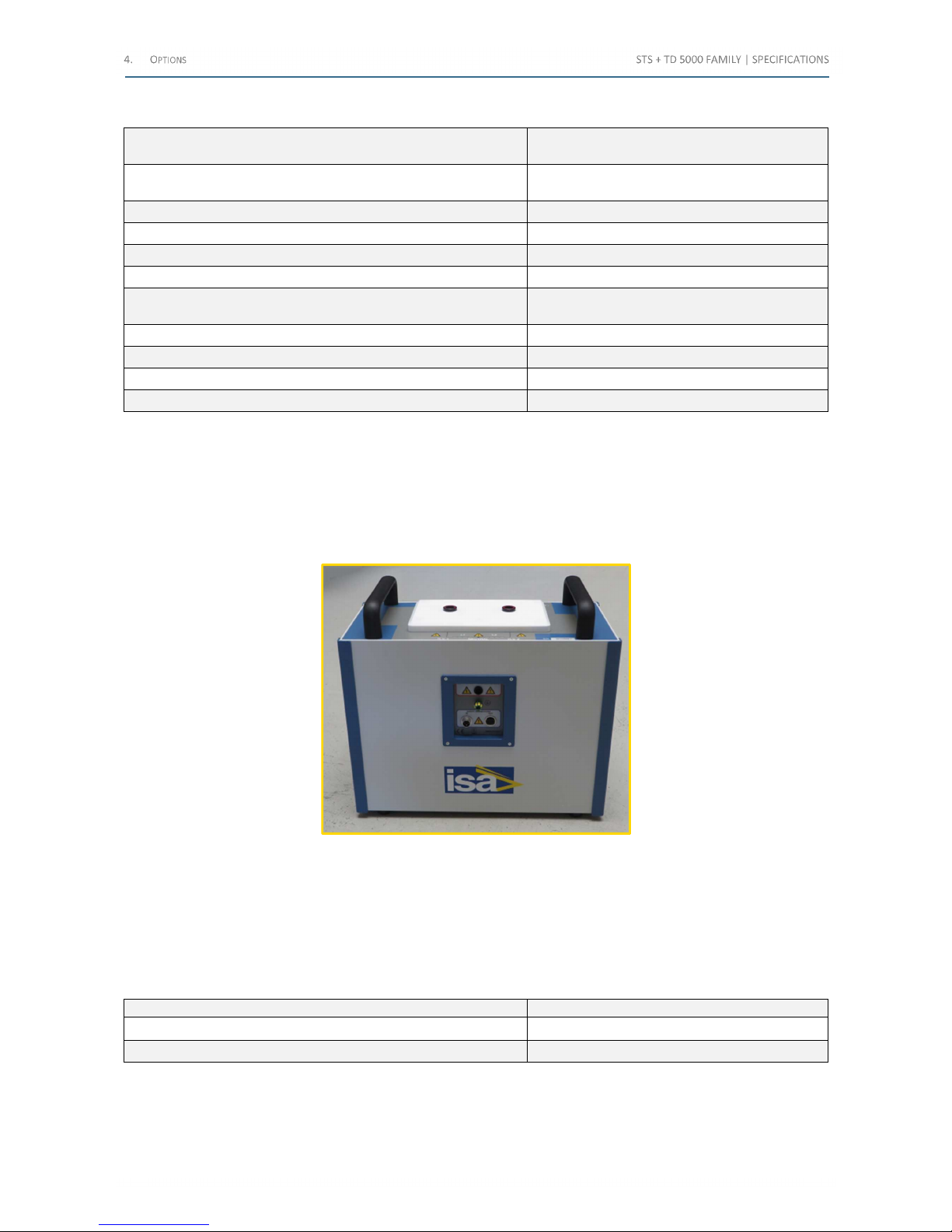
The following table lists the main characteristics:
Characteristic Value
Temperature range
(-10÷+60) °C
(-50÷+250) °C with an external sensor
External temperature sensor RTD Ni1000/6180 ppM, not included
Temperature measurement accuracy ±0.4 °C
Humidity measurement range (5÷95)% RH
Resolution of humidity measurement 0.1%
Accuracy of humidity measurement
±2.5% RH
over the whole range
Battery 9 V
Battery life Typically 9 months
Dimensions (141x71x27) mm
Weight 150 g
Table 77 - Digital Thermo Hygrometer main characteristics
4.23 RCTD reactor for motors and generators measures (Code PII47175)
This option applies to TD 5000 and allows increasing the test current and getting the maximum test voltage on high
capacitive burdens.
The following image exhibits the RCTD option:
Figure 37 - RCTD option
Each RCTD is composed by two inductors with a nominal value of 40 H and a steady current of 0.6 A.
The maximum current on each inductor can be up to 1 A for more a limited time.
The inductors can be connected in parallel on the load in order to increase the test frequency.
It is possible to connect two RCTD in parallel in order to have three or four inductors connected in parallel.
The following table lists the RCTD characteristics:
Characteristic Value
Weight
39 kg
Dimensions 23 x 44 x 28 mm
Table 78 – RCTD characteristics
Shop for Power Metering products online at:
1.877.766.5412
www.PowerMeterStore.c a
Page 73
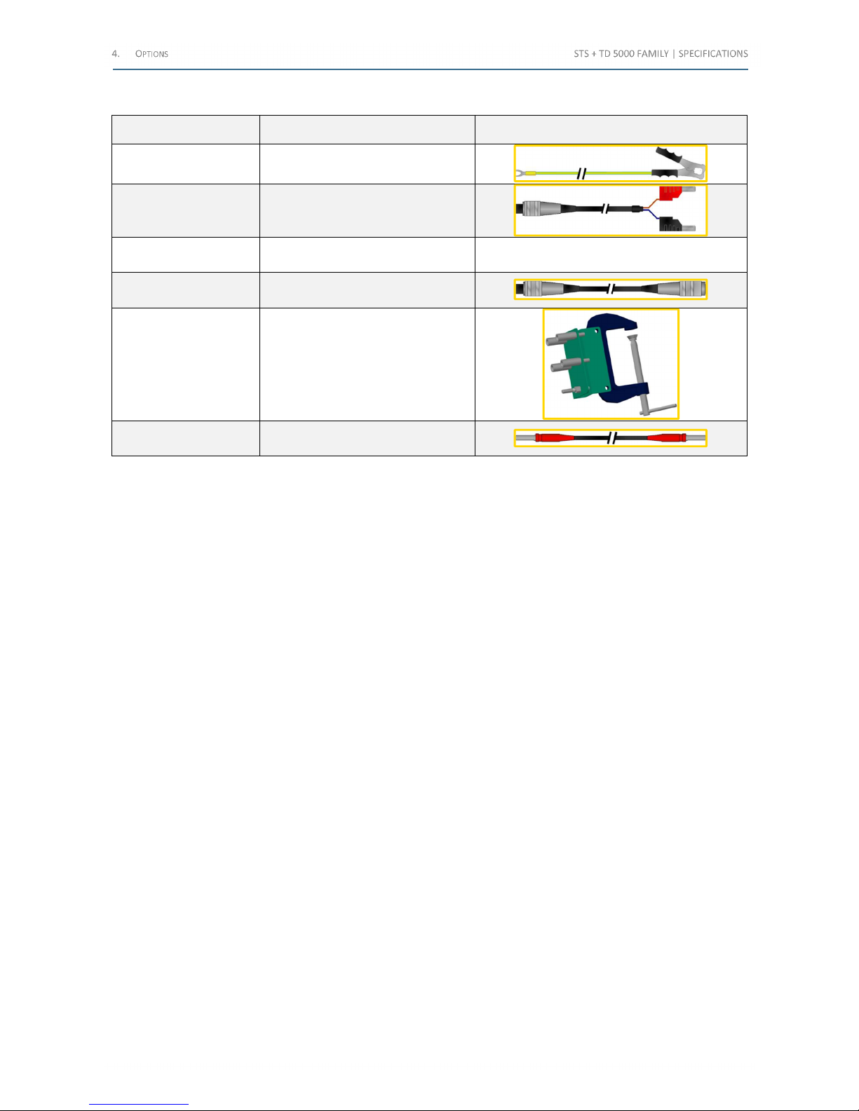
The reactor has a standard cable kit (code PII48175) and the following table lists them:
Cable Characteristics Scheme
N. 1 ground cable
6 m long, 6 mm2 terminated with
terminator and clamp
N. 1 safety cable To STS; 10 m long, 2x0,5 mm2
N. 1 “Safety IN”
connector
For the safety loop closure
N. 1 Safety cable
To connect another RCTD; 2 m long,
2x0,5 mm2
N. 1 clamp
Screw terminal, with plate for the HV
connection
N. 2 HV cables
5 m long, not shielded, terminated
with 6 mm male connectors
Table 79 – RCTD cables
Shop for Power Metering products online at:
1.877.766.5412
www.PowerMeterStore.c a
Page 74

5 P
ROTECTIONS
The protections of the STS are the following:
• If the test set is not connected to the ground, the test set does not allow for power generation, and warns the
operator with a diagnostic message and a fixed led light
• Fuse on the mains supply
• Fuse on the low power current and voltage outputs
• Fuse on the current meter input
• At power-on, a diagnostic sequence controls
• Key microprocessor board components
• Auxiliary supply voltages.
If something is wrong, the operator is alerted by a message.
• Emergency pushbutton: if pressed, all main outputs are removed
• The high voltage output has the following protections
• Confirmation key: if not turned, the HV output is not generated
• The HV is generated only if selected; the HV selection is confirmed by warning lights
• Thermal sensor on the main transformer. In case of over-temperature, an alarm message is displayed
• Thermal sensor on the active electronic devices. In case of over-temperature, an alarm message is displayed
• If maximum current limits and time duration of power transformer generators are trespassed, the generation
is interrupted, and the operator is warned by an alarm message
• The current measurement input is protected against wrong connections
Shop for Power Metering products online at:
1.877.766.5412
www.PowerMeterStore.c a
Page 75
R
EVISIONS
The following table lists the revisions of the document:
No. Date Description
1 January 2011 First issue
2 October 2011 Modified HV outputs, tanδ, low voltage, STCS
3 February 2012
Revised all options
Added the oil test cell
4 January 2013 Final revision
5 April 2013 Improved the description of TD 5000
6 February 2014 Added the PLCK and the RCTD options
7 June 2014 Improved description of RCTD
8 July 2014 Added STCS Booster 20 A Winding Resistance Module option
9 October 2014 Added STSA images and STSA3V option
10 December 2014
Added STLG ground grid testing module
Added STSG safety grounding module
Revised
11 January 2015 Added the STDE demagnetizer option
12 February 2015
Added BUX2000 option
Added IEC61850-9-2LE function description
Added long cables kit PII57175
Trigger options revised
13 July 2015
TD5000 option revised
STOIL option revised
14 October 2015 Complete layout revision
Table 80 - Revisions
Shop for Power Metering products online at:
1.877.766.5412
www.PowerMeterStore.c a
Page 76

L
IST OF FIGURES
F
IGURE 1 -
STS 5000 ............................................................................................................................................................ 12
F
IGURE 2 - TEST SET FRONT PANEL
............................................................................................................................................ 13
F
IGURE 3 – LEFT PANEL COMPONENTS
....................................................................................................................................... 15
F
IGURE 4 - RIGHT PANEL COMPONENTS
...................................................................................................................................... 16
F
IGURE 5 -
STS
DISPLAY
.......................................................................................................................................................... 29
F
IGURE 6 – HOME PAGE
......................................................................................................................................................... 30
F
IGURE 7 – “CURRENT TRANSFORMERS" ICON
............................................................................................................................ 30
F
IGURE 8 - "CURRENT TRANSFORMERS/HEADER AND NOMINAL VALUES" PAGE (TAB DESCRIPTION
) ..................................................... 31
F
IGURE 9 - "CURRENT TRANSFORMERS/HEADER AND NOMINAL VALUES" PAGE (TAB NOMINALS
) ........................................................ 31
F
IGURE 10 - "CURRENT TRANSFORMERS/HEADER AND NOMINAL VALUES" PAGE (TAB TOLERANCES
) .................................................... 32
F
IGURE 11 - "CURRENT TRANSFORMERS" TEST PAGE (CONVENTIONAL TYPE
) .................................................................................... 32
F
IGURE 12 -
"CTS – R
ATIO POLARITY AND BURDEN CURRENT METHOD" PAGE
................................................................................. 33
F
IGURE 13 - TRANSIT CASE
...................................................................................................................................................... 49
F
IGURE 14 - REMOTE SAFETY SWITCH
....................................................................................................................................... 51
F
IGURE 15 - WARNING STROBE LIGHT
....................................................................................................................................... 51
F
IGURE 16 - SAFETY WARNINGS
(28)
CONNECTOR
...................................................................................................................... 51
F
IGURE 17 -
STCS
OPTION
...................................................................................................................................................... 52
F
IGURE 18 -
STCS B
OOSTER 20 A DC OPTION
............................................................................................................................ 53
F
IGURE 19 -
STDE
OPTION
...................................................................................................................................................... 54
F
IGURE 20 -
STSA S
URGE ARRESTER
......................................................................................................................................... 55
F
IGURE 21 -
BUX 3000
OPTION
.............................................................................................................................................. 55
F
IGURE 22 - CURRENT CLAMP
.................................................................................................................................................. 57
F
IGURE 23 -
PLCK
OPTION
...................................................................................................................................................... 58
F
IGURE 24 -
STLG
OPTION
...................................................................................................................................................... 58
F
IGURE 25 -
STSG
OPTION
...................................................................................................................................................... 62
F
IGURE 26 - GROUND GRID TEST ACCESSORIES KIT
...................................................................................................................... 64
F
IGURE 27 – CURRENT CLAMP METER
...................................................................................................................................... 65
F
IGURE 28 - FOLDABLE TROLLEY
............................................................................................................................................... 66
F
IGURE 29 - TD
5000 ............................................................................................................................................................ 66
F
IGURE 30 - POWER SUPPLY ON THE SIDE
................................................................................................................................... 67
F
IGURE 31 -
IN-A (UST-A)
AND
IN-B (UST-B)
MEASUREMENTS ON THE SIDE
.................................................................................. 67
F
IGURE 32 - HV OUTPUT ON THE FRONT PANEL
........................................................................................................................... 68
F
IGURE 33 -
CAP-CAL
REFERENCE CAPACITOR
............................................................................................................................ 72
F
IGURE 34 - CONNECTION OF THE
CAP-CAL
TO THE TD
5000 ...................................................................................................... 72
F
IGURE 35 -
STOIL
OPTION
..................................................................................................................................................... 73
F
IGURE 36 - DIGITAL THERMO HYGROMETER
.............................................................................................................................. 73
F
IGURE 37 -
RCTD
OPTION
..................................................................................................................................................... 74
Shop for Power Metering products online at:
1.877.766.5412
www.PowerMeterStore.c a
Page 77

L
IST OF TABLES
T
ABLE 1 -
STS F
AMILY MODELS
.................................................................................................................................................. 7
T
ABLE 2 - DIFFERENCES AMONG THE
STS F
AMILY MODELS
.............................................................................................................. 7
T
ABLE 3 - CURRENT TRANSFORMER TESTS
.................................................................................................................................... 7
T
ABLE 4 - VOLTAGE TRANSFORMERS TESTS
................................................................................................................................... 8
T
ABLE 5 – POWER TRANSFORMERS TESTS
..................................................................................................................................... 8
T
ABLE 6 - CIRCUIT BREAKERS TESTS
............................................................................................................................................. 8
T
ABLE 7 – RESISTANCES TESTS
.................................................................................................................................................... 8
T
ABLE 8 - OPTIONAL MODULES
................................................................................................................................................. 10
T
ABLE 9 - FRONTAL PANEL COMPONENTS
(1/2) .......................................................................................................................... 13
T
ABLE 10 – FRONTAL PANEL COMPONENTS
(2/2) ........................................................................................................................ 14
T
ABLE 11 – LEFT PANEL COMPONENTS
....................................................................................................................................... 15
T
ABLE 12 – RIGHT PANEL COMPONENTS
.................................................................................................................................... 16
T
ABLE 13 – STANDARDS RELATED TO THE
EMC D
IRECTIVE
(2/2) ................................................................................................... 17
T
ABLE 14 - STANDARDS RELATED TO THE LV DIRECTIVE
................................................................................................................ 18
T
ABLE 15 - HIGH AC CURRENT: OUTPUT CHARACTERISTICS
(1/2) ................................................................................................... 20
T
ABLE 16 - HIGH AC CURRENT: OUTPUT CHARACTERISTICS
(2/2) ................................................................................................... 20
T
ABLE 17 - HIGH DC CURRENT: OUTPUT CHARACTERISTICS
(1/2) ................................................................................................... 20
T
ABLE 18 - HIGH DC CURRENT: OUTPUT CHARACTERISTICS
(2/2) ................................................................................................... 20
T
ABLE 19 – LOW AC CURRENT: OUTPUT CHARACTERISTICS
............................................................................................................ 21
T
ABLE 20 – LOW DC CURRENT: OUTPUT CHARACTERISTICS
............................................................................................................ 21
T
ABLE 21 - HIGH AC VOLTAGE: OUTPUT CHARACTERISTICS
(1/4) .................................................................................................... 22
T
ABLE 22 - HIGH AC VOLTAGE: OUTPUT CHARACTERISTICS
(2/4) .................................................................................................... 22
T
ABLE 23 - HIGH AC VOLTAGE: OUTPUT CHARACTERISTICS
(3/4) .................................................................................................... 22
T
ABLE 24 – HIGH AC VOLTAGE: OUTPUT CHARACTERISTICS
(4/4) ................................................................................................... 23
T
ABLE 25 - HIGH AC VOLTAGE: CURRENT RANGES AND ASSOCIATED ERRORS
..................................................................................... 23
T
ABLE 26 – HIGH AC VOLTAGE: PHASE SHIFT METERING CHARACTERISTICS
....................................................................................... 23
T
ABLE 27 – LOW AC CURRENT: OUTPUT CHARACTERISTICS
............................................................................................................ 23
T
ABLE 28 – HIGH POWER OUTPUT: OUTPUT CHARACTERISTICS
....................................................................................................... 24
T
ABLE 29 – FREQUENCY RANGE ON ALL THE AC OUTPUTS
............................................................................................................. 24
T
ABLE 30 – OTHER FEATURES OF MAIN OUTPUTS
......................................................................................................................... 24
T
ABLE 31 – OUTPUTS MEASUREMENT
....................................................................................................................................... 25
T
ABLE 32 - RESOLUTION AND ACCURACY
.................................................................................................................................... 25
T
ABLE 33 - PHASE ANGLE RESOLUTION AND ACCURACY
................................................................................................................. 26
T
ABLE 34 - AVAILABLE MEASUREMENTS
..................................................................................................................................... 27
T
ABLE 35 - PARAMETERS FOR
CT, VT
AND PT RATIO MEASUREMENT
.............................................................................................. 27
T
ABLE 36 - PARAMETERS FOR THE BURDEN TEST
.......................................................................................................................... 27
T
ABLE 37 - RESISTANCE TEST: RANGE AND ACCURACY
................................................................................................................... 28
T
ABLE 38 - IMPEDANCE TEST: RANGE AND ACCURACY
................................................................................................................... 28
T
ABLE 39 - PHASE ANGLE RESOLUTION AND ACCURACY
................................................................................................................. 28
T
ABLE 40 - MAIN FEATURES OF THE DISPLAY
............................................................................................................................... 29
T
ABLE 41 - CURRENT TRANSFORMERS TESTS
(1/4) ...................................................................................................................... 34
T
ABLE 42 - CURRENT TRANSFORMERS TESTS
(2/4) ...................................................................................................................... 35
T
ABLE 43 - CURRENT TRANSFORMERS TESTS
(3/4) ...................................................................................................................... 36
T
ABLE 44 - CURRENT TRANSFORMERS TESTS
(4/4) ...................................................................................................................... 37
T
ABLE 45 - VOLTAGE TRANSFORMERS TESTS
(1/2) ...................................................................................................................... 38
T
ABLE 46 - VOLTAGE TRANSFORMERS TESTS
(2/2) ...................................................................................................................... 39
T
ABLE 47 - POWER TRANSFORMERS TESTS
(1/3) ......................................................................................................................... 40
T
ABLE 48 – POWER TRANSFORMERS TESTS
(2/3) ........................................................................................................................ 41
T
ABLE 49 – POWER TRANSFORMERS TESTS
(3/3) ........................................................................................................................ 42
T
ABLE 50 - CIRCUIT BREAKERS TESTS
......................................................................................................................................... 43
T
ABLE 51 - RESISTANCES TESTS
(1/2) ........................................................................................................................................ 44
T
ABLE 52 – RESISTANCES TESTS
(2/2) ....................................................................................................................................... 45
Shop for Power Metering products online at:
1.877.766.5412
www.PowerMeterStore.c a
Page 78

TABLE 53 – OTHER POSSIBLE TESTS ........................................................................................................................................... 46
TABLE 54 - CABLES PROVIDED WITH THE UNIT ............................................................................................................................. 47
TABLE 55 - OTHER CHARACTERISTICS OF THE STS ........................................................................................................................ 48
TABLE 56 – TRANSIT CASE MAIN CHARACTERISTICS ....................................................................................................................... 49
TABLE 57 - TRANSPORT CASES CODING ...................................................................................................................................... 49
TABLE 58 – STCS CABLES ....................................................................................................................................................... 52
TABLE 59 – STDE MAIN CHARACTERISTICS ................................................................................................................................. 54
TABLE 60 - MAX TEST CURRENTS AND DURATIONS (230 V) FOR BUX 3000 ..................................................................................... 56
TABLE 61 - MAX TEST CURRENTS AND DURATIONS (110 V) FOR BUX 3000 ..................................................................................... 56
TABLE 62 - MAX TEST CURRENTS AND DURATIONS (230 V) FOR BUX 2000 ..................................................................................... 56
TABLE 63 - MAX TEST CURRENTS AND DURATIONS (110 V) FOR BUX 2000 ..................................................................................... 57
TABLE 64 - CURRENT CLAMP MAIN CHARACTERISTICS ................................................................................................................... 57
TABLE 65 – KIT ELEMENTS (1/2) .............................................................................................................................................. 60
TABLE 66 – KIT ELEMENTS (2/2) .............................................................................................................................................. 61
TABLE 67 - STUDS CHARACTERISTICS ......................................................................................................................................... 63
TABLE 68 - ELEMENTS OF THE GROUND GRID TEST ACCESSORIES KIT ............................................................................................... 64
TABLE 69 - CURRENT CLAMP METER MAIN CHARACTERISTICS......................................................................................................... 65
TABLE 70 - TROLLEY CHARACTERISTICS ....................................................................................................................................... 66
TABLE 71 - HV GENERATOR MAIN CHARACTERISTICS ..................................................................................................................... 68
TABLE 72 - VOLTAGE AND CURRENT OUTPUT MEASUREMENT ACCURACY AND RESOLUTION ................................................................... 68
TABLE 73 - FREQUENCY CHARACTERISTICS OF TD 5000 ................................................................................................................ 69
TABLE 74 - DERIVED MEASUREMENTS FROM THE MEASUREMENTS OF V AND I ................................................................................... 69
TABLE 75 - CABLES SUPPLIED WITH TD 5000 ............................................................................................................................. 70
TABLE 76 - PARASITIC CAPACITANCES ........................................................................................................................................ 71
TABLE 77 - DIGITAL THERMO HYGROMETER MAIN CHARACTERISTICS ............................................................................................... 74
TABLE 78 – RCTD CHARACTERISTICS ......................................................................................................................................... 74
TABLE 79 – RCTD CABLES....................................................................................................................................................... 75
TABLE 80 - REVISIONS ............................................................................................................................................................ 77
Shop for Power Metering products online at:
1.877.766.5412
www.PowerMeterStore.c a
 Loading...