

ISA Kelly P100 TF RV Praline 110 A, Kelly P100 VN Pane 164, Kelly P100 TF RV Praline 164 A, Kelly P100 TF RV Praline 218 A, Kelly P100 VN Pizza 164 User guide

KELLY
IT EN
ISA S.r.l.
06083 Bastia Umbra - Perugia - Italy
Tel. +39 075 80171 - Fax +39 075 8000900
USE AND MAINTENANCE MANUAL
Via del Lavoro, 5
www.isaitaly.com
KELLY
428000587
037
1
1. MANUFACTURER 4
2. WARRANTY TERMS AND CONDITIONS 4
3. EQUIPMENT IDENTIFICATION 5
4. USE 6
4.1 COMPOSITION 6
5. NOTES / IMPORTANT NOTES 7
6. SAFETY 9
6.1 SAFETY DEVICES PRESENT 9
6.2 FIXED PROTECTIONS 9
6.3 ISOLATING THE ELECTRIC POWER SUPPLY 9
6.4 RESIDUAL RISKS 9
6.5 RISKS OF CONTACT WITH LIVE PARTS 9
6.6 FIRE 10
6.7 EXPLOSIVE ATMOSPHERE 10
6.8 SLIPPING 10
6.9 TRIPPING 10
6.10 CIRCUIT FAULTS 10
6.11 WARNING SIGNS (if any) 10
6.12 RISKS OF EXPLOSION 10
6.13 REFRIGERANTS (where applicable) 11
7. DISPOSAL OF WASTE MATERIAL 12
8. INSTALLATION 13
8.1 STORAGE AND UNPACKING 13
8.2 INSTALLATION - POSITIONING - ENVIRONMENTAL CONDITIONS 13
8.3 ELECTRIC CONNECTION 13
9. MAINTENANCE 14
10. FAULTS - TECHNICAL AFTER-SALES ASSISTANCE 15
10.1 ALARMS LIST (where present) 16
11. TECHNICAL SPECIFICATIONS 17
11.1 POSITIONING / LEVELING 32
11.2 LOAD LIMITS 32
12. CONTROL PANEL 33
13. CLEANING 34
14. PROLONGED APPLIANCE SWITCH-OFF 36
KELLY
USE AND MAINTENANCE MANUAL
428000587
037
2
IT
EN
Attachment 1 DECLARATION OF CONFORMITY 37
Attachment 2 WIRING DIAGRAM - 412100329000 38
Attachment 3 WIRING DIAGRAM - 412100353000 39
Attachment 4 WIRING DIAGRAM - 412100355000 40
Attachment 5 WIRING DIAGRAM - 412100362000 41
Attachment 6 WIRING DIAGRAM - 412136572100 42
Attachment 7 WIRING DIAGRAM - 412136574100 43
Attachment 8 WIRING DIAGRAM - 412138611300 44
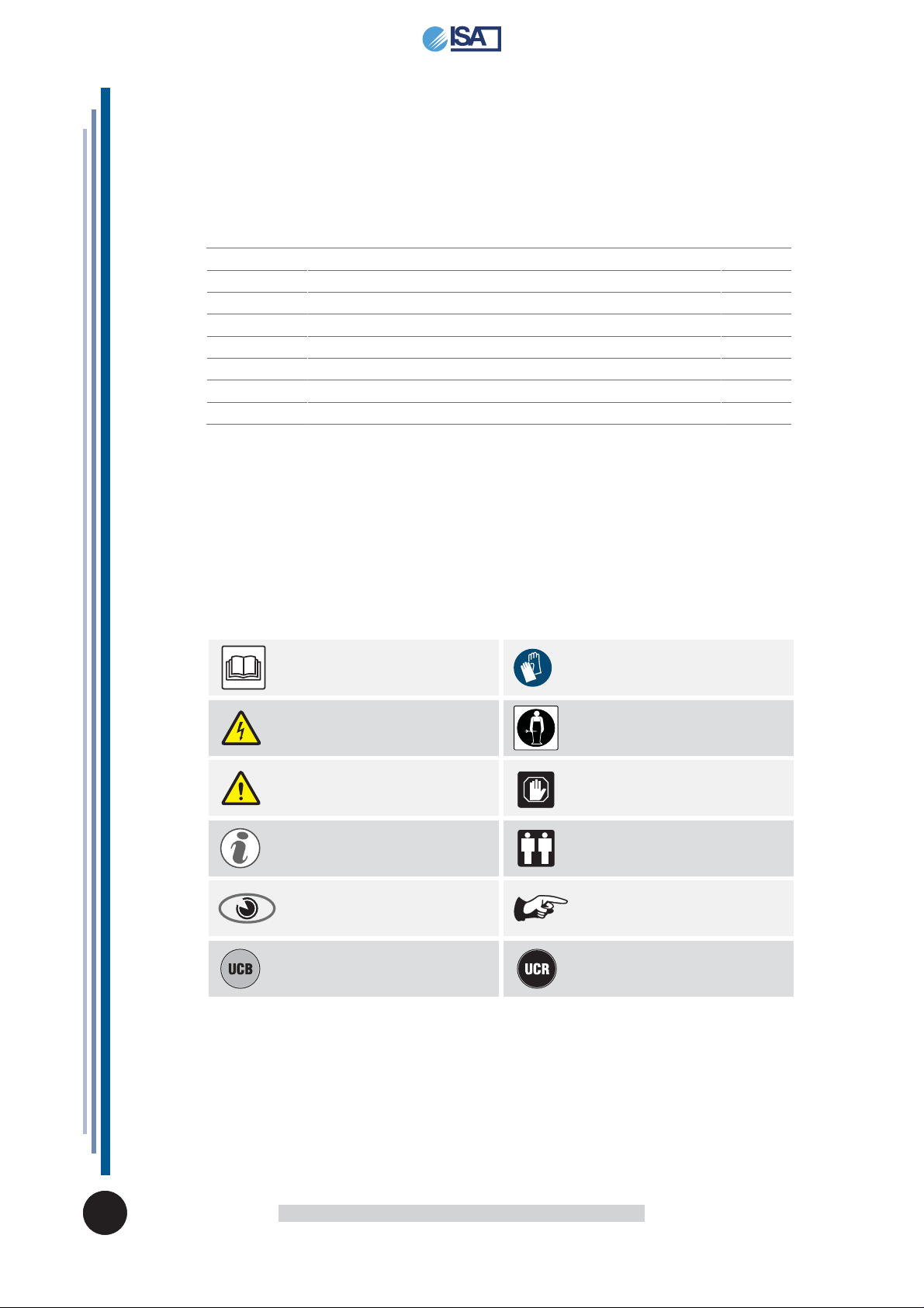
The manual contains symbols to attract the reader’s attention and highlight particularly
important aspects. The table below illustrates the meaning of the various symbols used.
Read the instructions manual
Danger: Live electrical parts
Attention / Danger
Information
Visual observation
Condensing unit on board
Use of protective clothing
Requests for maintenance or operations must
be carried out by qualifi ed staff or technical
after-sales centres.
Important information
Operations that must be performed by two
persons.
Notes / Important notes
Remote condensing unit
IT EN
KELLY
USE AND MAINTENANCE MANUAL
428000587
037
3

1. MANUFACTURER
ISA S.r.l.
Via del Lavoro, 5
06083 - Bastia Umbra - Perugia - Italy
Tel. +39 075 80171
Fax +39 075 8000900
www.isaitaly.com
2. WARRANTY TERMS AND CONDITIONS
The seller's warranty on the equipment is valid for 12 (TWELVE) months from the date of delivery.
The warranty includes repairs or replacements of any faulty parts due to manufacturing processes or
installation after written communication has been received, stating the appliance serial number and date
of installation.
Not included in the warranty:
• all defects caused by incorrect use of the appliance
• all defects caused by incorrect electrical connection
• all defects caused by normal wear (for instance compressor failure and fl uorescent lamp malfunctioning
that is not due to manufacturing defects)
• calls for installation, technical instructions, adjustments and cleaning the condenser
If the seller's technical staff detect any tampering, unauthorised repairs or inappropriate use of appliance
the warranty will be invalidated.
Shipment of components covered by the warranty is freight collect only.
Any damage to the appliance detected at the time of delivery due to transport must be reported on the
same shipping note to claim compensation from the carrier.
The seller cannot be held liable in the event of damage to the preserved product due to appliance failure
KELLY
USE AND MAINTENANCE MANUAL
428000587
037
4
IT
EN
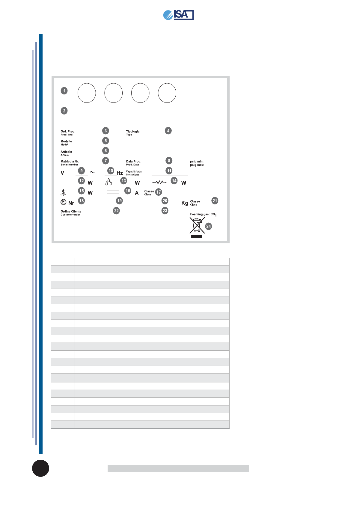
3. EQUIPMENT IDENTIFICATION
• Find the label affi xed on the machine to read the technical data.
• Check the machine model and the power supply voltage before you perform any operation.
• If you uncover mismatches, contact the manufacturer or the company that supplied the machine
immediately.
1 Symbols of Compliance
2 Manufacturer's address
3 Production Order
4 Type
5 Model Name
6 Article
7 Serial Number
8 Production Date
9 - 10 Power supply Voltage and Frequency
11 Gross Capacity
12 Absorption at Rated Capacity
13 Absorption during Defrosting
14 Absorption of Heating Elements
15 Lamp Power
16 Fuse Value
17 Climate Class
18 Number of Motors
19 Type of Coolant
20 Amount of Coolant
21 Safety Class
22 - 23 Customer order
24 WEEE Mark
IT EN
KELLY
USE AND MAINTENANCE MANUAL
428000587
037
5
4. USE
This appliance is exclusively intended to:
• Dry heated (Bain-Marie Hot display cabinet: Exposure of pre-cooked food
• Pastry display cabinets: Exhibition and sale of confectionery, fresh, dried or
snack
• Ice cream display cabintes: Exhibition and sale of ice cream
• Display cabinets (Bread / Pizza): Exhibition and sale of bread or pizza
The manufacturer is not liable for injury to persons or damage to property or the appliance itself
caused by the displaying of products other than those described above.
Never use electric devices inside this appliance. Do not use mechanical or other means to accelerate
the defrosting process, other than recommended by the manufacturer. Keep the air vents in the casing
of the appliance or in the structure built into the wall free of obstructions.
THE APPLIANCE IS INTENDED FOR PROFESSIONAL USE.
Uses not allowed
• Food preservation.
• Displaying and/or preserving non-food products (chemicals, pharmaceuticals, etc...).
4.1 COMPOSITION
The appliance is made up from a unique cabinet, onto which all devices necessary to make it a professional
and effi cient product for its declared use, are installed.
The appliance is made up from:
• Refrigeration system (refrigeration equipment)
• Condensing unit on board (UCB) PR remore (UCR)
• Electric plant
• Electronic control panel
• Insulated monolithic structure in ecological polyurethane
KELLY
USE AND MAINTENANCE MANUAL
428000587
037
6
IT
EN
5. NOTES / IMPORTANT NOTES
The content of this manual is of technical nature and is owned by ISA S.r.l. It is forbidden to
reproduce, circulate or modify all or part of its content without written consent. Any infringement will
be legally pursued.
The manual and the conformity certifi cate are an integral part of the equipment and should always accompany
the product in the event of a transfer to a new location or to a new owner. The user is responsible for the
integrity of these documents, for their consultation and during the whole life cycle of the equipment itself.
Keep this manual in a safe place. It should be available for consultation near the equipment at all times.
If lost or destroyed, you can request a copy of the manual from ISA S.r.l. by specifying the exact model,
serial number and year of manufacture. The manual refl ects the manufacturing technology at the time of
supply . The manufacturer reserves the right to modify its products in an y wa y it deems necessary, with no
obligation to update manuals and machines relating to previous manufacturing batches.
This equipment is not intended for use by persons (including children) with reduced physical, sensory
or mental capabilities or by persons lacking the necessary experience and knowledge, unless they are
supervised by a person responsible for their safety who has instructed them on how to use the equipment.
Children should be supervised to ensure that they do not play with the equipment. Always refer to this
manual before going ahead with any operation. Before doing any type of work, disconnect the equipment
from the power supply. Any work on electric and electronic parts or cooling system components should
only be carried out by trained personnel in compliance with current laws.
The Manufacturer cannot be held liable for any injury to persons or animals, or damage to the product
itself in the event of:
• improper use of the equipment or use of the appliance by unqualifi ed or unauthorised personnel
• failure to comply with current legislation
• incorrect installation and/or power supply faults;
• failure to observe the instructions contained in this Manual;
• failure to follow the maintenance programme;
• Unauthorised modifi cations;
• installation of non-original spare parts in the equipment;
• installation and use of the equipment for purposes other than those for which the appliance was
designed and sold;
• Tampering with or damage to the power supply cable.
Liability for applying the safety instructions contained in this manual is held by the technical personnel
responsible for the intended use of the equipment, who should ensure that authorised personnel:
• are qualifi ed to carry out the requested activity;
• Are aware of, and carefully comply with, the instructions contained in this document;
• are aware of, and apply, the general safety standards applicable to the equipment
The buyer is responsible for training personnel using the appliance on the risks, safety devices and
general health and safety rules required by the laws of the country where the appliance is installed.
Users/operators should be aware of the position of all the controls and how they work, as well as of the
features of the appliance.
They should also read this manual in its entirely.
Maintenance work should be conducted by qualifi ed personnel after the appliance has been prepared
adequately.
Danger
Unauthorised tampering or replacement of one or more parts of the appliance, use of accessories
that modify the use of the same and use of spare parts different to those recommended, can become
the cause of injury.
Danger
Any work conducted on the on the appliance must involve disconnection from the power socket and
in any case, none of the protective elements (grid, casing) should be removed by non-qualifi ed staff.
The appliance should not be operated when these protective elements have been removed.
IT EN
KELLY
USE AND MAINTENANCE MANUAL
428000587
037
7
STAFF TRAINING
The buyer is responsible for ensuring personnel who will use the appliance and maintenance technical
staff are instructed and trained adequately.
The manufacturer is available for advice, clarifi cations, etc. so that the operator and technical staff can
use the appliance correctly.
T o ensure the oper ator's safety, appliance devices should be kept in constant working order. This manual
is intended to illustrate the use and maintenance of the appliance. The operator has a responsibility and
duty to carefully observe the instructions contained within it.
Failure to comply with safety standards may result in injury to personnel and damage to the equipment
components and control unit. The user can contact the dealer to request additional information not
contained in this document, or suggest improvements, at any time.
Before the product is delivered to the customer, it is essential that a trained technical member of
staff checks that the appliance is operating correctly in order to achieve maximum performance.
INTRODUCTION
ISA S.r.l. employs materials of the best quality and as they enter the company, we constantly monitor
their storage and the use as part of the manufacturing process to prevent damage, deterioration and
failure. All manufacturing elements are designed and manufactured in order to guarantee reliability
and high safety standards. All appliances are subjected to a strict testing procedure before delivery.
However, please bear in mind that product performance over time depends on correct use and adequate
maintenance. This manual contains the necessary instructions to maintain the appliance's initial
appearance and functions over time.
Note
In order not to compromise functionality and safety of the appliance, the particularly complex installation
and maintenance activities are not documented in this manual and are performed by specialised ISA
s.r.l. technicians.
The Use and Maintenance manual contains the necessary information for understanding how the
appliance works and how to use it properly, namely: the technical description of the various operational
units, equipment and safety systems, operations, how to use the instruments and the interpretation of
any diagnostics reports, main procedures and information relating to routine maintenance. For correct
use of the appliance, the working environment should comply with current health and safety standards.
The safety requirements, indications, standards and notes illustrated in the various chapters of the
manual are aimed at establishing a code of conduct and a series of obligations to be observed when
performing the various activities, in order to create safe conditions for personnel, the equipment and
the surrounding environment. The safety standards reported in this document are intended for trained,
authorised personnel responsible for:
• Transport
• Installation
• Operation
• Management
• Maintenance
• Cleaning
• Putting out of order
• Disposal
Attention
Reading this manual, albeit in full, is no substitute for adequate user experience. therefore it should
only be considered a useful reminder of the technical features and the main operations to perform.
Warning
The installers and users must read and understand the instructions contained
herein before any operation on the appliance.
KELLY
USE AND MAINTENANCE MANUAL
428000587
037
8
IT
EN
6. SAFETY
The appliance is equipped with safety devices.
6.1 SAFETY DEVICES PRESENT
Devices whose operation prevents the occurrence of risk situations in operating conditions (e.g. fuses,
pressure switches, protections, magnet circuit breakers, etc.).
6.2 FIXED PROTECTIONS
Fixed protective devices consist of fi xed perimeter shields, which are used to prevent external parts
from entering the equipment.
Danger
It is prohibited to re-start the appliance following maintenance without having correctly restores the
panels.
Visual Check
You should check the integrity of fi xed panels and corresponding fi xings to the frame, focussing in
particular on the protective panels.
6.3 ISOLATING THE ELECTRIC POWER SUPPLY
Before conducting any maintenance work on the equipment or part of it, it is necessary to section the
power supply that powers it.
Danger
In the event of maintenance operations in which the operator cannot prevent accidental closure of
the circuit by others, to totally disconnect the appliance from the mains electricity.
6.4 RESIDUAL RISKS
During design the manufacturer examined all the areas or parts at risk. Therefore, all necessary
precautions have been taken to prevent risks to persons and damage to the appliance.
Attention
Periodically check that all safety devices are operating correctly.
Do not remove the fi xed guards.
Do not introduce objects or tools into the work area.
Although the appliance is fi tted with the safety devices prepared, there are still some risks that
cannot be eliminated, but reduced via corrective actions by the fi nal integrator and correct operational
procedures.
6.5 RISKS OF CONTACT WITH LIVE PARTS
Risk of breaking or damaging the electrical components of the appliance, with a possible reduction in
safety levels, following a short circuit.
Before connecting the electricity supply, make sure there is no ongoing maintenance work.
Attention
Before making the connection, check that the d.c. current in the installation point does not exceed
that indicated on the protections switches present in the electric control board. If this is not the case,
the user must envision the relevant limiting devices.
It is strictly forbidden to conduct any electrical modifi cation, in order to prevent additional unforeseen
hazards and risks.
IT EN
KELLY
USE AND MAINTENANCE MANUAL
428000587
037
9
6.6 FIRE
Danger
In the event of a fi re, immediately disconnect the master switch from the main power supply line.
6.7 EXPLOSIVE ATMOSPHERE
The equipment must not be located in an area classifi ed as an explosion risk according to 1999/92/EC
such as:
Zone 0
An area in which there is a permanent, long-lasting or frequently explosive atmosphere made up of a
mixture of air and fl ammable substances in the form of gases, fumes or steam.
Zone 1
An area in which the formation of an explosive atmosphere, made up of a mixture of air and fl ammable
substances in the form of gases, fumes or steam is occasionally probable during normal activities.
Zone 20
An area in which there is a permanent, long-lasting or frequently explosive atmosphere in the form of
clouds of combustible dust in the air.
Zone 21
An area in which the formation of an explosive atmosphere in the form of clouds of combustible dust is
occasionally probable during normal activities.
6.8 SLIPPING
Any leaks in the areas surrounding the appliance may cause personnel to slip.
Check that there are no leaks and keep these areas clean at all times.
6.9 TRIPPING
Generally untidy deposits of material may constitute a tripping hazard and a total or partial obstruction
of emergency exit routes.
Ensure that operating and transit areas and emergency exit routes are free from obstacles in
compliance with current legislation.
6.10 CIRCUIT FAULTS
Owing to potential faults, safety circuits may become less effective, which results in lower safety levels.
You should check the operational condition of the appliance devices regularly.
6.11 WARNING SIGNS (if any)
The appliance is fi tted with warning danger, warning and obligation signs defi ned in agreement with the
Standard relative to the graphical signs to be used on plants.
The signs are located in clearly visible positions.
Attention
The warning plates present on the appliance must not be removed.
The user is responsible for replacing warning signs that, owing to wear, become unreadable.
6.12 RISKS OF EXPLOSION
Do not store products that contain combustible gaseous propellants and explosive substances inside
the appliance.
KELLY
USE AND MAINTENANCE MANUAL
428000587
037
10
IT
EN
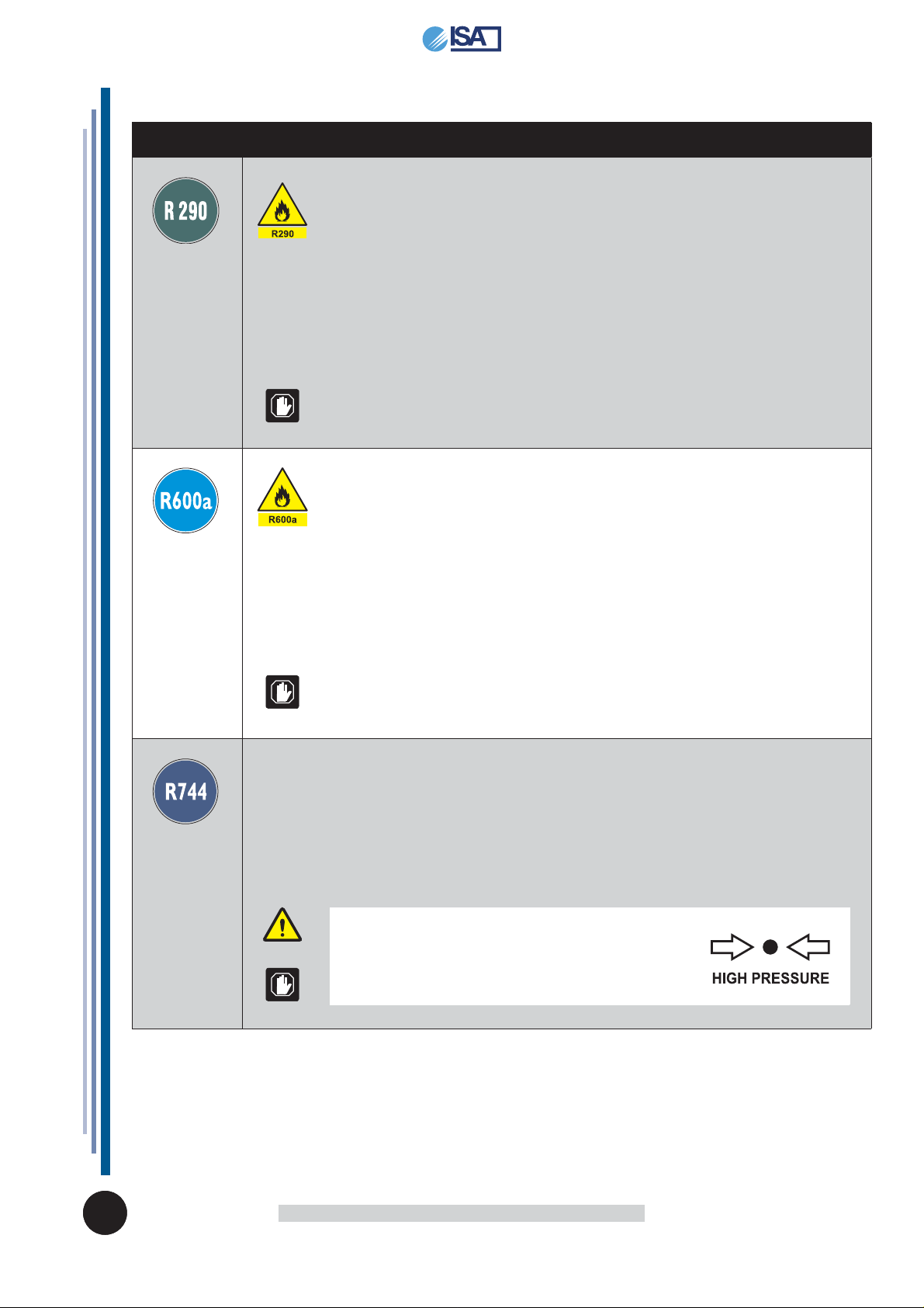
6.13 REFRIGERANTS (where applicable)
REFRIGERANT DESCRIPTION
The refrigerant R290 is a gas that is compatible with the environment, but
highly fl ammable.
Pay close attention during transport, installation and that the destruction not
to damage the refrigerant pipelines.
IN THE EVENT OF DAMAGE:
Keep fl ames or sources of ignition away from the appliance. Properly ventilate
the premises for a few minutes. Turn the unit off, pull the plug. Inform
customer support service. The more refrigerant containing an appliance, the
greater must be the environment in which there is the unit. In areas too small,
in the event of leakage can form a fl ammable mixture of air and gas. The
volume of the room where the appliance is installed must be at least
19 m³ for each cooling system present in the room.
WARNING
Maintenance must be performed by qualifi ed personnel that has been to work
with fl ammable refrigerants.
The refrigerant R600a is a gas that is compatible with the environment, but
highly fl ammable.
Pay close attention during transport, installation and that the destruction not
to damage the refrigerant pipelines.
IN THE EVENT OF DAMAGE:
Keep fl ames or sources of ignition away from the appliance. Properly ventilate
the premises for a few minutes. Turn the unit off, pull the plug. Inform
customer support service. The more refrigerant containing an appliance, the
greater must be the environment in which there is the unit. In areas too small,
in the event of leakage can form a fl ammable mixture of air and gas. The
volume of the room where the appliance is installed must be at least
17 m³ for each cooling system present in the room.
WARNING
Maintenance must be performed by qualifi ed personnel that has been to work
with fl ammable refrigerants.
IT EN
The refrigerant R744 is a gas that is compatible with the environment.
Pay close attention during transport, installation and that the destruction not
to damage the refrigerant pipelines.
IN THE EVENT OF DAMAGE:
Keep away from the fl ame or ignition sources. Properly ventilate the premises
for a few minutes. Turn the unit off, pull the plug. Inform customer support
service.
WARNING
The refrigerant system is High Pressure.
Do not tamper with the system, but call a
specialised and qualifi ed technician before disassembly.
Maintenance must be performed exclusively by
qualifi ed staff.
KELLY
USE AND MAINTENANCE MANUAL
428000587
037
11
7. DISPOSAL OF WASTE MATERIAL
During normal operation, the appliance does not generate any environmental contamination. At the
end of its life cycle, or if it is necessary to proceed to permanent decommissioning, we recommend
following the procedures below:
DISPOSAL (User)
The symbol, applied to either the product or its packaging, indicates that the product should not be
considered as normal domestic waste, but should be taken to a waste collection point for the recycling
of electrical and electronic appliances. The correct disposal of this product helps to prevent potential
negative consequences that might derive from inadequate product disposal. For detailed information
about recycling this product, contact your council, your local waste collection service or the store where
you purchased the product.
PROCEDURE FOR DISPOSAL and RECYCLING AT THE END OF APPLIANCE
LIFE SPAN (AUTHORISED BODIES)
• Switch off the equipment and unplug the power supply cable.
• Remove the lamps (if installed). These should be disposed of separately.
• Remove the power units and the electronic cards. These should be disposed of separately.
• Remove all the independent parts (grids, casings, profi les, etc.) and group them according to
shared features in order to access the heat exchangers, pipes, cables, etc. and be careful not to
damage the cooling circuit.
• Remove all mobile parts (doors, sliding doors, glass parts, etc.) and group the various materials
according to their features.
• Check the type of refrigerant on the plate positioned inside the counter; extract the refrigerant and
dispose of it through authorised services.
• Disconnect the evaporator, the condenser, the compressor, the pipes and fans. These are made of
copper, aluminium, steel and plastic and should therefore disposed of separately.
• On removal of all guards and the various components from the frame, separate the different types
of material making up the appliance (plastic, sheet steel, polyurethane, copper, etc) and collect
them separately.
All recyclable materials and waste should be processed and recycled by professionals, in compliance
with the laws in the country in question.
The company responsible for recycling the materials should be registered and certifi ed as a waste
disposal service in accordance with the country in question
Attention
Illegal disposal of the product by the owner will result in administrative sanctions as required by current laws.
Disposal of the product should comply with current laws on the disposal of coolant liquids
and mineral oils.
Important
If the crossed wheelie bin sign is not present on the appliance, it means that the disposal of the
product is not the manufacturer's responsibility. In this case, the Regulations regarding the disposal
of waste in force are valid.
Additional information
Further information on the disposal of liquid coolant, oils and other substances is available on the
safety data sheet corresponding to the substance itself.
KELLY
USE AND MAINTENANCE MANUAL
428000587
037
12
IT
EN
8. INSTALLATION
This manual supplies the information necessary for correct unpacking, procedures for
positioning and connection to mains electricity.
8.1 STORAGE AND UNPACKING
The appliance, with or without the packaging, should be carefully stored inside warehouses or in areas
away from the elements and direct sunlight, at a temperature between 0 and +40 °C.
The appliance should only be moved by qualifi ed personnel operating
forklift trucks, the power of which should be suited to handling the weight
of the product.
During said operation the appliance MUST placed on the special pallet supplied.
Unpack the appliance by removing the screws fi xing it to the pallet.
All packaging materials are recyclable and should be disposed of in accordance with local regulations.
Please destroy "plastic" bags to prevent them from becoming hazardous to children (suffocation).
8.2 INSTALLATION - POSITIONING - ENVIRONMENTAL CONDITIONS
Attention
A dry room that can be ventilated is the suitable location for the appliance's installation. There
should be a good air fl ow around the compressor/condensing unit. Therefore the area around the
unit should not be obstructed by boxes or other objects.
Position the appliance away from heat sources (radiators, stoves of all types, etc.) and away from
the effects of continuous currents of air (e.g. caused by fans, air conditioning vents, etc.). If it is
unavoidable to install near a heat source, use a suitable insulating plate,
Also avoid exposure to direct sunlight; all of this causes the temperature inside the refrigerated
compartment to rise with negative consequences on operation and energy consumption. Do not use
the appliance outdoors and do not leave it exposed to rain.
8.3 ELECTRIC CONNECTION
Attention
Check that the network voltage matches the one displayed on the identifi cation plate of the
appliance, and that the power is adequate.
Check on the socket that the power supply voltage provides rated voltage (±10%) when you start
up the compressor.
The plug should be directly connected to the electrical socket. It is forbidden to connect the plug to
the socket by means of multiple socket extensions or adaptors.
The plant power supply socket must be fi tted with a disconnection device from the mains electricity
(dimensioned to the load and in compliance with Standards in force), which guarantees complete
disconnection in category III (3) over-voltage conditions and therefore protects the circuits against
earth faults, overloads and short circuits.
Do not route the electricity cable in passageways.
Attention
Earthing is necessary and mandatory by law.
IT EN
KELLY
USE AND MAINTENANCE MANUAL
428000587
037
13
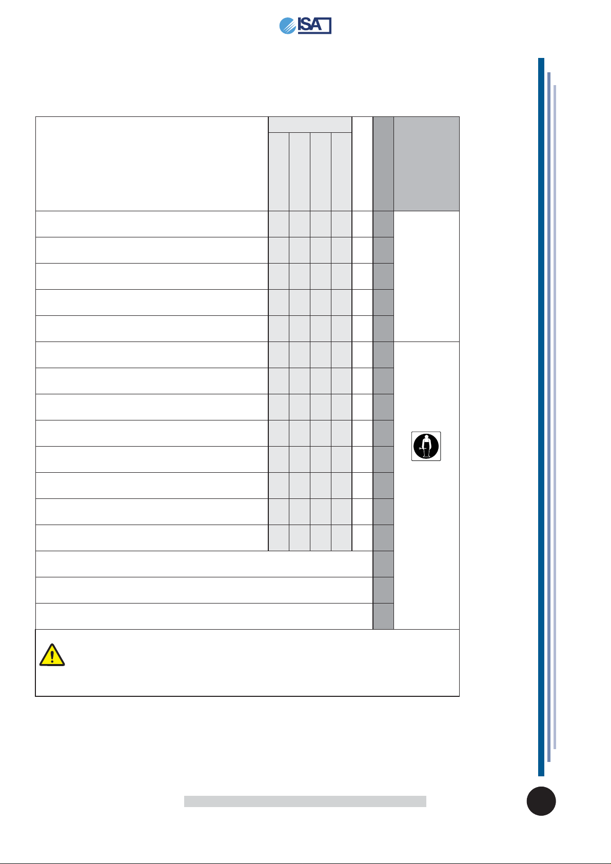
9. MAINTENANCE
The Staff in charge of the appliance must control and respect the expiry dates for maintenance,
given in the table below, calling the authorised Technical After-sales assistance when indicated.
OPERATION FREQUENCY
Depending on the
Use and Necessity
Monthly
six-month
CLEANING THE EXTERNAL SURFACES
CLEANING THE ACCESSIBLE INTERNAL PARTS
(without the use of tools)
CONTROL POWER SUPPLY CABLE,
PLUGS AND / OR ELECTRICAL SOCKETS
INTEGRITY CONTROL SEAL
FILTER CLEANING CONDENSING UNIT
(whenever present)
CLEANING THE DEFROSTING WATER COLLECTION TRAY
CONDENSER CLEANING
CHECK COMPRESSORE OIL LEVEL
(whenever present)
XX
XX
XX
XX
XX
XX
XXX
XX
Annual
ORDINARY
EXTRAORDINARY
AUTHORISED
PERSONNEL
USER
AIR TANK DRAINING
(whenever present)
CONTROL PNEUMATIC CONNECTIONS
(whenever present)
INTEGRITY CONTROL PIPE COOLING SYSTEM
INSPECTION OF CABLES
INTERNAL CONNECTIONS AND POWER
CLEANING CONDENSATE DRYING SPONGES
(whenever present)
LAMP / LED REPLACEMENT
(whenever present)
CONTROL PANEL REPLACING
(electronic control unit - thermostat - etc)
REPLACEMENT POWER SUPPLY CABLE, PLUGS AND / OR ELECTRICAL SOCKETS
XX
XX
XX
XX
XX
X
X
X
TECHNICAL
ASSISTANCE
SERVICE
Attention
After all maintenance it is mandatory to perform all electric safety tests in agreement with the IEC
EN 50106 Standard.
KELLY
USE AND MAINTENANCE MANUAL
428000587
037
14
IT
EN

10. FAULTS - TECHNICAL AFTER-SALES ASSISTANCE
If the appliance is not working properly or stops working, before contacting the Customer support centre, check
the following:
FAULT CAUSE SOLUTION AUTHORISED
THE APPLIANCE IS
NOT WORKING
THE INTERNAL TEMPERATURE
IS NOT LOW
ENOUGH
THE COMPRESSOR
DOES NOT
START-UP
OR OPERATES
FOR A FEW
MOMENTS
Blown protective fuse Previously fi nd the cause of the intervention
The master switch is open Close the master switch.
The plug is not inserted Insert the plug.
Electric black-out If the black-out should be prolonged, transfer the product
Evaporator/s obstructed completely by ice
Wrong setting temperature Set the appropriate temperature.
The appliance is affected by
draughts or is exposed to
direct or refl ected sunlight
Insuffi cient cooling air fl ow
rate of the air condenser
Internal fans at standstill or with fans damage TECHNICAL
Internal ventilation is too high
Thermostat / Electronic control
unit is not effi cient
Air condenser blocked by dust
or dirt in general
Insuffi cient refrigerant
load in the cooling system
No electric power supply
to the appliance
The power supply voltage is
too low
Temperature set too high If the set temperature is higher than that of the air in the dis-
The pressure switch (if any)
was activated at maximum
pressure
of the switch, and then re-introduce the new fuse.
into an appropriate cold storage container.
Carry out an additional defrosting cycle. USER
Remove any draughts and prevent any direct or refl ected
sunlight.
Remove anything that may affect air fl ow inside the condens-
ing unit (paper sheets, cardboard, grids with an insuffi cient
number of holes, etc.).
Replace the electronic control board.
If the control unit is set up especially for must R290 refrigerant,
it must only be replaced with an original replacement from
ISA.
Replace the temperature probes only after checking which of
the two is not operating effi ciently.
Clean the condensing unit thoroughly.
The air condenser or MAINTENANCE FREE, in particular heavy
environments (eg presence of dust, the presence of excessive
moisture, oiled vapours etc..) in order to avoid performance
loss, needs accurate cleaning.
Find the cause behind the lower amounts of coolant and
eliminate it. Top up the coolant. If necessary, empty the system before topping up.
Check if there is a power cut.
Close the various switches on the power supply line.
Check that the network voltage of the power supply cable is
220V +/- 10%.
play area, the compressor does not activate itself.
Set a more suitable temperature if the current value is not
low enough
Check the reasons why the pressure switch is operating
at maximum pressure levels, such as: air condensing unit
blocked, condensing unit fan stopped, ambient temperature
too high, pressure switch broken.
PERSONNEL
UTILIZZATORE
ASSISTANCE
USER
TECHNICAL
ASSISTANCE
IT EN
KELLY
USE AND MAINTENANCE MANUAL
428000587
037
15

10.1 ALARMS LIST (where present)
ALARM DESCRIPTION OUTPUTS AUTHORISED
P1
E0
P2
E1
HA
HI
LA
LO
EA
IA
CB
ETc
RTF
EE Machine parameter error. • The instrument is damaged. It must be replaced.
EF Operating parameters error. • The instrument is damaged. It must be replaced.
Broken thermostat probe.
Compressor output according to
“COn” and “COF parameters
Broken evaporator probe.
Set time for defrosting.
High temperature alarm. • The alarm stops automatically on reaching the temperature set.
Low temperature alarm. • The alarm stops automatically on reaching the temperature set.
External alarm. • The external alarm stops after the digital infeed is deactivated, it is restored
Real time clock is broken. • Reset the clock.
• The alarm starts a few seconds after the probe breaks down; it stops a few
seconds after the probe starts working again properly.
• We recommend checking the probe connections before replacing it.
• The alarm starts a few seconds after the probe breaks down; it stops a few
seconds after the probe starts working again properly.
• We recommend checking the probe connections before replacing it.
• Check programming.
• Check programming.
automatically.
• The alarm is linked to the intervention of the pressure switch and/or the compressor circuit breaker, when present.
• If the alarm does not stop, replace the clock.
PERSONNEL
KELLY
USE AND MAINTENANCE MANUAL
428000587
037
16
IT
EN

11. TECHNICAL SPECIFICATIONS (80)
DRY HOT DISPLAY CABINETS (S)
MODELS
100 150 200 AE 90
805
128
960
100
1170
150 200
AE 90
998 1498 1998
1019
1019
805
1019
805
1019
100 150 200 AE 90
SSSS
L (mm) 998 1498 1998 1019
External dimensdions
Refrigeration NA NA NA NA
Defrosting NA NA NA NA
Climate Class N° 3333
Environmental conditions °C / %RH 25 / 60 25 / 60 25 / 60 25 / 60
Product class
Product temperature °C +65 / +80 +65 / +80 +65 / +80 +65 / +80
Temperature range °C NA NA NA NA
Safety class (CEI EN 60335-2-89) N° / °C (ambient) 5 / 43 ± 2°C 5 / 43 ± 2°C 5 / 43 ± 2°C 5 / 43 ± 2°C
Refrigerant (GWP) NA NA NA NA
Power supply V / ph / Hz 230 / 1 / 50 230 / 1 / 50 230 / 1 / 50 230 / 1 / 50
Electrical input (Standard) W / A 1250 / 6 1900 / 9,2 2500 / 12,1 1250 / 6
Electrical input (Defrosting) W / A NA NA NA NA
Weight (net) Kg 90 110 130 110
NA: Not Applicable
P (mm) 805 805 805 805
H (mm) 1170 1170 1170 1170
SSSS
IT EN
KELLY
USE AND MAINTENANCE MANUAL
428000587
037
17

11. TECHNICAL SPECIFICATIONS (80)
PASTRY DISPLAY CABINETS AT STATIC REFRIGERATION
MODELS
110 125 164 200
805
240
960
110
1098
1170
125
1248 1638 1998
164
200
110 125 164 200
RS TN RS TN RS TN RS TN
L (mm) 1098 1248 1638 1998
External dimensdions
Refrigeration Static Static Static Static
Defrosting
Climate Class N° 3333
Environmental conditions °C / %RH 25 / 60 25 / 60 25 / 60 25 / 60
Product class
Product temperature °C +1 / +10 +1 / +10 +1 / +10 +1 / +10
Temperature range °C NA NA NA NA
Safety class (CEI EN 60335-2-89) N° / °C (ambient) 5 / 43 ± 2°C 5 / 43 ± 2°C 5 / 43 ± 2°C 5 / 43 ± 2°C
Refrigerant (GWP)
Power supply V / ph / Hz 230 / 1 / 50 230 / 1 / 50 230 / 1 / 50 230 / 1 / 50
Electrical input (Standard) W / A
Electrical input (Defrosting) W / A 50 / 0,3 50 / 0,3 70 / 0,4 120 / 0,5
Weight (net) Kg 150 160 170 190
NA: Not Applicable
P (mm) 805 805 805 805
H (mm) 1170 1170 1170 1170
Off Cycle Off Cycle Off Cycle Off Cycle
H1 H1 H1 H1
R404A (3784) R404A (3784) R404A (3784) R404A (3784)
350 / 2 350 / 2 450 / 2,8 540 / 3,7
KELLY
USE AND MAINTENANCE MANUAL
428000587
037
18
IT
EN

11. TECHNICAL SPECIFICATIONS (80)
PASTRY DISPLAY CABINETS AT VENTILATED REFRIGERATION
MODELS
75 100 150 200 AE90
805
128
960
75
748
100 150 200
998 1498 1998
1170
AE 90
1019
1019
805
1019
805
1019
75 100 150 200 AE 90
RV TN RV TN RV TN RV TN RV TN
L (mm) 748 958 1498 1998 1019
External dimensdions
Refrigeration Ventilated Ventilated Ventilated Ventilated Ventilated
Defrosting
Climate Class N° 3 3 3 3 3
Environmental conditions °C / %RH 25 / 60 25 / 60 25 / 60 25 / 60 25 / 60
Product class
Product temperature °C +1 / +10 +1 / +10 +1 / +10 +1 / +10 +1 / +10
Temperature range °C NA NA NA NA NA
Safety class (CEI EN 60335-2-89) N° / °C (ambient) 5 / 43 ± 2°C 5 / 43 ± 2°C 5 / 43 ± 2°C 5 / 43 ± 2°C 5 / 43 ± 2°C
Refrigerant (GWP)
Power supply V / ph / Hz 230 / 1 / 50 230 / 1 / 50 230 / 1 / 50 230 / 1 / 50 230 / 1 / 50
Electrical input (Standard) W / A
Electrical input (Defrosting) W / A 300 / 1,3 300 / 1,3 350 / 1,6 400 / 1,8 300 / 1,3
Weight (net) Kg 70 90 110 130 130
NA: Not Applicable
P (mm) 805 805 805 805 805
H (mm) 1170 1170 1170 1170 1170
Off Cycle Off Cycle Off Cycle Off Cycle Off Cycle
H1 H1 H1 H1 H1
R404A (3784) R404A (3784) R404A (3784) R404A (3784) R404A (3784)
600 / 2,2 600 / 2,2 800 / 3 900 / 3,5 600 / 2,2
IT EN
KELLY
USE AND MAINTENANCE MANUAL
428000587
037
19

11. TECHNICAL SPECIFICATIONS (80)
ICE CREAM DISPLAY CABINETS AT VENTILATED REFRIGERATION
MAXIMA
MODELS
12 18 24
805
175
960
12
1068
1170
18
1563 2058
24
12 18 24
RV TB RV TB RV TB
L (mm) 1068 1563 2058
External dimensdions
Refrigeration Ventilated Ventilated Ventilated
Defrosting
Climate Class N° 4 4 4
Environmental conditions °C / %RH 30 / 55 30 / 55 30 / 55
Product class
Product temperature °C -16 / -14 -16 / -14 -16 / -14
Temperature range °C NA NA NA
Safety class (CEI EN 60335-2-89) N° / °C (ambient) 5 / 43 ± 2°C 5 / 43 ± 2°C 5 / 43 ± 2°C
Refrigerant (GWP)
Power supply V / ph / Hz 230 / 1 / 50 230 / 1 / 50 230 / 1 / 50
Electrical input (Standard) W / A
Electrical input (Defrosting) W / A 1520 / 7,3 2470 / 12,2 2600 / 12,9
Weight (net) Kg 200 280 375
NA: Not Applicable
P (mm) 805 805 805
H (mm) 1170 1170 1170
Off Cycle Off Cycle Off Cycle
SSS
R404A (3784) R404A (3784) R404A (3784)
790 / 3,8 1350 / 6,5 1800 / 7,7
KELLY
USE AND MAINTENANCE MANUAL
428000587
037
20
IT
EN

11. TECHNICAL SPECIFICATIONS (80)
ICE CREAM DISPLAY CABINETS AT VENTILATED REFRIGERATION
MAXIMA
MODELS
12 18 24
DISPLAY CONTAINERS ARRANGEMENT
lt 4.75
(260x157x170H)
lt 9
(530x162x100H)
12
18
1812
96
24
12
24
IT EN
KELLY
USE AND MAINTENANCE MANUAL
428000587
037
21

11. TECHNICAL SPECIFICATIONS (100)
BREAD DISPLAY CABINETS
MODELS
164
983
250
1170
960
164
1638
164
L (mm) 1638
External dimensdions
Refrigeration NA
Defrosting NA
Climate Class N° 3
Environmental conditions °C / %RH 25 / 60
Product class NA
Product temperature °C NA
Temperature range °C NA
Safety class (CEI EN 60335-2-89) N° / °C (ambient) 5 / 43 ± 2°C
Refrigerant (GWP) NA
Power supply V / ph / Hz 230 / 1 / 50
Electrical input (Standard) W / A 140 / 0,6
Electrical input (Defrosting) W / A NA
Weight (net) Kg 220
NA: Not Applicable
P (mm) 983
H (mm) 1170
KELLY
USE AND MAINTENANCE MANUAL
428000587
037
22
IT
EN

11. TECHNICAL SPECIFICATIONS (100)
DISPLAY CABINETS “PIZZA”
MODELS
164
983
250
1170
960
164
1638
164
L (mm) 1638
External dimensdions
Refrigeration NA
Defrosting NA
Climate Class N° 3
Environmental conditions °C / %RH 25 / 60
Product class NA
Product temperature °C NA
Temperature range °C NA
Safety class (CEI EN 60335-2-89) N° / °C (ambient) 5 / 43 ± 2°C
Refrigerant (GWP) NA
Power supply V / ph / Hz 230 / 1 / 50
Electrical input (Standard) W / A 140 / 0,6
Electrical input (Defrosting) W / A NA
Weight (net) Kg 220
NA: Not Applicable
P (mm) 983
H (mm) 1170
IT EN
KELLY
USE AND MAINTENANCE MANUAL
428000587
037
23

11. TECHNICAL SPECIFICATIONS (100)
DRY HOT DISPLAY CABINETS (S)
MODELS
110 164
983
250
1170
960
110
1098
164
1638
110 164
SS
L (mm) 1098 1638
External dimensdions
Refrigeration NA NA
Defrosting NA NA
Climate Class N° 3 3
Environmental conditions °C / %RH 25 / 60 25 / 60
Product class
Product temperature °C +65 / +80 +65 / +80
Temperature range °C NA NA
Safety class (CEI EN 60335-2-89) N° / °C (ambient) 5 / 43 ± 2°C 5 / 43 ± 2°C
Refrigerant (GWP) NA NA
Power supply V / ph / Hz 230 / 1 / 50 230 / 1 / 50
Electrical input (Standard) W / A 1300 / 5,7 1900 / 8,3
Electrical input (Defrosting) W / A NA NA
Weight (net) Kg 150 180
NA: Not Applicable
P (mm) 983 983
H (mm) 1170 1170
SS
KELLY
USE AND MAINTENANCE MANUAL
428000587
037
24
IT
EN

11. TECHNICAL SPECIFICATIONS (100)
BAIN-MARIE HOT DISPLAY CABINETS (S)
MODELS
110 164
983
250
1170
960
110
1098
164
1638
110 164
BM BM
L (mm) 1098 1638
External dimensdions
Refrigeration NA NA
Defrosting NA NA
Climate Class N° 3 3
Environmental conditions °C / %RH 25 / 60 25 / 60
Product class
Product temperature °C +65 / +80 +65 / +80
Temperature range °C NA NA
Safety class (CEI EN 60335-2-89) N° / °C (ambient) 5 / 43 ± 2°C 5 / 43 ± 2°C
Refrigerant (GWP) NA NA
Power supply V / ph / Hz 230 / 1 / 50 230 / 1 / 50
Electrical input (Standard) W / A 1300 / 5,7 1900 / 8,3
Electrical input (Defrosting) W / A NA NA
Weight (net) Kg 150 180
NA: Not Applicable
P (mm) 983 983
H (mm) 1170 1170
SS
IT EN
KELLY
USE AND MAINTENANCE MANUAL
428000587
037
25

11. TECHNICAL SPECIFICATIONS (100)
PASTRY DISPLAY CABINETS AT STATIC REFRIGERATION
MODELS
110 164 218
983
250
1170
960
110
1098
164
1638
218
2178
110 164 218
RS TN RS TN RS TN
L (mm) 1098 1638 2178
External dimensdions
Refrigeration Static Static Static
Defrosting
Climate Class N° 3 3 3
Environmental conditions °C / %RH 25 / 60 25 / 60 25 / 60
Product class
Product temperature °C +1 / +10 +1 / +10 +1 / +10
Temperature range °C NA NA NA
Safety class (CEI EN 60335-2-89) N° / °C (ambient) 5 / 43 ± 2°C 5 / 43 ± 2°C 5 / 43 ± 2°C
Refrigerant (GWP)
Power supply V / ph / Hz 230 / 1 / 50 230 / 1 / 50 230 / 1 / 50
Electrical input (Standard) W / A
Electrical input (Defrosting) W / A 380 / 1,8 400 / 1,9 490 / 2,3
Weight (net) Kg 150 180 210
NA: Not Applicable
P (mm) 983 983 983
H (mm) 1170 1170 1170
Off Cycle Off Cycle Off Cycle
H1 H1 H1
R404A (3784) R404A (3784) R404A (3784)
700 / 3,8 730 / 3,9 880 / 4,8
KELLY
USE AND MAINTENANCE MANUAL
428000587
037
26
IT
EN

11. TECHNICAL SPECIFICATIONS (100)
PASTRY DISPLAY CABINETS AT STATIC REFRIGERATION
MODELS
110 1C 164 2C 218 2C
983
250
1170
960
110
1098
164
1638
218
2178
110 164 218
RS TN RS TN RS TN
1C 2C 2C
L (mm) 1098 1638 2178
External dimensdions
Refrigeration Static Static Static
Defrosting
Climate Class N° 3 3 3
Environmental conditions °C / %RH 25 / 60 25 / 60 25 / 60
Product class
Product temperature °C +1 / +10 +1 / +10 +1 / +10
Temperature range °C NA NA NA
Safety class (CEI EN 60335-2-89) N° / °C (ambient) 5 / 43 ± 2°C 5 / 43 ± 2°C 5 / 43 ± 2°C
Refrigerant (GWP)
Power supply V / ph / Hz 230 / 1 / 50 230 / 1 / 50 230 / 1 / 50
Electrical input (Standard) W / A
Electrical input (Defrosting) W / A 380 / 1,8 400 / 1,9 490 / 2,3
Weight (net) Kg 165 195 225
NA: Not Applicable
P (mm) 983 983 983
H (mm) 1170 1170 1170
Off Cycle Off Cycle Off Cycle
H1 H1 H1
R404A (3784) R404A (3784) R404A (3784)
700 / 3,8 730 / 3,9 880 / 4,8
IT EN
KELLY
USE AND MAINTENANCE MANUAL
428000587
037
27

11. TECHNICAL SPECIFICATIONS (100)
PASTRY DISPLAY CABINETS AT VENTILATED REFRIGERATION
MODELS
110 164 218
983
144
1170
960
110
1098
164
1638
218
2178
110 164 218
RV TN RV TN RV TN
L (mm) 1098 1638 2178
External dimensdions
Refrigeration Ventilated Ventilated Ventilated
Defrosting
Climate Class N° 3 3 3
Environmental conditions °C / %RH 25 / 60 25 / 60 25 / 60
Product class
Product temperature °C +1 / +10 +1 / +10 +1 / +10
Temperature range °C NA NA NA
Safety class (CEI EN 60335-2-89) N° / °C (ambient) 5 / 43 ± 2°C 5 / 43 ± 2°C 5 / 43 ± 2°C
Refrigerant (GWP)
Power supply V / ph / Hz 230 / 1 / 50 230 / 1 / 50 230 / 1 / 50
Electrical input (Standard) W / A
Electrical input (Defrosting) W / A 350 / 1,5 400 / 1,7 430 / 1,9
Weight (net) Kg 150 180 210
NA: Not Applicable
P (mm) 983 983 983
H (mm) 1170 1170 1170
Off Cycle Off Cycle Off Cycle
H1 H1 H1
R404A (3784) R404A (3784) R404A (3784)
800 / 2,9 800 / 2,9 900 / 3,3
KELLY
USE AND MAINTENANCE MANUAL
428000587
037
28
IT
EN

11. TECHNICAL SPECIFICATIONS (100)
PASTRY DISPLAY CABINETS AT VENTILATED REFRIGERATION
“praline”
MODELS
110 164 218
983
144
1170
960
110
1098
164
1638
218
2178
110 164 218
RV TN RV TN RV TN
L (mm) 1098 1638 2178
External dimensdions
Refrigeration Ventilated Ventilated Ventilated
Defrosting
Climate Class N° 3 3 3
Environmental conditions °C / %RH 25 / 60 25 / 60 25 / 60
Product class
Product temperature °C +15 / +18 +15 / +18 +15 / +18
Temperature range °C NA NA NA
Safety class (CEI EN 60335-2-89) N° / °C (ambient) 5 / 43 ± 2°C 5 / 43 ± 2°C 5 / 43 ± 2°C
Refrigerant (GWP)
Power supply V / ph / Hz 230 / 1 / 50 230 / 1 / 50 230 / 1 / 50
Electrical input (Standard) W / A
Electrical input (Defrosting) W / A 350 / 1,5 400 / 1,7 430 / 1,9
Weight (net) Kg 150 180 210
NA: Not Applicable
P (mm) 983 983 983
H (mm) 1170 1170 1170
Off Cycle Off Cycle Off Cycle
SSS
R404A (3784) R404A (3784) R404A (3784)
800 / 2,9 800 / 2,9 900 / 3,3
IT EN
KELLY
USE AND MAINTENANCE MANUAL
428000587
037
29

11. TECHNICAL SPECIFICATIONS (100)
ICE CREAM DISPLAY CABINETS AT VENTILATED REFRIGERATION
SUPERCAPRI
MODELS
12 18 24 12+12
1038
156
1170
960
12
1142 1672 2182
18
24
12+12
2182
12 18 24 12+12
RV TB RV TB RV TB RV TB
L (mm) 1142 1672 2182 2182
External dimensdions
Refrigeration Ventilated Ventilated Ventilated Ventilated
Defrosting
Climate Class N° 7777
Environmental conditions °C / %RH 35 / 75 35 / 75 35 / 75 35 / 75
Product class
Product temperature °C -16 / -14 -16 / -14 -16 / -14 -16 / -14
Temperature range °C -20 / +2 -20 / +2 -20 / +2 -20 / +2
Safety class (CEI EN 60335-2-89) N° / °C (ambient) 5 / 43 ± 2°C 5 / 43 ± 2°C 5 / 43 ± 2°C 5 / 43 ± 2°C
Refrigerant (GWP)
Power supply V / ph / Hz 230 / 1 / 50 230 / 1 / 50 230 / 1 / 50 230 / 1 / 50
Electrical input (Standard) W / A
Electrical input (Defrosting) W / A 3500 / 15,6 4020 / 18 5050 / 20,5 5900 / 25
Weight (net) Kg 235 330 437 470
NA: Not Applicable
P (mm) 1038 1038 1038 1038
H (mm) 1170 1170 1170 1170
Reverse Cycle Reverse Cycle Reverse Cycle Reverse Cycle
SSSS
R404A (3784) R404A (3784) R404A (3784) R404A (3784)
1650 / 7,8 2000 / 8,9 3140 / 15 2850 / 14
KELLY
USE AND MAINTENANCE MANUAL
428000587
037
30
IT
EN

11. TECHNICAL SPECIFICATIONS (100)
ICE CREAM DISPLAY CABINETS AT VENTILATED REFRIGERATION
SUPERCAPRI
MODELS
12 18 24 12+12
DISPLAY CONTAINERS ARRANGEMENT
lt 5
(360x165x120H)
lt 7
(360x165x150H)
lt 5
(360x250x80H)
lt 10
(360x250x120H)
lt 12
(360x250x150H)
12
18
18 2412 12+12
12 168 8+8
24
12+12
IT EN
KELLY
USE AND MAINTENANCE MANUAL
428000587
037
31

11.1 POSITIONING / LEVELING
Attention
The appliance is fi tted with adjustable leveling feet in height.
Level the appliance.
11.2 LOAD LIMITS
Attention
It is fundamental not to exceed the load limits indicated in order not to alter the correct air circulation
and thus prevent a high product temperature.
KELLY
USE AND MAINTENANCE MANUAL
428000587
037
32
IT
EN

12. CONTROL PANEL
The equipment covered by this manual may be equipped with an electronic control and supervision that
despite being an integral part of the ‘appliance is equipped with a manual in itself to which reference is made
for every detail.
IT EN
KELLY
USE AND MAINTENANCE MANUAL
428000587
037
33

13. CLEANING
EXTERNAL
STAINLESS STEEL Only use warm water and non-aggressive detergents and then rinse
ACRYLIC OR POLYCARBONATE Wash with lukewarm water, using a soft cloth or a chamois cloth.
and dry using a soft cloth.
Do not use detergents, alcohol, acetone or solvents.
Do not use abrasive cloths or sponges.
GLASS Only use products specifi cally designed for cleaning glass.
We do not recommend using tap water, which may leave calcium deposits
on the surface of the glass.
INTERNAL
Attention
Do not scrape the ice from the walls with pointed tools, the surfaces will be ruined.
Do no use high pressure appliances (e.g. steam generators).
• Remove the product contained in the cabinet and put it immediately in a relevant cold storage container
in order to guarantee correct preservation.
• Turn the appliance off.
• Remove the sliding doors and internal grids. Wait for suffi cient time for any ice present on the inner
walls to melt completely before starting cleaning operations.
• Remove the drain cap at the bottom of the tank to allow defrosting water to fl ow out (if present).
• Clean the side walls and bottom of the tank using a non-aggressive detergent, warm water and a cloth
or non-abrasive sponge. Do not use pointed tools. Rinse well and dry using an absorbent cloth.
• Re-mount the sliding doors and internal grids. Switch the appliance on and leave the counter to cool for
at least 2 hours before re-introducing the foodstuffs.
CONDENSING UNIT
Attention
Remove the protective grilles.
Clean the condensing unit using a suction brush.
Clean the condenser with a soft bristle brush; make sure you do not
bend the condensing unit springs whilst cleaning it.
KELLY
USE AND MAINTENANCE MANUAL
428000587
037
34
IT
EN

13. CLEANING
DEFROST WATER COLLECTION TRAY
SLIDING GLASS PANEL
Attenzione
Clean based on use and as needed and in certain
environmental conditions (e.g., high humidity,
low environmental temperature, presence of dust,
etc.) in order to avoid the incorrect and complete
evaporation of the water and/or the presence of
unpleasant odours.
Sanitize the tray with specifi c products.
The sliding glass panels must be cleaned periodically
using normal detergents for glass.
Attention
The panels are realised in toughened and heatrefl ecting glass and the frame is in special material,
which guaranteed excellent sliding.
Clean the frame periodically in order to maintain
smooth sliding of the panels.
IT EN
KELLY
USE AND MAINTENANCE MANUAL
428000587
037
35

14. PROLONGED APPLIANCE SWITCH-OFF
• Remove the product contained in the cabinet and put it immediately in a relevant cold storage container in
order to guarantee correct preservation.
• Open the appliance and wait for it to reach room temperature and then clean it.
• Leave the sliding glass panels open by 2-3 cm so as to guarantee circulation of the air and prevent the
formation of mould and bad smells inside the appliance.
• The appliance, with or without the packaging, should be carefully stored inside warehouses or in areas
away from the elements and direct sunlight, at a temperature between 0 and +40 °C.
KELLY
USE AND MAINTENANCE MANUAL
428000587
037
36
IT
EN

Attachment 1 - DECLARATION OF CONFORMITY
DECLARATION OF CONFORMITY
We: ISA S.r.l.
Via del Lavoro, 5 - 06083 - Bastia Umbra (PG)
declare under our own responsibility, that the product:
Product: KELLY
Serial number: .....
To which this declaration refers, is in compliance with e following:
General electric safety Standard EN 60335-1/Ed.2002+Modifi cations A11:2004,A1:2004,A12:2006,A2:2006 + A13:2008
A15:2011. Particular requirements for commercial refrigerating appliances EN 60335-2-89/Ed.2010. Standard for Measuring Electromagnetic Fields (EMF) of Electrical Appliances EN 62233:2008, Directive 2006/95/EC of the European Parliament and the Council of 12th
December 2006 on the harmonisation of the Laws of Member States relating to electrical equipment for use within certain voltage limits
EN 62471/Ed.2009 Photo-biologic safety of lamps and lamp systems
ELECTROMAGNETIC COMPATIBILITY (EMC)
Limits and methods of measurement of radio interference characteristics of household appliances and similar motor-operated and
thermal appliances, of equipment, electrical appliances and similar equipment EN 55014-1 (valid until 2009: Ed.2000+Amendments
Minimum requirements for household appliances, tools and similar electrical appliances EN 55014-2 (Ed.1997+Amendment A1:2001)
Part 3: Limits – Section 2: Limits for harmonic current emissions (equipment input current=16A per phase)
EN61000-3-2 (valid until 2009:Ed.2000+Modifi cation A2:2005-or:Ed.2006) Part 3:Limits-Section 3:Limitation of voltage fl uctuations and
fl icker in low-voltage supply systems for equipment with rated current=16A EN61000-3-3 (Ed.1995+Modifi cations A1:2001,A2:2005)
Part 4:Testing and measurement techniques Section 2:Electrostatic discharge immunity test EN61000-4-2 (Ed.1995) Part 4:Testing and
measurement techniques Section 4: Electrical fast transient/burst immunity test EN61000-4-4 (Ed.1995)
PRESSURE EQUIPMENT DIRECTIVE (PED) 97/23/EC
As the equipment falls into a class lower than I, it is excluded from the PED’s application fi eld (art.1 par.3.6)
Regulation (CE) N.1935/2004 of the European Parliament and of the Council dated 27 October 2004 Regulation (CE) N.2023/2006 of
the Council dated 22 December, Directive 2008/39/CE of the Council dated 6 March 2008 Directive 2007/19/CE of the Council dated 30
March 2007 Directive 2005/79/CE of the Council dated 18 November 2005 Directive 2004/19/CE of the Council dated 10 March 2004
Directive 2004/1/CE of the Council dated 6 January 2004 Regulation (UE) 10/2011 of the Council dated 14 January 2011
Directive 2011/95/EC of the European Parliament and of the Council of 8th June 2011
Directive 2002/96/EC of the European Parliament and of the Council of 27th January 2003
Regulation (CE) n. 1907/2006 of the European parliament and council dated 18 December 2006 concerning the recording, evaluation,
authorisation and restriction of the chemical substances (REACH), which establishes a European Agency regarding chemical substances,
which modifi es the Directive 1999/45/CE and that repeals the Regulation (CEE) n. 793/93 of the Council and the regulation (CE) n.
1488/94 of the Commission 91/155/CEE, 93/105/CE and 2000/21/CE
SUBSTANCES THAT REDUCE THE OZONE LAYER
Regulation (CE) N. 1005/2009 dated 16 September 2009 (Offi cial Journal (OJ) of the European Union 31/10/2009 L286)
According to the requirements set by Directives: 2006/95/EC, 2004/108/EC, 2006/42/EC, 97/23/EC
MACHINERY SAFETY
A1:2001, A2:2002 - or: Ed.2006)
FOODSTUFF COMPATIBILITY
ROHS and WEEE
REACH
The person authorised to draw-up the Technical Folder is Mr. Minelli Maurizio (Technical Department Manager)
Bastia Umbra: 22 / 04 / 2014
(place and date of issue) Minelli Maurizio
Via del Lavoro 5 - 06083 Bastia Umbra (PG)
KELLY
IT EN
USE AND MAINTENANCE MANUAL
428000587
037
37

Attachment 2 - WIRING DIAGRAM - 412100329000
CE ELECTRONIC CONTROL BOARD
GD1 POWER SUPPLY LED
HL2 LED LAMP
I1 CABINET SWITCH
I2 LIGHTING SWITCH
S1 TEMPERATURE PROBE
S2 DEFROSTING PROBE
U1 COMPRESSOR
U2 CONDENSER FAN
U3 EVAPORATOR FAN
KELLY
USE AND MAINTENANCE MANUAL
428000587
037
38
IT
EN

Attachment 3 - WIRING DIAGRAM - 412100353000
ELECTRONIC CONTROL BOARD
POWER SUPPLY LED
LED LAMPI1CABINET SWITCHI2LIGHTING SWITCHR1RESIASTANCE SHELFS1TEMPERATURE PROBET1TRANSFORMER
CE
GD1
HL1
COMPRESSORU2CONDENSER FAN
U1
IT EN
KELLY
USE AND MAINTENANCE MANUAL
428000587
037
39

Attachment 4 - WIRING DIAGRAM - 412100355000
ELECTRONIC CONTROL BOARD
POWER SUPPLY LED
LED LAMPI1CABINET SWITCHI2LIGHTING SWITCHS1TEMPERATURE PROBEU1COMPRESSORU2CONDENSER FAN
CE
GD1
HL1
KELLY
USE AND MAINTENANCE MANUAL
428000587
037
40
IT
EN

Attachment 5 - WIRING DIAGRAM - 412100362000
CE ELECTRONIC CONTROL BOARD
I1 CABINET SWITCH
I2 LIGHTING SWITCH
L1 REACTO
L5 FLUORESCENT LAMP T8
R1 RESISTANCE SHELF
S1 TEMPERATURE PROBE
S2 DEFROSTING PROBE
U1 COMPRESSOR
U2 CONDENSER FAN
U3 EVAPORATOR FAN
U8 STARTER
IT EN
KELLY
USE AND MAINTENANCE MANUAL
428000587
037
41

Attachment 6 - WIRING DIAGRAM - 412136572100
KELLY
USE AND MAINTENANCE MANUAL
428000587
037
42
B1 SOLENOID VALVE S2 EVAPORATOR PROBE
B2 DEFROST VALVE S8 PRESSURE SWITCH
C5 ELECTRONIC CONTROL T6 HEATING GLASS TRANSFORMER
GD1 POWER SUPPLY LED T11 CONDENSER FAN THERMOSTAT
HL1 LED LIGHTING U1 COMPRESSOR
R5 FRONTAL FRAME ANTISWEET HEATER U2 CONDENSER FAN
R21 AIR IN CHANNEL ANTISWEET HEATER U3 EVAPORATOR FAN
R26 AIR OFF CHANNEL ANTISWEET HEATER V2 HEATING GLASS SIDE
S1 TEMPERATURE PROBE
IT
EN

Attachment 7 - WIRING DIAGRAM - 412136574100
IT EN
KELLY
USE AND MAINTENANCE MANUAL
428000587
037
43
B1 SOLENOID VALVE S1 TEMPERATURE PROBE
B2 DEFROST VALVE S2 EVAPORATOR PROBE
C5 ELECTRONIC CONTROL S8 PRESSURE SWITCH
GD1 POWER SUPPLY LED T6 HEATING GLASS TRANSFORMER
HL1 LED LIGHTING T11 CONDENSER FAN THERMOSTAT
R5 FRONTAL FRAME ANTISWEET HEATER U1 COMPRESSOR
R9 DELAY RELAY FOR 2 COMPRESSOR U2 CONDENSER FAN
R21 AIR IN CHANNEL ANTISWEET HEATER U3 EVAPORATOR FAN
R26 AIR OFF CHANNEL ANTISWEET HEATER V2 HEATING GLASS SIDE

Attachment 8 - WIRING DIAGRAM - 412138611300
KELLY
USE AND MAINTENANCE MANUAL
428000587
037
44
IT
EN

Attachment 8 - WIRING DIAGRAM - 412138611300
B1 SOLENOID VALVE FLOW
B2 DEFROSTING VALVE
B5 WATER VALVE
C5 ELECTRONIC CONTROL UNIT
GD1 POWER SUPPLY LED
HL1 LED LIGHTING
R5 FRONTAL FRAME ANTISWEET HEATER
R21 AIR IN CHANNEL ANTISWEET HEATER
R26 AIR OFF CHANNEL ANTISWEET HEATER
S1 TEMPERATURE PROBE
S2 EVAPORATOR PROBE
S8 PRESSURE SWITCH
T6 HEATING GLASS TRANSFORMER
T11 CONDENSER FAN THERMOSTAT
U1 COMPRESSOR
U2 CONDENSER FAN
U3 EVAPORATOR FAN
V2 EVAPORATOR FAN
1 INPUT STAGE POWER ELECTRONIC CONTROL UNIT
2 INPUT NEUTRAL POWER ELECTRONIC CONTROL UNIT
3 OUTPUT STAGE COMPRESSOR CONTROL
6 OUTPUT PHASE CONTROL SOLENOID VALVE
10 OUTPUT STAGE SUPPLY VALVE 4 WAY
14 OUTPUT NEUTRAL FAN CONDENSING
15 OUTPUT PHASE CONTROL FAN CONDENSING
FU1 FUSIBLE 2A
FU2 FUSIBLE 1A
KM1 ADDITIONAL CONTACT CONTACTOR
KM2 RELAY
M1 LINE COUNTER
M2 NEUTRAL COUNTER
M3 COMPRESSOR CONTROL
M9 DEFROSTING CONTROL
M11 PRESSURE SWITCH DIGITAL INPUT ALARM
M12 PRESSURE SWITCH DIGITAL INPUT ALARM
M19 FLOW CONTROL VALVE
M27 COMMON NEUTRAL
M28 FAN CONTROL DEFROST
M29 FAN CONTROL SPEED ADJUSTMENT
M30 NEUTRAL RESISTANCE CARTER COMPRESSOR
M31 CARTER COMPRESSOR LINE RESISTANCE
QF1 MOTOR PROTECTION + ADDITIONAL CONTACT
QS1 CIRCUIT BREAKER 32A 440V
QS2 CIRCUIT BREAKER COUNTER 10A
IT EN
KELLY
USE AND MAINTENANCE MANUAL
428000587
037
45

 Loading...