

Page 1
DATE: 19/03/2015 DOC.SIE10169 REV.13
CIRCUIT BREAKER ANALYZER
AND MICROOHMMETER
MOD. CBA2000
Shop for Power Metering products online at:
1.877.766.5412
www.PowerMeterStore.ca
Page 2

Doc. SIE10169 Rev. 13 Page 3 of 32
APPLICABLE STANDARDS ......................................................................................................................................... 4
1 INTRODUCTION ....................................................................................................................................................... 5
2 CHARACTERISTICS ................................................................................................................................................ 8
2.1 COIL DRIVING CIRCUITS ............................................................................................................................................ 8
2.2 MAIN CONTACT INPUTS ............................................................................................................................................. 8
2.3 AUXILIARY INPUTS AND OUTPUTS ............................................................................................................................. 8
2.4 INPUTS TIMING ........................................................................................................................................................... 9
2.5 ANALOG INPUT .......................................................................................................................................................... 9
2.5.1 Coil currents ...................................................................................................................................................... 9
2.5.2 High voltage analog inputs ............................................................................................................................... 9
2.5.3 Low voltage analog inputs ................................................................................................................................ 9
2.5.4 Digital transducers .......................................................................................................................................... 10
2.6 TIME MEASUREMENT TRIGGERS ............................................................................................................................... 10
2.7 PROGRAMMABLE SEQUENCES .................................................................................................................................. 10
2.8 STATIC RESISTANCE MEASUREMENT (OPTIONAL)................................................................................................. 11
2.9 DYNAMIC RESISTANCE MEASUREMENT (OPTIONAL) ............................................................................................ 12
2.10 TEST SET CONTROL ................................................................................................................................................ 12
2.11 DATA MANAGEMENT ................................................................................................................................ ............. 12
2.12PC SOFTWARE ........................................................................................................................................................ 13
2.13 MENU SELECTIONS ................................................................................................................................................ 13
2.14 OTHER CHARACTERISTICS ..................................................................................................................................... 14
3 OPTIONS .................................................................................................................................................................... 15
3.1 STATIC AND DYNAMIC RESISTANCE MEASUREMENT. ............................................................................................... 15
3.2 FOUR COIL COMMANDS. .......................................................................................................................................... 15
3.3 ADDITIONAL MAIN AND AUXILIARY INPUTS. ............................................................................................................ 15
3.5 EXTERNAL PRINTER, CODE PII14102. ...................................................................................................................... 15
3.6 INTERNAL PRINTER. ................................................................................................................................................. 15
3.7 MINIMUM TRIP COIL TESTER ................................................................................................................................... 15
3.8 BASIC CONNECTION CABLES SET; OPTION PII15169................................................................................................. 16
3.9 LONG CONNECTION CABLES; CODE PII81169 ........................................................................................................... 19
3.10 TRANSIT CASE. ....................................................................................................................................................... 20
3.11 SOFT PROTECTION BAG. ......................................................................................................................................... 21
3.12 DOUBLE EARTH TESTER BSG1000, CODE PII21166 . ............................................................................................. 21
3.13 POSITION TRANSDUCERS. ....................................................................................................................................... 24
3.13.1 Analog transducers ...................................................................................................................................... 24
3.13.2 Digital transducers ....................................................................................................................................... 25
3.14 HALL EFFECT CLIP-ON TRANSFORMER FOR I MEASUREMENTS, CODE PII29166. .................................................... 25
3.15 AC CURRENT CLAMP, CODE PII88169. .................................................................................................................. 26
3.16 PRESSURE TRANSDUCER, CODE PII13169. ............................................................................................................. 26
4 PROTECTIONS ........................................................................................................................................................ 28
APPENDIX A: MENU SELECTIONS ......................................................................................................................... 29
Shop for Power Metering products online at:
1.877.766.5412
www.PowerMeterStore.ca
Page 3

Doc. SIE10169 Rev. 13 Page 4 of 32
APPLICABLE S TANDARDS
The test set conforms to the EEC directives regarding Electromagnetic Compatibility and Low
Voltage instruments.
A) Electromagnetic Compatibility:
Directive no. 2004/108/EC. Applicable Standard : EN61326-1 + A1 + A2.
.
EMISSION
- EN 61000-3-2 + A2: Harmonic content of power supply. Acceptable limits: basic.
- EN 61000-3-3 + A1: Limitation of voltage fluctuations and flicker. Acceptable limits: basic.
- CISPR16 (EN 55011 class A): Limits and measurement methods of radio-electric disturbances for
industrial, medical and scientific instruments at radio-electric frequencies.
Acceptable limits for conducted emission:
. 0.15-0.5 MHz: 79 dB pk; 66 dB avg.
. 0.5-5 MHz: 73 dB pk; 60 dB avg.
. 5-30 MHz: 73 dB pk; 60 dB avg.
Acceptable limits for radiated emission:
. 30-230 MHz: 40 dB (30 m)
. 230-1000 MHz: 47 dB (30 m)
IMMUNITY
- EN 61000-4-2 + A1 + A2: Immunity tests for ESD. Test values: 8 kV in air; 4 kV in contact.
- EN 61000-4-3 + A1; Immunity tests for radio frequency interference. Test values (f= 900 5
MHz): field 10 V/m, modulated AM 80%; 1 kHz
- EN 61000-4-4; Immunity tests for high speed transients (burst). Test values: 2 kV peak; 5/50 ns.
- EN 61000-4-5 + A1; Immunity tests for surge. Test values: 1 kV peak differential mode; 2 kV
peak common mode; 1.2/50 us.
- EN 61000-4-6 + A1: immunity to low-voltage sinusoidal waveform. Test values: 0.15-80 MHz, 10
Vrms, 80% AM 1 kHz.
- EN 61000-4-8 + A1: Immunity tests for low frequency magnetic fields. Test values: 30 Arms/m.
- EN 61000-4-11: Immunity test for power supply drops. Test value: 1 cycle; 100% drop.
B) Low Voltage Directive
- - Directive n. 2006/95/EC. Applicable standard: EN 61010-1. In particular, for a pollution
degree 2:
- Dielectric rigidity 1.4 kV AC, 1 minute.
- Inputs/outputs protection: IP 2X - EN60529.
- Operating temperature: - 10 °C to 55 °C; storage: - 20 °C to + 70 °C.
- Relative humidity : 5 - 95%, without condensing.
- Vibration: IEC 68-2-6 (20 m/s^2 at 10 – 150 Hz);
- Shock: IEC 68-2-27 (15 g; 11 ms; half-sine).
- Altitude: less than 2000 m.
Shop for Power Metering products online at:
1.877.766.5412
www.PowerMeterStore.ca
Page 4

Doc. SIE10169 Rev. 13 Page 5 of 32
1 INTRODUCTI ON
The circuit breaker analyzer and microOhmmeter model CBA2000 is a two-in-one test set.
When used as a circuit breaker analyzer, it allows the off-line testing of the characteristics of all
modern MV and HV circuit breakers. The test set measures CB operation times as they are defined
in the IEC standard 62271-100; in particular:
. Opening time: see 3.7.133;
. Closing time: see 3.7.136;
. O-C time: see 3.7.139;
. C-O time: see 3.7.143;
. Minimum trip duration: see 3.7.146;
. Minimum close duration: see 3.7.147.
When used as a microOhmmeter, it allows measuring the contact resistance of the circuit breaker
contact, or also of joints or other circuit parts. It allows also to perform the dynamic test of the
contact resistance, that is to record and display how does the contact resistance change while it is
closing: this allows detecting hidden defects, that are otherwise impossible to be diagnosed.
The instrument performs the following features:
Test set control: via keypad plus selection knob plus dedicated keys, and a large transflective LCD
display (320 x 240 pixels; view area 122 x 92 mm).
. Optional internal thermal printer 58 mm wide or external thermal printer 112 mm wide.
. Huge recording capability: 256 Mb (typically 500 results).
. Capability to transfer results directly to an USB pen drive
. USB and RS232 interface for data communication with the PC.
. Two driving coil circuits (O+C); 4 optionally available. The coil current is independently
measured on all outputs, with three current ranges.
. Three sets of two main contact sensing circuits (two chambers tests); optionally, three sets of four
or six main contact sensing circuits (four or six chambers test).
. Capability of controlling up to four test sets, for tests of CB’s with up to 24 chambers per phase.
. Test of the main contact and of the pre-insertion resistor.
. Four auxiliary input circuits; optionally, 8 or 12.
. For the main and event inputs, measurement of delays with respect to coil currents or other
references.
. The Open or Closed state of main and event inputs is displayed by a light: thanks to these lights,
the status of the circuit breaker is continuously monitored.
. Eight analog input measurement circuits, to be selected among the following:
- Coil current measurement: minimum 2, maximum 4;
- Two high AC or DC voltage measurement: up to 500 V DC or 350 V AC, for the measurement of
the standby battery or of the motor supply;
- Four low DC voltage measurement inputs, for the measurement of position transducers stroke and
speed, or of the pressure, or other low-level parameters.
. DC voltage source for potentiometer transducers polarization.
. One auxiliary relay output, programmable.
. Static resistance measurement; test current 200 A, 100 A or 20 A.
. Dynamic contact resistance test; test current 200 A, 100 A or 20 A.
. Many triggers can start the recording.
. Capability of generating or sensing a trigger, so that a number of units can operate at the
meantime.
. All possible test sequences are programmable.
Shop for Power Metering products online at:
1.877.766.5412
www.PowerMeterStore.ca
Page 5

Doc. SIE10169 Rev. 13 Page 6 of 32
. Test result is shown on the display: it is possible to analyse, zoom and so on.
. Capability of storing and recalling both test settings and test results.
. The software TDMS (that operates with WINDOWS 2000 up) is included: it allows analysing test
results, adding notes, saving into a data base and so on. It allows also to store and recall test
settings.
. The external option BSG1000 allows to perform the test when the circuit breaker has both ends
connected to earth, thus maximizing the test safety; it allows also to test circuit breakers with a
graphite nozzle.
All circuits have been designed to ensure safe operation in the noisy environment of HV and MV
substations.
The instrument is housed in a transportable aluminium box, that is provided with removable cover
and handles for ease of transportation.
The following table lists he key new features of CBA2000 with respect to CBA1000.
PERFORMANCE
CBA2000
CBA1000
COIL DRIVING
CIRCUITS
2; 4 OPTIONAL
2; 4 OPTIONAL
MAIN CONTACT
INPUTS
3 GROUPS OF 2; OPTIONAL :3
GROUPS OF 4 or 3 GROUPS OF 6
3 GROUPS OF 2
MASTER-SLAVE
CONNECTION
ONE MASTER + 3 SLAVE
ONE MASTER + 3 SLAVE
AUXILIARY
INPUTS
2 GROUPS OF 2; OPTIONAL : 4
GROUPS OF 2 or 6 GROUPS OF 2
2 GROUPS OF 2
AUXILIARY
OUTPUT
ONE RELAY CONTACT : 8 A, 250 V
NOT AVAILABLE
ANALOG INPUTS
10 IN ALL:
- 2 (4) COIL CURRENTS;
- 1 CONTACT RESISTANCE
MEASUREMENT;
- 2 HIGH VOLTAGE, 500 V DC;
- 3 LOW VOLTAGE, 10 V DC.
6 IN ALL:
- 2 (OR 4) COIL CURRENTS;
- 1 UP TO 500 V DC;
- 1 UP TO 5 V DC.
Digital inputs option
3; RS422
NO
USB pen drive
YES
NO
DIMENSIONS
485 (W) * 365 (D) * 240 (H) mm
400 (W) * 300 (D) * 240 (H)
mm
WEIGHT
15 kg
10 kg
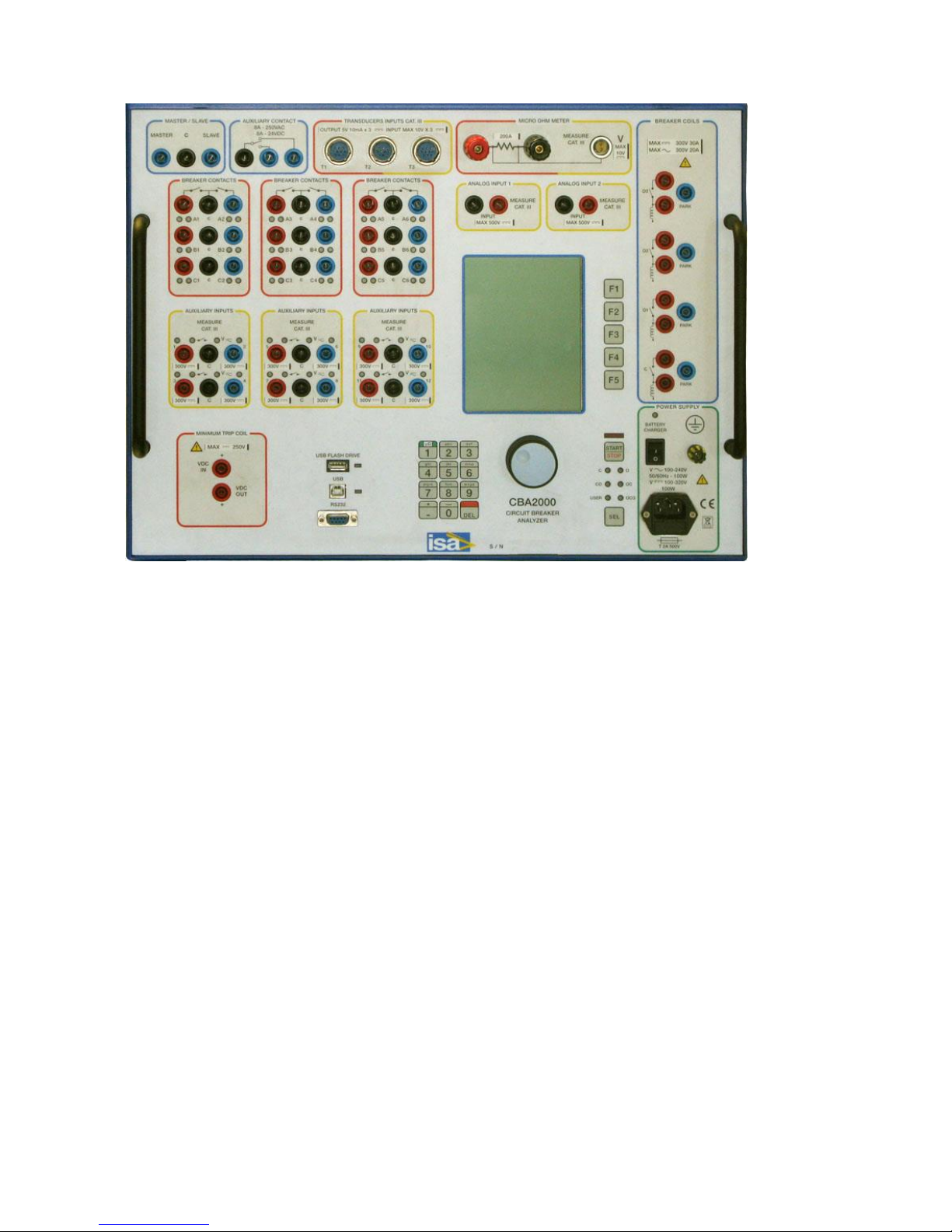
The following is the CBA2000 front panel.
Shop for Power Metering products online at:
1.877.766.5412
www.PowerMeterStore.ca
Page 6
Doc. SIE10169 Rev. 13 Page 7 of 32
NOTE: WINDOWS is a trademark of MICROSOFT inc.
Shop for Power Metering products online at:
1.877.766.5412
www.PowerMeterStore.ca
Page 7

Doc. SIE10169 Rev. 13 Page 8 of 32
2 CHARACTERISTICS
2.1 COIL DRIVING CIRCUITS
. Number of circuits: two; optionally four.
. Type of driver: electronic; it ensures superior timing control.
. Driver characteristic: 300 V DC max; 30 A DC max; 300 V AC max; 20 A AC max.
. Operating time accuracy: 0.025% of delay ± 50 us.
. Coil current ranges: 2.5; 10; 25 A full scale, user selectable.
. The coil current is measured by a dedicated circuit, which is enclosed in the test set, so that a
single connection is enough to connect the coil and to measure its current.
. Number of coil current measurement circuits: two (optionally four ).
. In case of four outputs, it is possible to select the single or multiple phase opening.
. Coil current measurement accuracy: 0.5% of the reading ± 0.1% of the selected range.
. Connection: via four (optionally eight or twelve) safety sockets.
. Outputs are isolated between them.
2.2 MAIN CONTACT INPUTS
. Number of main contact inputs: six in all (two per phase), divided in three groups of two each;
optionally twelve (four per phase), divided in six groups of two each, or 18, divided in 9 groups of
two each.
. Test of the main contact and of the pre-insertion resistor contact, selectable.
. The contact is CLOSED when the contact resistance is less than 10 Ohm.
. Pre-insertion resistor contact range: 20 Ohm to 10 kOhm.
. Contact test voltage: 24 V; test current: 50 mA.
. Each input group is isolated with respect to the others.
. Connection: via nine safety sockets (optionally eighteen or twenty seven safety sockets).
. When a main contact is closed, the corresponding light on the front panel turns on.
2.3 AUXILIARY INPUTS AND OUTPUTS
. Number of auxiliary inputs: four, divided in two groups of two each. Optionally, eight or twelve,
divided in four or six groups of two inputs.
. Each two inputs are isolated with respect to the others.
. Capability of testing dry contacts. Contact test voltage: 24 V; test current: 2 mA.
. Capability of testing wet contacts. Contact input voltage: 20 to 300 V; test current: 2 mA.
. Contact selection can be different on the groups.
. Connection: via six (optionally 12 or 18) safety sockets.
. When an auxiliary input is closed, the corresponding light on the front panel turns on
. One relay auxiliary output. Contact characteristics: 8 A, 250 V DC. The contact operation can be
timed with respect to test start.
Shop for Power Metering products online at:
1.877.766.5412
www.PowerMeterStore.ca
Page 8
Doc. SIE10169 Rev. 13 Page 9 of 32
2.4 INPUTS TIMING
. Sample rate: from 20 kHz maximum, for recording up to 1s to 20 Hz, for recording up to 1s 1000
s. See the table below for more details.
. Resolution: 0.1 ms to 100 ms.
. Inputs timing accuracy: see the following table.
RANGE
FREQUENCY
RESOLUTION
ACCURACY
1 s
20000 Hz
0.1 ms
0.1 ms ± 0.025% of the reading
2 s
10000 Hz
0.2 ms
0.2 ms ± 0.025% of the reading
4 s
5000 Hz
0.4 ms
0.4 ms ± 0.025% of the reading
10 s
2000 Hz
1 ms
1 ms ± 0.025% of the reading
20 s
1000 Hz
2 ms
2 ms ± 0.025% of the reading
40 s
500 Hz
4 ms
4 ms ± 0.025% of the reading
100 s
200 Hz
10 ms
10 ms ± 0.025% of the reading
200 s
100 Hz
20 ms
20 ms ± 0.025% of the reading
400 s
50 Hz
50 ms
50 ms ± 0.025% of the reading
1000 s
20 Hz
100 ms
100 ms ± 0.025% of the reading
2.5 ANALOG INPUT
Number of analog inputs: ten in all, programmable. Common characteristics of analog inputs:
. Measurement resolution: 16 bit.
. Measurement accuracy: 0.5% of the reading ± 0.1% of the selected range.
. Impedance: more than 200 kOhm.
. Measurement sampling rate: 20 kHz max.
2.5.1 Coil currents
The two coil current measurements; optionally four, above described are included in the total of ten
analog channels.
2.5.2 High voltage analog inputs
. Number: two, with no common point.
. Input voltage ranges: ± 5 V; ± 50 V; ± 500 V DC (3.5; 35; 350 V AC), user selected. These ranges
allow measuring all AC and DC voltages.
. Connection: via four safety sockets.
2.5.3 Low voltage analog inputs
. Number: three plus one.
. For all of them, the input voltage range is ± 10 V.
. Three of them are for transducers measurements or for analog input measurements, and have the
same reference point; the fourth one is dedicated to the micro-Ohmmeter.
. For the three inputs, they can be used for position or pressure transducers, or for analog signal
measurements.
Shop for Power Metering products online at:
1.877.766.5412
www.PowerMeterStore.ca
Page 9

Doc. SIE10169 Rev. 13 Page 10 of 32
When used with position transducers, the software allows the displaying of: positions, strokes,
speed (datum point). These measurements are defined by the position of the cursors. In this
instance, it is possible to input the transducer stroke, and to set the unit of measurement as
millimetres, degrees or inches.
When the transducer movement is 50% of the total transducer length, the position error is 1% of the
reading. The error is inversely proportional to the percentage of the transducer movement. When
datum points are 25% of the total transducer length, and the corresponding time is 10 ms, the speed
accuracy is 3%. The error is inversely proportional to the percentage of the transducer movement
and to the movement time.
. When used as analog inputs, the most important use is the monitoring of the secondary current of
an energized CB, to perform the first trip test, that is, the measurement of the Open delay while the
CB is in service. This test is very important to detect the delay caused by the friction, which sticks
the CB that has operated a long time without opening.
. Connection: three via three multi-pole connectors; the fourth one via a two-way shielded
connector.
. On the same connectors is available a polarizing voltage to supply linear position transducers.
. Voltage value: + 5 V; maximum output current 30 mA; minimum transducer resistance 170 Ohm.
The output has the same reference as the three low voltage analog inputs.
2.5.4 Digital transducers
The digital transducer input allows monitoring up to three digital transducers at the meantime.
. Maximum input frequency: 50 kHz;
. Interface: RS422;
. Accepted transducers: up to 5000 impulses per turn.
. Connection: by the same three multi-pole connectors used for the analog inputs.
2.6 TIME MEASUREMENT TRIGGERS
The following time measurement trigger options are user selectable:
. Internal: the time measurement starts as the first Open or Close coil command is issued by the
driving circuit. Timing accuracy: 50 µs.
. Coil current: the time measurement starts as soon as the first Open or Close coil current exceeds
the selected percentage, from 1% to 30%, of the selected current range.
. Auxiliary input: the time measurement starts when the selected auxiliary input turns ON or
changes its state. The trigger can be performed also on a logical combination of auxiliary inputs.
. Analog input: the time measurement starts when the analog input level crosses (greater than, lower
than) the selected threshold.
. External trigger. The test set features a Trigger Out output and a Trigger In input, that allow
synchronizing up to 4 CBA2000’s. In this mode, one CBA2000 acts as the Master unit; its Trigger
Out output will be connected to all other units, selected as Slave. As the Master starts the test, all
other Slave units will measure the timing on Main, auxiliary and analog inputs. Maximum timing
error: 100 us. This feature allows to test circuit breakers with more than two chambers per phase, or
to survey more than four auxiliary inputs, or to survey more than one analog input at a time.
2.7 PROGRAMMABLE SEQUENCES
Shop for Power Metering products online at:
1.877.766.5412
www.PowerMeterStore.ca
Page 10
Doc. SIE10169 Rev. 13 Page 11 of 32
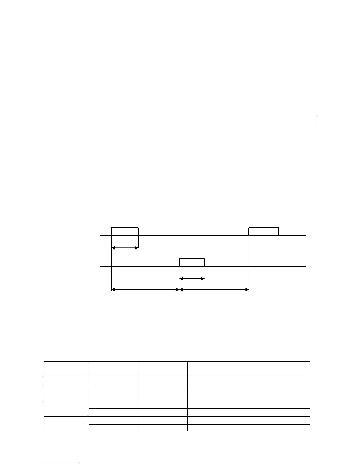
The user can select the following Open and Close sequences:
. Open: the Open coil is driven. In case of four coils, the selected Open coil phase is driven.
. Close: the Close coil is driven.
. OC: In sequence, the Open and Close coils are driven. In case of four coils, the selected Open coil
phase is driven.
. CO: In sequence, the Close and Open coils are driven. In case of four coils, the selected Open coil
phase is driven.
. OCO: In sequence, the Open, the Close and then again the Open coils are driven. In case of four
coils, the first Open command is issued on the selected Open coil phase, while the second Open
command is issued on all coil phases.
Via the software, it is possible to repeat an OC or CO command up to 9999 times.
These sequences are also selected by means of a dedicated pushbutton; the selected sequence is
confirmed by an LED.
For all the above sequences, the user can program the following delays:
. Open command duration: range 10 ms to 10 s.
. Close command duration: range 10 ms to 10 s.
. Open to Close delay: delay range 10 ms to 199.990 s.
. Close to Open delay: delay range 10 ms to 199.990 s.
. Recording duration: range 10 ms to 199.990 s.
. After programming, it is possible to view on the display the sequence timing: this helps avoiding
programming errors.
OPEN
CLOSE
2.8 STATIC RESISTANCE MEASUREMENT (OPTIONAL)
This measurement is performed connecting CBA2000 to the test sample and measuring its
resistance. Test samples can be: joints, main contacts and so on. Main contacts resistance is
measured in the closed position.
. Test current, resistance measuring range, resolution and accuracy: see the table.
TEST
CURRENT
RESISTANCE
RANGE
RESOLUTION
ACCURACY
A
mOhm
μOhm
200
0.2 1 2 % of the reading ± 0.5% of the range
1 1 2 % of the reading ± 0.5% of the range
100
1 1 2 % of the reading ± 0.5% of the range
10 1 1 % of the reading ± 0.3% of the range
20
10 1 1 % of the reading ± 0.3% of the range
100 1 1 % of the reading ± 0.2% of the range
O DURATION
C DURATION
OC DELAY
CO DELAY
Shop for Power Metering products online at:
1.877.766.5412
www.PowerMeterStore.ca
Page 11

Doc. SIE10169 Rev. 13 Page 12 of 32
. Type of current source: electronic constant current generator, driven by a discharging capacitor.
. Current generation duration: minimum 30 ms, according to the test current and the load.
. Capacitor charging time: 60 s.
. Maximum test voltage: 18 V.
. Test mode selection. With single test, the resistance value is displayed. With Circuit Breaker test,
the screen shows a table that collects the measurement of all phases.
. NOTE: during the first 4 ms, the resistance measurement is affected by the connection leads
inductance.
2.9 DYNAMIC RESISTANCE MEASUREMENT (OPTIONAL)
With this measurement it is possible to record the main contact resistance during the CB close.
The CB is open prior to test start: CBA2000 issues the Close command; as the contact closes, the
test current passes through the contact, and CBA1000 measures the contact resistance variations
during the close movement.
. Test current, resistance ranges and other characteristics: as for the static resistance measurement.
. Unlike the static resistance measurement, the test result is not a table of resistance measurements:
it is the resistance profile during the test, along with voltage and current profiles.
2.10 TEST SET CONTROL
. The control is local, via keypad, selectors and display: no PC control is necessary.
. Keypad: 12 keys, numeric plus alphabet: it allows inputting all test references. The arrangement is
the same as portable phones.
. Two dedicated pushbuttons for test start and sequence selection.
. Numeric encoder with pushbutton for menu selection (see below the selections list).
. Five pushbuttons as menu shortcuts
. As the test is started, a buzzer warns the operator.
. The graphical display has the following main features:
- Type: transflective LCD;
- Pixels: 320x 240;
- Backlight color: white;
- View area: 122 x 92 mm;
- Displays: menu selections prior to test start; then, current waveforms, contact inputs (main –
resistance), auxiliary inputs, analog input (those enabled). For dynamic resistance, it is
possible to display the resistance profile, along with voltage and current profiles.
. Memory size: 256 Mbytes (approx. 500 results).
. Maximum record length: 200 s.
. Capability of saving and re-calling up to 64 test settings.
2.11 DATA MANAGEMENT
The communication to the PC can be performed via two communication ports:
. RS232; baud rate 57600;
. USB.
Test results can be saved into an USB pen memory: this allows transferring all test results to the
office without the need of transporting the test set.
Shop for Power Metering products online at:
1.877.766.5412
www.PowerMeterStore.ca
Page 12

Doc. SIE10169 Rev. 13 Page 13 of 32
2.12PC SOFTWARE
The dedicated TDMS software has the following main features.
. Download of test sequences.
. Download of test results.
. Test sequences and test results can be viewed, edited in the missing descriptions, saved, printed,
exported.
. Test data can be organized in a data base including all sub-station devices.
. Possibility of viewing, overlaying and gluing more results, for an easy test result comparison.
. Possibility to pre-set test sequences and to download them into the test set.
. Two cursors to select measurement points and intervals.
. Zoom in and out feature.
. Pass – fail timing test result analysis.
. Pass – fail current profile test result analysis.
. Enhanced measurement features for movement – speed – acceleration control.
The software will be upgraded for free until a new version is released. Upgrading is simple: just
connect to the ISA WEB site, and download the latest version. This applies also to the test set
resident program.
2.13 MENU SELECTIONS
Appendix A lists the features that are menu selected. The menu is operated by means of the MENU
control knob, which incorporates a switch. The menu is entered pressing the knob and selecting the
item moving the knob. Once the item has been found and programmed, pressing the arrow the menu
moves back, so that other programming can be performed.
After test start, measurements are displayed in the corresponding window. Pressing the knob it is
possible to return to menu selections and modify them, and then it is possible to return to the
measurements window.
Any setting can be saved to and recalled from the memory, with a line of text description. At
power-on, the default one is displayed: it can also be recalled as necessary. Settings are permanently
stored in the memory; new settings can be written to the same address after confirmation. For
normal mode operation it is possible to recall the standard setting, that cannot be modified.
During the test, test results can be stored in the memory, according to selections.
Shop for Power Metering products online at:
1.877.766.5412
www.PowerMeterStore.ca
Page 13

Doc. SIE10169 Rev. 13 Page 14 of 32
2.14 OTHER CHARACTERISTICS
. Mains supply:
.. From 85 to 265 V AC; 50-60 Hz,
.. From 100 to 350 V DC.
. Maximum supply current: 1.5 A @ 85 V AC; power consumption 85 VA.
. Test set operation: from the mains, or from an internal battery. Battery characteristics:
.. Type: Ni-Mh, rechargeable.
.. Battery operating time: 4 hours (CB tests); 1 hour (microhmmeter).
.. Battery charging time: 8 hours.
. Housing: aluminium case, with hinged removable cover and handles.
. The instrument comes complete with the following items:
.. Mains cable;
.. User’s manual;
.. Serial cable;
.. USB cable;
.. One cable, yellow/green, for the connection to ground. Cable length: 4 m; cross section 1
sq. mm, terminated with a crocodile;
.. Spare fuses;
.. Software TDMS.
. Dimensions: 485 (W) * 365 (D) * 240 (H) mm.
. Weight: 15 kg.
Shop for Power Metering products online at:
1.877.766.5412
www.PowerMeterStore.ca
Page 14

Doc. SIE10169 Rev. 13 Page 15 of 32
3 OPTIONS
Options 1 to 3 and 5 are to be specified at order, even if it is possible to install them later on.
3.1 STATIC AND DYNAMIC RESISTANCE MEASUREMENT.
The option performances are described at paragraphs 2.8 and 2.9. Physically, it is made of a printed
circuit board, to be mounted on the mother panel, and of a capacitor, to be mounted on the base.
Even if it is possible to upgrade CB2000, it is advisable to request the option at order.
3.2 FOUR COIL COMMANDS.
With this option the test set is provided with the circuits to drive four coils (three Open, one Close),
rather than two. The option is made of an additional printed circuit board that fits into the mother
board.
Even if it is possible to upgrade CBA2000, it is advisable to request the option at order.
3.3 ADDITIONAL MAIN AND AUXILIARY INPUTS.
This option adds to the test set two main contact sensing circuits each phase and four auxiliary
digital event inputs . In this way the instrument has the capability to verify a four chambers breaker
with eight auxiliary digital event inputs.
Optionally, another board could be mounted, in order to have six main contact sensing circuits each
phase (six chambers breaker test) and twelve auxiliary digital event inputs.
3.5 EXTERNAL PRINTER, CODE PII14102.
Thermal printer, for the printout of all test results. Paper 112 mm wide.
3.6 INTERNAL PRINTER.
CBA2000 can be provided with a built-in thermal printer. Printer characteristics:
- Type: thermal;
- Paper width: 58 mm;
- Recordings: the selected window.
This option is exclusive of the DC loss test.
Even if it is possible to upgrade CBA2000, it is advisable to request the option at order:
3.7 MINIMUM TRIP COIL TESTER
The option has the purpose of allowing to test the behaviour of the Minimum Trip Coil circuit and
of Open or Close coils, when supplied at a reduced auxiliary voltage.
There are two modules available: one, code PII34166, is for battery voltages up to 250 V; the other
one, code PII24166, is for battery voltages up to 70 V.
The option is to be connected to the auxiliary DC supply of the plant; the option output voltage can
be modified (stepped or ramped down), according to the test program.
This option is exclusive of the internal printer.
Even if it is possible to upgrade CBA2000, it is advisable to request the option at order.
Shop for Power Metering products online at:
1.877.766.5412
www.PowerMeterStore.ca
Page 15
Doc. SIE10169 Rev. 13 Page 16 of 32
Options characteristics:
OPTION
PII34166
PII24166
Absolute maximum voltage
250 V
70 V
Maximum operating voltage
240 V
50 V
Minimum operating voltage
50 V
16 V
Maximum voltage drop
120 V
45 V
Minimum voltage drop
10 V
5 V
Adjustment step
2 V
0,5 V
Adjustment accuracy
2 V
0,5 V
Maximum output current
4 A; dV < 60 V;
2 A; dV > 60 V
10 A; dV < 12 V;
5 A; dV > 12 V
Maximum test duration
500 ms
500 ms
Pause duration
20 s
20 s
. Connections: one input safety socket, to be connected to the auxiliary supply positive, and one
output safety socket, to be connected to the minimum voltage input.
. Voltage adjustment in steps.
. Over-current protection.
3.8 BASIC CONNECTION CABLES SET; OPTION PII15169
The basic connection cables set includes:
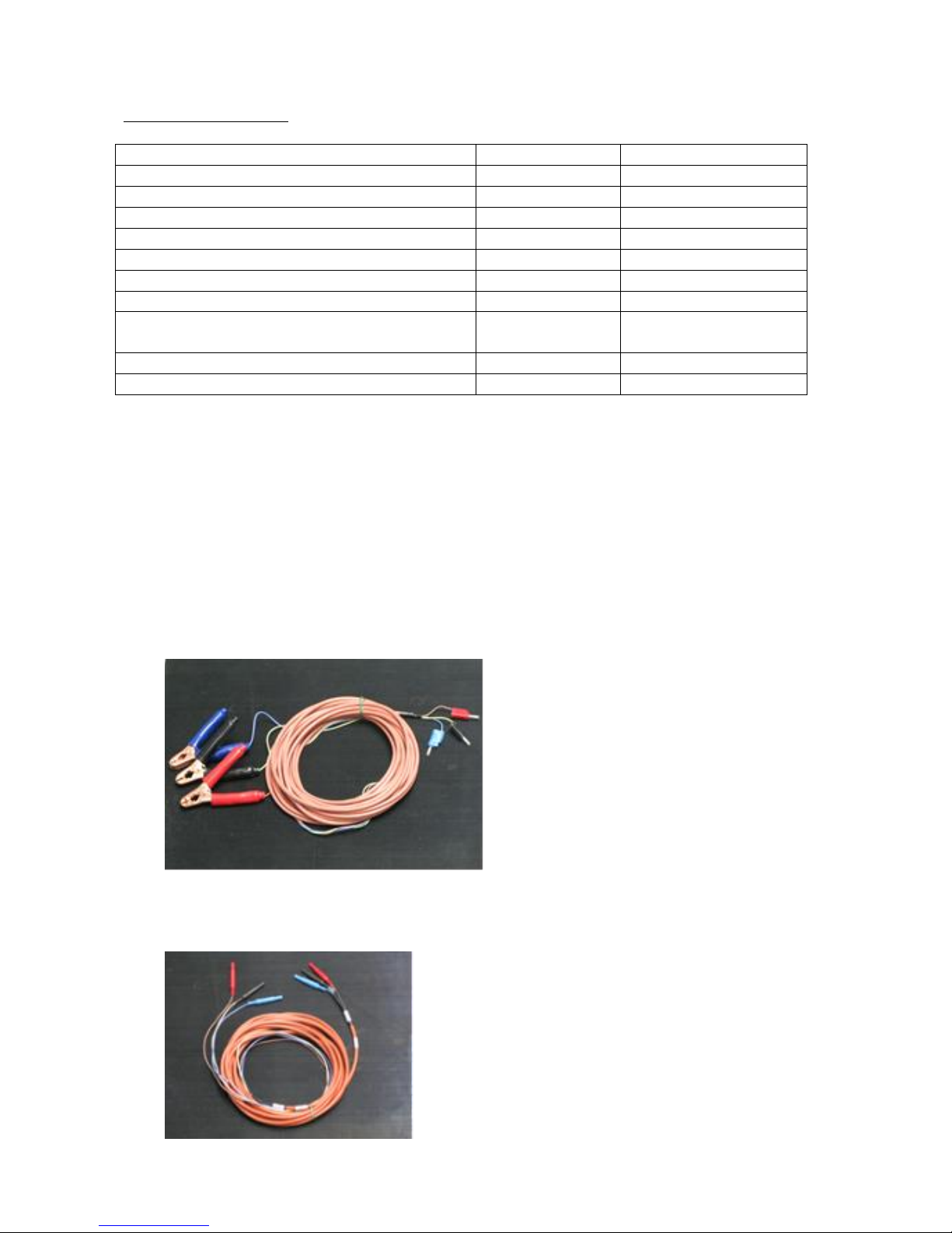
1. Three cables with silicone isolator for the connection to the main contacts, each of three
conductors. Cable length: 16 m; cross section 1 sq. mm. Terminated on the CBA2000 side
with safety banana sockets, with colors: black, red, blue, and on the CB side with three
clamps, with the same colors.
2. Two cables with silicone isolator for the connection to the auxiliary contacts, each of three
conductors. Cable length: 6 m; cross section 1 sq. mm; terminated with safety banana
sockets, with colors: black, red, blue.
Shop for Power Metering products online at:
1.877.766.5412
www.PowerMeterStore.ca
Page 16
Doc. SIE10169 Rev. 13 Page 17 of 32
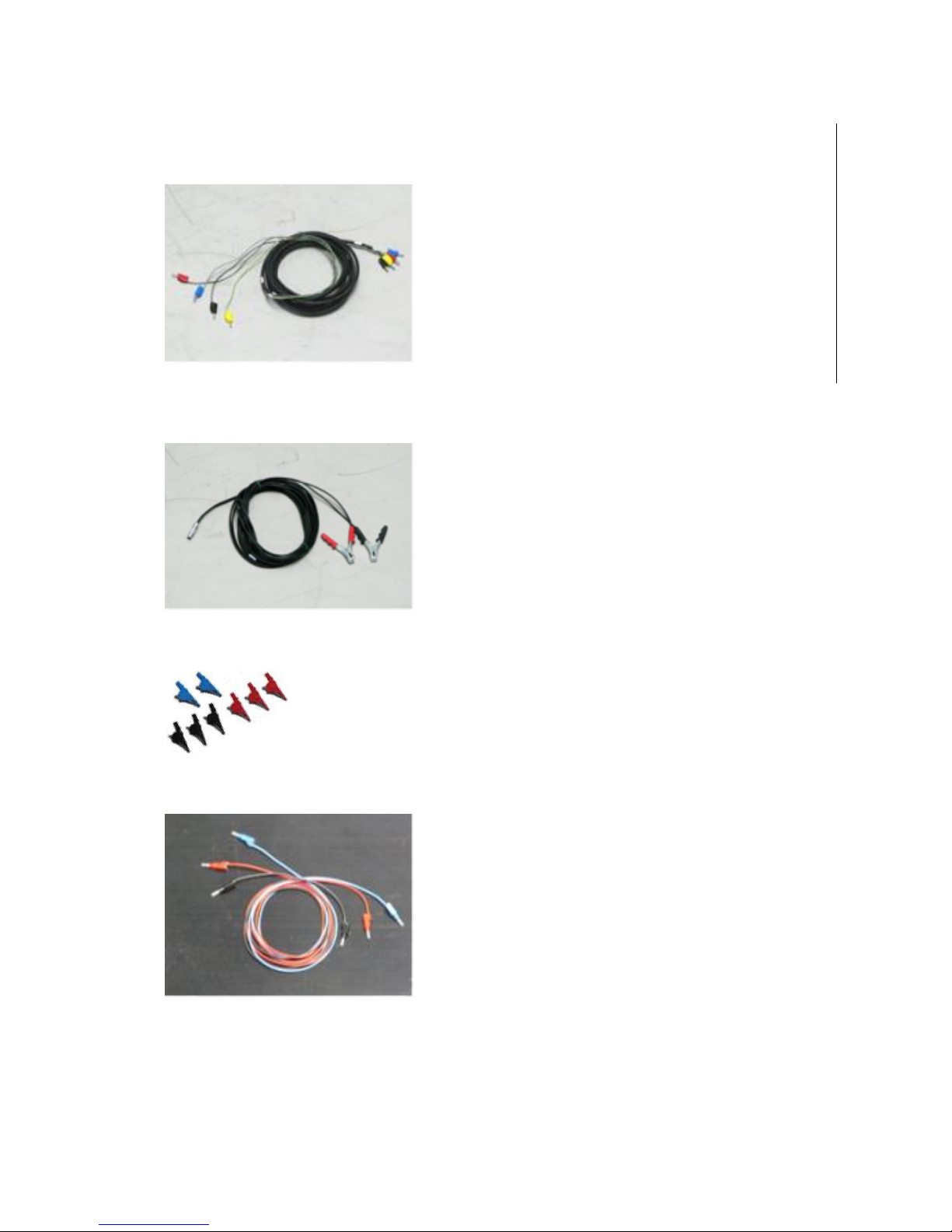
3. Two cables with four conductors each, for the connection to the CB coils. Cable length: 10
m; cross section 1.5 sq. mm, terminated with safety banana sockets; colors: black, red,
yellow, blue.
4. One shielded cable for the measurement of the low voltage, including two conductors.
Cable length: 10 m; cross section 0,5 sq. mm. Terminated with the suitable connector on
the CBA2000 side, and with two clamps on the CB side.
5. One set of crocodiles, 16 in all, with different colors, for the connection to auxiliary
contacts and for the 500 V measurement inputs connection.
6. A set of 12 cables, 2 m long, of different colors, terminated with banana plugs on both
sides, for the connection to other inputs.
7. A set of adaptors from banana sockets to terminators, 20 in all, with different colors, for the
auxiliary contacts and for the coil inputs.
Shop for Power Metering products online at:
1.877.766.5412
www.PowerMeterStore.ca
Page 17
Doc. SIE10169 Rev. 13 Page 18 of 32
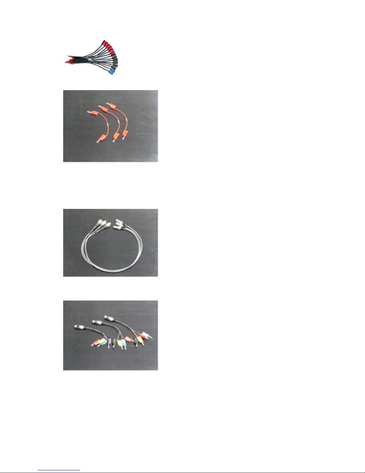
8. Eight short cables, to put in common the coils supply.
9. A cable for the MTC option.
10. Three cables for the connection to analog transducers. Length: 1 m; terminated with a 10way connector on the CBA2000 side, and with a three-way connector on the transducer
side.
11. Three adapters for the connection to analog transducers. Length: 1 m; terminated with a
three-way connector on one side, and with four banana plugs on the other side.
12. Three 10-way cables for the connection to digital transducers. Length 1 m; terminated
with a 10-way connector on the CBA2000 side, and with seven banana sockets on the other
side.
Shop for Power Metering products online at:
1.877.766.5412
www.PowerMeterStore.ca
Page 18
Doc. SIE10169 Rev. 13 Page 19 of 32
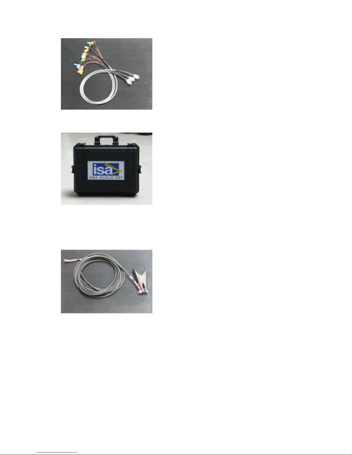
.. One plastic bag that hosts all the cables, with wheels and handles. Dimensions: 45 x 55 x 22
cm.
If the micro-ohm meter option is included, the following connection cables are provided:
.. Two high current cables, made of one conductor. Cable length: 10 m; cross section 25 sq.
mm. Terminated with a suitable terminator on the CBA2000 side, and with an high current
clamp on the CB side.
For each additional main inputs option provided, the following cables are also provided:
.. Three cables with silicone isolator for the connection to the main contacts, each of three
conductors. Cable length: 16 m; cross section 1 sq. mm. Terminated on the CBA2000 side
with safety banana sockets, with colors: black, red, blue, and on the CB side with three
clamps, with the same colors.
.. Two cables with silicone isolator for the connection to the auxiliary contacts, each of three
conductors. Cable length: 6 m; cross section 1 sq. mm; terminated with safety banana
sockets, with colors: black, red, blue. Connection crocodiles are also provided.
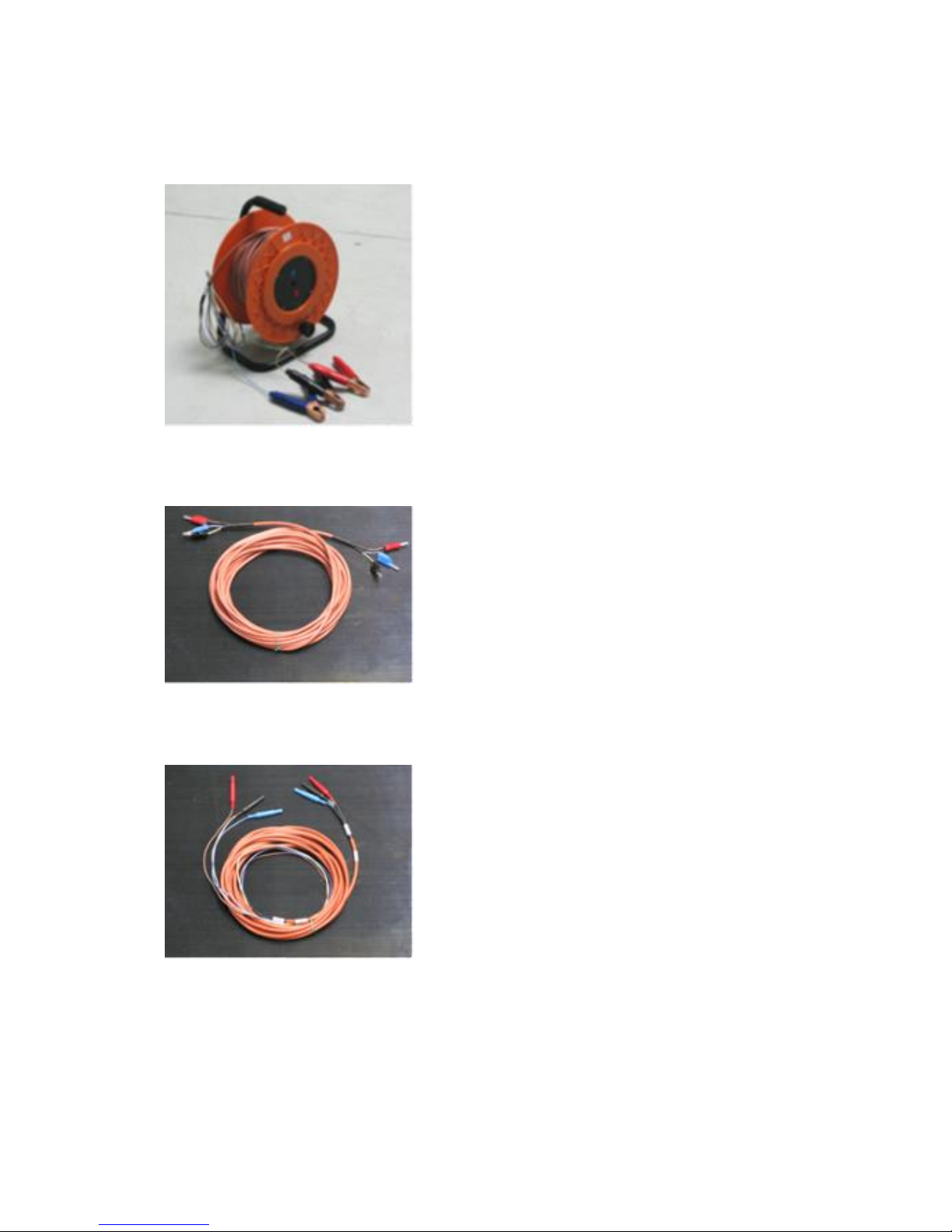
3.9 LONG CONNECTION CABLES; CODE PII81169
The option is the same as above, unless for the items 1 and 2. Instead of them, the option includes:
Shop for Power Metering products online at:
1.877.766.5412
www.PowerMeterStore.ca
Page 19
Doc. SIE10169 Rev. 13 Page 20 of 32
1. Six cables with silicone isolation, 38 m long, cross section 1.5 sq. mm , for the connection
to main contacts, each of three conductors. Each cable is mounted on a support wheel.
Terminated on the CBA2000 side with safety banana plugs, and on the CB side with three
clamps, with different colors.
2. Six cables with silicone isolation, 2 m long, cross section 1.5 sq. mm , for the connection
from CBA2000 to the above wheels.
3. Two cables with silicone isolator for the connection to the auxiliary contacts, each of three
conductors. Cable length: 10 m; cross section 1 sq. mm; terminated with safety banana
sockets, with colors: black, red, blue.
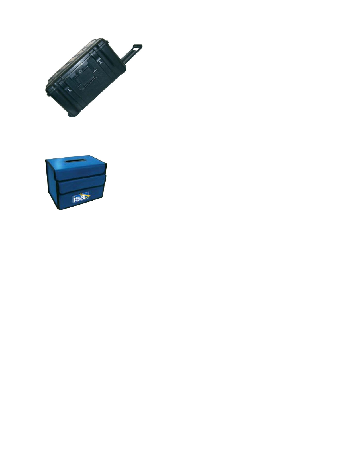
3.10 TRANSIT CASE.
The transit case allows delivering CBA2000 with no concern about shocks up to a fall of 1 m.
Protection degree: IP 65.
Shop for Power Metering products online at:
1.877.766.5412
www.PowerMeterStore.ca
Page 20
Doc. SIE10169 Rev. 13 Page 21 of 32
3.11 SOFT PROTECTION BAG.
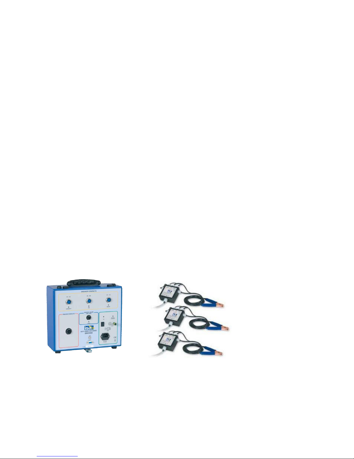
The soft protection bag hosts CBA2000 and protects it against dust and scratches.
3.12 DOUBLE EARTH TESTER BSG1000, CODE PII21166 .
The BSG1000 is an external module, that allows measuring the main contacts timing even if both
ends of the CB are connected to ground, for enhanced safety. The option solves also the problems
of wrong detections when the connection cables are subject to a rather high induced current.
Besides, if the Circuit Breakers has a graphite nozzle, CBA2000 displays the timing at which the
graphite is engaged, and when the main contact is reached, thus allowing to check the deterioration
of the graphite.
The options do not allow to detect the pre-insertion resistance, as it is shunted by the ground
connections.
Available options:
- BSG1000-1, for testing one break per phase (PII21166);
- BSG1000-2, for testing two breaks per phase (PII31166).
Each BSG1000 is made of the following elements:
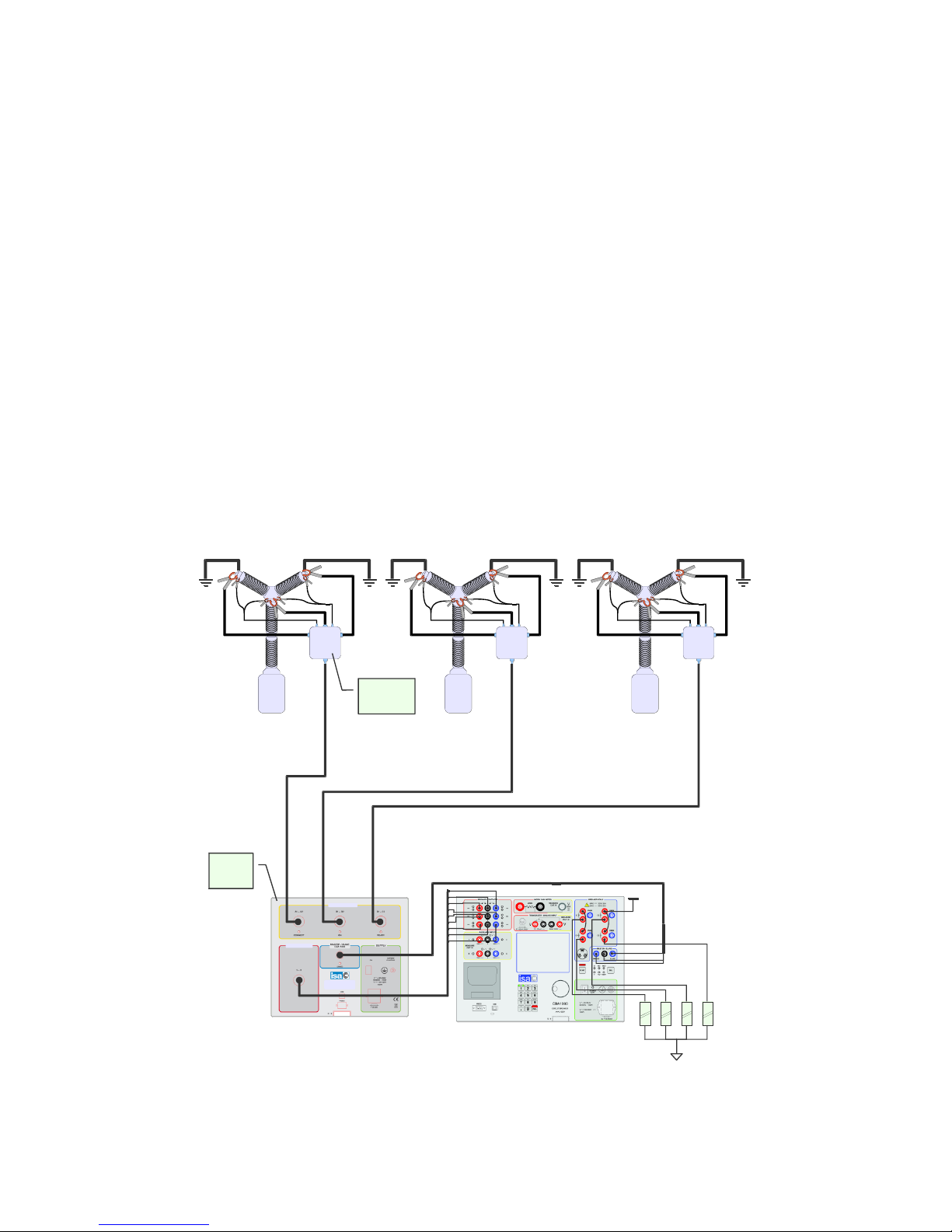
. No 3 BSG Remote Heads, of different types, connected close to the main breaker contacts.
a) Remote Heads for BSG1000- type1 :
. Measurement circuits for one contact;
. Each head has two cables, 2.5 m long, cross section 4 sq. mm, terminated with crocodile clamps,
for the current injection.
. Each head has one bipolar shielded cable, 3 m long, terminated with crocodiles, for the open /
close detection of the CB contacts.
- Each head has one 8 m long cable, terminated with a multi-pole connector, for the connection
between the remote head and the BSG Main unit.
Shop for Power Metering products online at:
1.877.766.5412
www.PowerMeterStore.ca
Page 21
Doc. SIE10169 Rev. 13 Page 22 of 32
b) Remote Heads for BSG1000- type 2 :
. Measurement circuits for two contacts;
. Each head has three cables, 2.5 m long, cross section 4 sq. mm, terminated with crocodile clamps,
for the current injection on two poles.
. Each head has two cables, 2.5 m long, cross section 4 sq. mm, terminated with crocodile clamps,
for the short circuit of noise.
. Each head has two bipolar shielded cable, 3 m long, terminated with crocodiles, for the open /
close detection of the CB contacts.
- Each head has one 8 m long cable, terminated with a multi-pole connector, for the connection
between the remote head and the BSG Main unit.
. No 1 BSG Main unit connected to the CBA2000 breaker analyzer.
. No 1 Cables kit made of:
- N. 1 Nine-way connection cable of BSG Main Unit to CBA1000.
- N. 1 Three-way connection cable for synchronization.
- N. 1 Mains supply cable.
- N. 1 Grounding cable with crocodile.
MAIN UNIT REMOTE HEADS
Option characteristics:
. Number of main contact inputs (type BSG1000-1): 3, divided in three groups.
. Number of main contact inputs (type BSG1000-2): 6, divided in three groups of two each.
. Test current injection: 20 A dc nominal.
Shop for Power Metering products online at:
1.877.766.5412
www.PowerMeterStore.ca
Page 22
Doc. SIE10169 Rev. 13 Page 23 of 32
. Maximum test duration (each test): 1 s.
. Graphite nozzle test selection in the CBA2000 menu. In this instance, the contact with the graphite
is displayed as an intermediate thickness line. The relevant timings are reported.
Mains supply:
.. From 85 to 265 V AC; 50-60 Hz,
.. From 100 to 350 V DC.
. Maximum supply current: 1 A @ 85 V AC.
Weights and dimensions:
BSG1000 main unit
. Housing: aluminium case, with hinged removable cover and handles.
. Weight: 7 kg
. Dimensions: 320 x 180 x 275 (W x H x D)
BSG1000 measuring heads (three units)
. Housing: die-cast aluminium case.
. Weight: 0,7 kg (no cables)
. Dimensions: 125 x 56 x 125 (W x H x D)
The design below refers to the BSG1000-2 type.
1
C O1O1 O1O2 O1O3
+V
BSG
Measuring
Head
CBA1000 CONTACTS
BREAKER CONTACTS
BOTH SIDES GROUNDED
BSG1000
2 3
BSG
Main
Unit
Shop for Power Metering products online at:
1.877.766.5412
www.PowerMeterStore.ca
Page 23
Doc. SIE10169 Rev. 13 Page 24 of 32
3.13 POSITION TRANSDUCERS.
3.13.1 Analog transducers
We have a set of analog transducers, linear and rotating. Linear transducers have different strokes,
and also different IP protections: low for the TLH series, high for the LWG series. A mounting kit
is also available. The table summarizes characteristics and codes.
TYPE
DESCRIPTION
STROKE (mm)
CODE
LINEAR
TLH150
150
PII11166
LINEAR
TLH225
225
PII12166
LINEAR
TLH300
300
PII13666
LINEAR
TLH500
500
PII13166
LINEAR
LWG150
150
PII26166
LINEAR
LWG 225
225
PII27166
LINEAR
LWG 500
500
PII28166
ROTATING - -
PII14166
-
MOUNTING KIT
-
PII16166
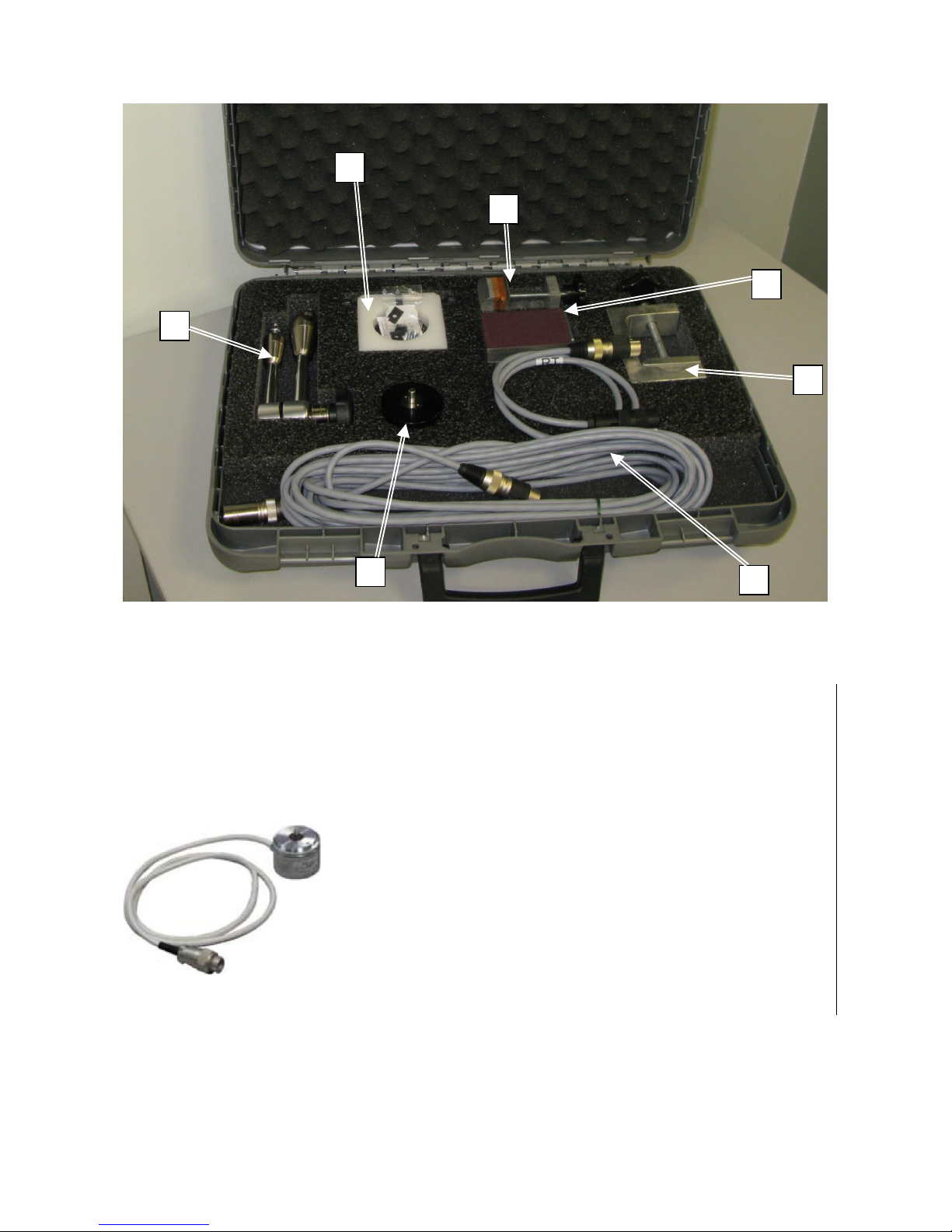
The mounting kit includes the following materials:
. N. 1 Magnetic support (1);
. N. 1 Adaptive arm (2);
. N. 1 Small mechanical clamp (3);
. N. 1 Big mechanical clamp (4);
. N. 1 Support for the rotating transducer (5).
. N. 1 Connection cable (6), 10 m long.
. N. 1 Rotary transducer (7) (or linear transducer, or both).
The kit is included into a plastic transport case. The following picture shows the open case.
Shop for Power Metering products online at:
1.877.766.5412
www.PowerMeterStore.ca
Page 24
Doc. SIE10169 Rev. 13 Page 25 of 32
3.13.2 Digital transducers
The digital transducer option has the following characteristics.
. Transducer name: HENGSTLER RS0-550-170;
. Transducer type: RS422 interface; 5000 impulses per turn;
. Connection: the transducer is connected to the test set via a shielded cable, 10 m long, terminated
with a connector.
Transducer code: PII11169.
Transducer kit code: PII17169.
The mounting kit is the same as above.
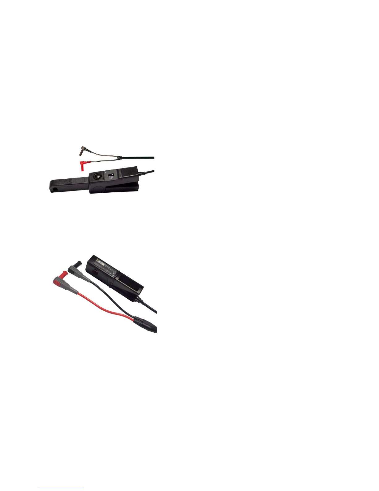
3.14 HALL EFFECT CLIP-ON TRANSFORMER FOR I MEASUREMENTS, CODE PII29166.
The Hall effect clip-on transformer allows measuring the DC current of motors and of the auxiliary
supply. Main characteristics:
. Metering: AC and DC currents.
1 2 3 4 5
6
7
Shop for Power Metering products online at:
1.877.766.5412
www.PowerMeterStore.ca
Page 25
Doc. SIE10169 Rev. 13 Page 26 of 32
. DC measurement null with a knob.
. Ranges: 10 mV/A, 80 A DC, 40 A AC maximum, and 1 V/A, 2 A DC, 1.5 A AC maximum.
. Low battery indicator.
. Measurement errors: 4% of reading + 20 mA for the 80 A range; 2% of reading + 5 mA for the 2
A range.
. Phase shift (up to 65 Hz): maximum 1°.
. Maximum working voltage: 600 V rms.
. Power supply: alkaline 9 V battery, type 6 LR 61.
. Service life: 70 h typical.
. Maximum cable diameter: 10 mm.
. Weight: 330 g.
. Dimensions: 65 mm wide (clamp closed); 36 mm thick; 230 mm long.
3.15 AC CURRENT CLAMP, CODE PII88169.
The current clamp allows performing the first trip test: for three phase testing, three of them are
necessary. The clamp ratio is 1 A//0.1 V; maximum primary current 10 A; maximum cable diameter
12 mm.
3.16 PRESSURE TRANSDUCER, CODE PII13169.
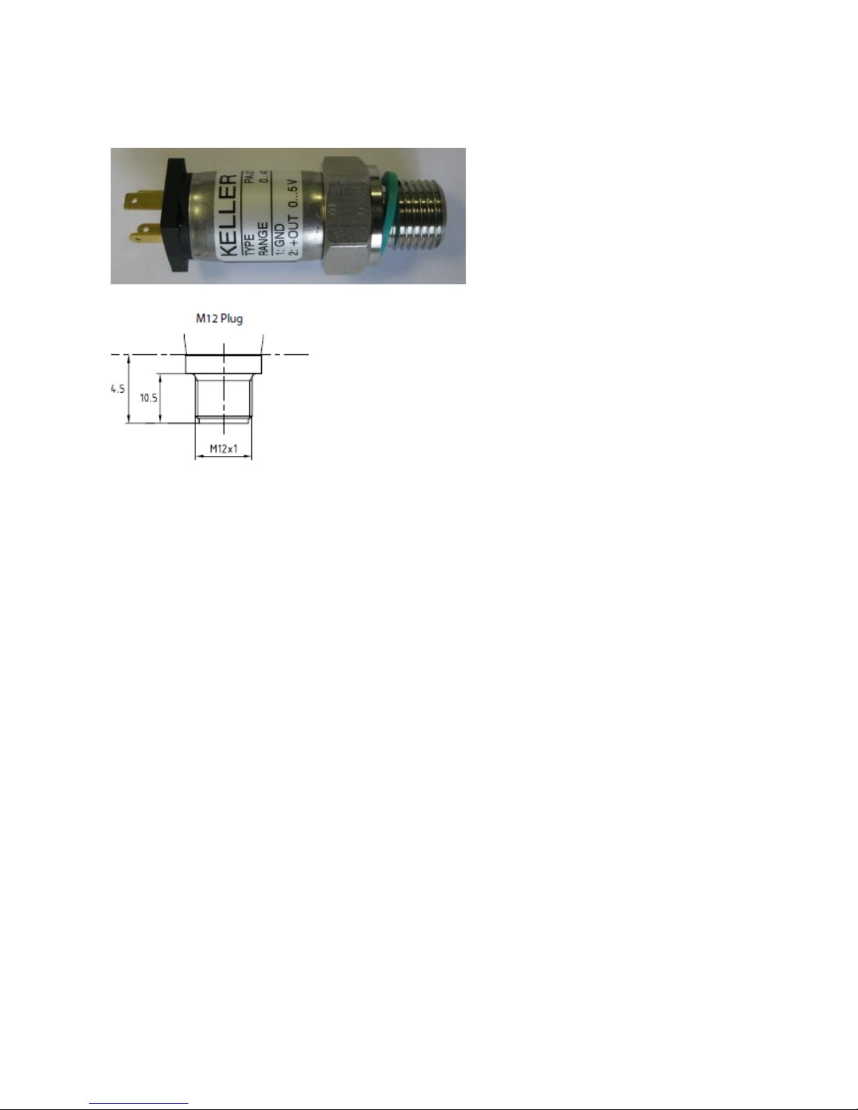
The KELLER pressure transducer type PA-21Y/40bar/81554.33 allows monitoring the variation of
the SF6 pressure while the circuit breaker is operated. Main characteristics:
. Pressure range: 0 to 40 bar (pressure differential with respect to 1 bar of the atmospheric pressure);
. Supply voltage: 8 to 32 V DC;
. Output voltage: 0 to 5 V DC. 0 V at the atmospheric pressure, 5 V at the absolute pressure of 41
bar;
. Linearity error: maximum 0.5% of the range;
. Total error, 0 to 50 °C: maximum 1% of the range;
. Mounting: via an M12 plug, 10.5 mm long;
. Connection to CBA2000: via a 10 m long cable, provided, terminated with the four-poles female
connector on the transducer side, and with the 10 poles male connector on the CBA side;
Shop for Power Metering products online at:
1.877.766.5412
www.PowerMeterStore.ca
Page 26
Doc. SIE10169 Rev. 13 Page 27 of 32
. Once connected, CBA2000 provides the power supply, and the transducer is ready for the
measurement.
Shop for Power Metering products online at:
1.877.766.5412
www.PowerMeterStore.ca
Page 27

Doc. SIE10169 Rev. 13 Page 28 of 32
4 PROTECTIO NS
- Fuse on the mains supply.
- At power-on, a diagnostic sequence controls the microprocessors. If something is wrong, the
operator is alerted by a message.
- The test is started pressing the START pushbutton, and then also pushing the multifunction knob.
- During the test, the circuits driving the coils give alarm messages in case of: selected current range
exceeded (short circuit included); coil driver over-temperature.
- During the test, if the trigger criteria (coil current, auxiliary input, analog input) is not met within
the maximum test time, the test set displays a warning message.
- The 5 V transducer supply is protected against short circuit on the output, and against contact with
a voltage up to ± 500 V. In both instances, the circuit is not damaged.
- All inputs and outputs are isolated between them.
Shop for Power Metering products online at:
1.877.766.5412
www.PowerMeterStore.ca
Page 28
Doc. SIE10169 Rev. 13 Page 29 of 32
APPENDIX A: MENU SEL ECTIONS
LEVEL 1
LEVEL 2
LEVEL 3
LEVEL 4
1 TRIGGER OPTIONS
1 Coil current
% of range (1 to 99)
2 Coil command
3 Coil command
reset
4 Analog input
1 Threshold, positive
or negative
2 input range
5 External trigger on
Slave input
6 Auxiliary input
1 Channel number
2 Logic level: NO,
NC, TRANSITION
3 Logic conditions:
AND, OR
2 TEST OPTIONS
1 Open
A, B, C, AB, BC, CA,
all; *
2 Close
3 Open – Close
4 Close – Open
5 Open – Close –
Open
6 Optional MTC
1 Battery voltage
2 V threshold, %
3 V threshold, V
7 Tolerances
Max trip time
Max close time
Pole discrepancy
open
Pole discrepancy
close
Contact discrepancy
open
Contact discrepancy
close
3 RECORDING
OPTIONS
1 Open coil duration
2 Close coil duration
3 Open to close delay
4 Close to open delay
5 Pretrigger duration
6 Sample frequency
7 Recording duration
8 Two recordings
1 First duration
2 Dead time
3 Second duration
9 Help diagram
Timing diagram
Shop for Power Metering products online at:
1.877.766.5412
www.PowerMeterStore.ca
Page 29
Doc. SIE10169 Rev. 13 Page 30 of 32
LEVEL 1
LEVEL 2
LEVEL 3
LEVEL 4
4 BREAKER AND
AUXILIARY CHANNEL
SETTINGS
1 Breaker contacts
A1;
A1+B1+C1;
all
**
2 Pre-insertion
resistor test
Enable/disable
3 Auxiliary inputs
1-2
**
Enable/disable;
Label;
Dry/wet
4 Auxiliary inputs
3-4
**
Enable/disable;
Label;
Dry/wet
5 ANALOG
CHANNEL/COILS
SETTINGS
1 Close coil range
2.5,10,25 A
2 Open coils range
2.5,10, 25 A
3 Analog input
1 Enabled
2 500 V input range,
label
500,50,5 V DC
3 Travel transducer
Label
Phase
Transducer: U.M.;
Transducer: max
stroke
Supply: 5V int, ext
Breaker: U.M.;
Breaker: stroke;
Nominal transducer
stroke
Travel transducer
calibration
Open position, %
Closed position, %
Actual tr. stroke, %
Tr. stroke error, %
Actual bk. stroke,
%
Bk. stroke error, %
Datum points
definition
Enable
From open to closed
At open position
At closed position
At CB opening
A point set-up
B point set-up
Shop for Power Metering products online at:
1.877.766.5412
www.PowerMeterStore.ca
Page 30
Doc. SIE10169 Rev. 13 Page 31 of 32
LEVEL 1
LEVEL 2
LEVEL 3
LEVEL 4
From closed to open
At open position
At closed position
At CB opening
A point set-up
B point set-up
4 Pressure
transducer
Input: 5 V, 500 V
1 U.M. (Bar, ..)
2 Pressure at zero
voltage
3 Volt per pressure
5 Clip-on transformer
Input: 5 V, 500 V
1 Label
2 I/V ratio
3 Max I
6 MICROOHMMETER
1 Disabled
2 Static contact
resistance
1 Nominal test
current
20, 100, 200 A
2 Resistance range
200µOhm; 1; 10;
100 mOhm
3 Test mode
1 Single
2 Breaker phase
3 Dynamic contact
resistance
1 Nominal test
current
20,100, 200 A
2 Resistance range
200µOhm; 1; 10;
100 mOhm
7 RESULTS
1 Save result
Result name
2 Load result
List of results
3 Delete result
List of results
4 View result
List of results
5 Delete result
List of results
* Only with the four coils option
** More selections if mounted main and auxiliary inputs option(s)
Shop for Power Metering products online at:
1.877.766.5412
www.PowerMeterStore.ca
Page 31
Doc. SIE10169 Rev. 13 Page 32 of 32
LEVEL 1
LEVEL 2
LEVEL 3
LEVEL 4
8 PREFERENCES
1 Date and time
2 Display
1 Contrast
2 Backlight duration
3 Time measurement
ms; 60 Hz cycles; 50
Hz cycles
4 Debounce
ms 5 Buzzer
Yes - No
6 Print diagrams
Yes - No
9 SETUP options
1 Save setup
Name
2 Load setup
List of files
3 Delete setup
List of files
4 Show setup
Name; trigger…
5 Show current setup
Name; trigger…
6 Restore default
10 Tests header
Plant, feeder..
11 Test diagram
Measurements
Results table
Zoom in-out
Function keys
Shop for Power Metering products online at:
1.877.766.5412
www.PowerMeterStore.ca
 Loading...