


RJ-45 Input (Data and Power)
RJ-45 Output (Data Only)
Symbol Description Symbol Description
1
BI_DA+
Data BI_DA+
BI_DA+
Data BI_DA+
2
BI_DA- Data BI_DA- BI_DA- Data BI_DA-
3
BI_DB+
Data BI_DB+
BI_DB+
Data BI_DB+
4
BI_DC+ (Vdc+)
Data BI_DC+ and Feeding power(+)
BI_DC+ Data BI_DC+
5
BI_DC- (Vdc+ )
Data BI_DC- and Feeding power(+)
BI_DC- Data BI_DC-
6
BI_DB-
Data BI_DB-
BI_DB- Data BI_DB-
7
BI_DD+ (Vdc- )
Data BI_DD+ and Feeding power(-)
BI_DD+ Data BI_DD+
8
BI_DD- (Vdc -)
Data BI_DD- and Feeding power(-)
BI_DD- Data BI_DD-
RJ-45 Output (Data and Power) RJ-45 Output (Data Only)
Symbol Description Symbol Description
1 Rx+
Data Receive
Rx+
Data Receive
2
Rx-
Data Receive
Rx-
Data Receive
3
Tx+
Data Transmit
Tx+
Data Transmit
4
Vdc+
Feeding power(+)
NC
Not Connected
5
Vdc+
Feeding power(+)
NC
Not Connected
6
Tx-
Data Transmit
Tx-
Data Transmit
7
Vdc-
Feeding power(-)
NC
Not Connected
8 Vdc-
Feeding power(-)
NC
Not Connected
RJ-45 Input (Data and Power)
RJ-45 Output (Data Only)
Symbol Description Symbol Description
1
BI_DA+ (Vdc+)
Data BI_DA+ and Feeding power(+)
BI_DA+
Data BI_DA+
2
BI_DA- (Vdc+ )
Data BI_DA- and Feedi ng power(+)
BI_DA-
Data BI_DA-
3
BI_DB+ (Vdc-)
Data BI_DB+ and Feeding power(-)
BI_DB+
Data BI_DB+
4
BI_DC+
Data BI_DC+
BI_DC+ Data BI_DC+
5
BI_DC-
Data BI_DC-
BI_DC- Data BI_DC-
6
BI_DB- (Vdc-)
Data BI_DB- and Fee ding power(-)
BI_DB- Data BI_DB-
7
BI_DD+
Data BI_DD+
BI_DD+ Data BI_DD+
8
BI_DD-
Data BI_DD-
BI_DD- Data BI_DD-
RJ-45 Input (Data and Power)
RJ-45 Output (Data Only)
Symbol Description Symbol Description
1 Rx+ (Vdc+)
Data Receive and Feeding power(+)
Rx+
Data Receive
2
Rx- (Vdc+) Data Receive and Feeding power(+) Rx-
Data Receive
3
Tx+ (Vdc-)
Data Transmit and Feeding power(-)
Tx+
Data Transmit
4
NC
Not Connected
NC
Not Connected
5
NC
Not Connected
NC
Not Connected
6
Tx- (Vdc-)
Data Transmit and Feeding power(-)
Tx-
Data Transmit
7
NC
Not Connected
NC
Not Connected
8 NC
Not Connected
NC
Not Connected
Q
uick Start Guide
iPS2 – Industrial Gigabit PoE Splitter
Introduction
Specifications Connector and Pin Definition
The iPS2 is a high power PoE Splitter for use in Power over Ethernet systems. With
Ethernet Input (data + power) port and Output (data only) port, the iPS2 may split
power from existing LAN cable and convert up to 24VDC/1.25A for power hungry
applications such as Wireless APs, Security cameras and IP Phones. The internal
current limit, sho rt-circuit and overload protection are implemented for use as a DC
power supply.
iPS2 Mo del Physical
Ports
10/100/1000 Base-T(X) Ports
PoE Definition 1
1000Base-T
Features
Fully compliant with IEEE802.3at/af standard
Supports 10/100/1000Base-T(X) for PoE In and Data Out
Power Isolation and Sho rt Circuit Protection for Power Output
Auto protection for Over Voltage Power Input
Supports Power Outputs up to 30Watts
in RJ45 Auto MDI/MDI X
1
10/100/1000Base-T(X) P.S.E.
Port in RJ45 Auto M DI/MDIX
1
Operating Voltage
Input Voltage 36 ~ 57 VDC on RJ45 connector
IP-40 Galvanized Steel Case Design
DIN-Rail and wall-mo unt enabled
Output Power
24V @ 1.25A max. (30 Watts)
LED indicators
PWR / Ready: 1 x LED
24V @ 0.45A max. (10.8 Watts)
10/100 Base-T(X)
Connections
Power indicator
Blue On: Power is on and
functioning Normally.
Green On: Power is on and
functioning Normally.
Connections of Splitter
Protection
Short Circuit Protection
Present
Over Load Protection
Present
Isolation Protection
1500V
Physical Characteristi c
Enclosure
IP-40
Note: pi ns 7 and 8 (-Vdc) should not be shorted to ground
Dimension (W x D x H)
26.1(W) x 70(D) x 95(H)mm (1.03x 2.76 x 3.74inch.)
PoE Definition 2
Weight (g)
Environmental
Storage Temperature
250 g
-40 to 80oC (-40 to 176oF)
200 g
1000Base-T
Operating Temperature
-40 to 85oC (-40 to 158oF)
Operating Humidity
5% to 90% Non-condensing
Power Connection Guide
G
Frame Ground
Regulatory Approvals
EMI
EMS
Safety
FCC Part 15, CISPR (EN55022) class A
EN61000-4-2 (ESD),
EN61000-4-3 (RS),
EN61000-4-4 (EF T),
EN61000-4-5 (Surge), EN610004-6 (CS),
EN61000-4-8,
EN61000-4-
11
EN60950-1
10/100 Base-T(X)
V- V- V+ V+ OUT PUT DC 24V
Warranty
5
years
Power
Output
24 VDC
Note: pi ns 3 and 6 (-Vdc) should not be shorted to ground
QSG
1
8
1
8
1
8
1
8
Quick Start Guide
iPS2 – Industrial Gigabit PoE Splitter
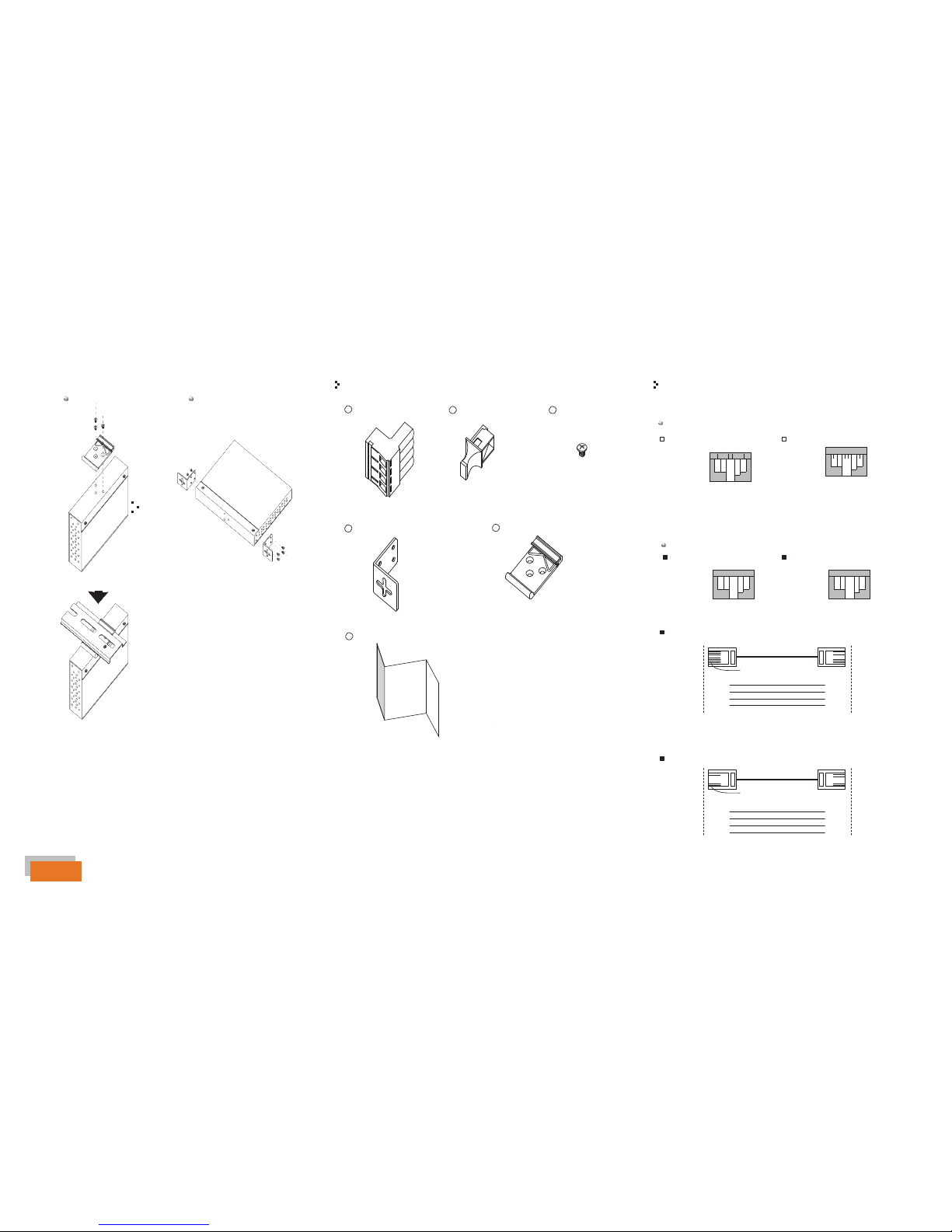
Installation
Din-Rail Install Step Wall-mounted Install Step
Accessories
Communication Connections
1
4-Pin Terminal block
2
Dust Cover (RJ-45)
3
Screw (M3 X3)
1000Base-T Ethernet Port Connection
RJ45 (8-pin, MDI) Port Pinouts
RJ45 (8-pin, MDI-X) Port Pinouts
Pin
1
2
3
4
5
6
7
8
MDI
BI_DA+
BI_DABI_DB+
BI_DC+
BI_DCBI_DBBI_DD+
BI_DD-
PPi
n
1
2
3
4
5
6
7
8
MDI-X
BI_DB+
BI_DBBI_DA+
BI_DD+
BI_DDBI_DABI_DC+
BI_DC-
4
Wall-mounted kit
5
25mm DIN-Rail kit
10/100Base-T(X) Ethernet Port Connection
RJ45 (8-pin, MDI) Port Pinouts RJ45 (8-pin, MDI-X) Port Pinouts
Pin
Single
Pin Single
1
Tx+
2
Tx-
3
Rx+
6 Rx-
1
Rx+
2
Rx-
3
Tx+
6 Tx-
6
QIG
RJ45 (8-pin) to RJ45 (8-Pin) Straight-Through Cable Wiring
Switch Port
Straight-Through Cable
NIC Port
RJ-45
Connector
Tx+
TxRx+
Rx-
RJ45 Plug Pin1
3
6
1
2
RJ-45
Connector
3 Rx+
6 Rx-
1 Tx+
2 Tx-
RJ45 (8-pin) to RJ45 (8-Pin) Cross-Over Cable Wiring
Switch Port
(NIC Port)
RJ-45
Connector
Cross-Over Cable
RJ45 Plug Pin1
Switch Port
(NIC Port)
RJ-45
Connector
(Rx+) Tx+ 3 1 Rx+ (Tx+)
(Rx-)
(Tx+)
(Tx-)
Tx- 6
Rx+ 1
Rx- 2
2 Rx-
3
Tx+
6 Tx-
(Tx-)
(Rx+)
(Rx-)
Q I G
#3-7490 Pacific Circle, Mississauga, Ontario, L5T 2A3
Support: 1 (905) 670 - 0004
QSG
 Loading...