


Intelligent Flexible Secure Gateway
IEC 61850-3 and IEEE 1613 compliant
iSG4F User’s Manual
Version 1.1
September 2014
iS5 Communications Inc.
#3-7490 Pacific Circle
Mississauga, Ontario, L5T 2A3
Tel: + 905 670 0004
Fax: + 289 401 5201
Website: www.iS5Com.com
E-mail: support@iS5Com.com

iSG4F User’s Manual
2
COPYRIGHT NOTICE
Copyright © 2013 iS5 Communications Inc.
All rights reserved.
No part of this publication may be reproduced in any form without the prior written consent of
iS5 Communications Inc. (iS5).
TRADEMARKS
iS5Com is a registered trademark of iS5. All other trademarks belong to their respective owners.
REGULATORY COMPLIANCE STATEMENT
Product(s) associated with this publication complies/comply with all applicable regulations.
Please refer to the Technical Specifications section for more details.
WARRANTY
iS5 warrants that all products are free from defects in material and workmanship for a specified
warranty period from the invoice date (5 years for most products). iS5 will repair or replace
products found to be defective within this warranty period including shipping costs. This
warranty does not cover product modifications or repairs done by persons other than
iS5-approved personnel, and this warranty does not apply to products that are misused,
abused, improperly installed, or damaged by accident.
Please refer to the Technical Specifications section for the actual warranty period(s) of the
product(s) associated with this publication.
DISCLAIMER
Information in this publication is intended to be accurate. iS5 shall not be responsible for its use
or infringements on third-parties as a result of its use. There may occasionally be
unintentional errors on this publication. iS5 reserves the right to revise the contents of this
publication without notice.
CONTACT INFORMATION
iS5 Communications Inc.
#3-7490 Pacific Circle, Mississauga, Ontario, L5T 2A3
Tel: + 905-670-0004 // Fax: + 289-401-5206
Technical Support E-mail: support@iS5Com.com
Sales Contact E-mail: sales@iS5Com.com
Website: www.iS5Com.com
iS5 Communications Inc.

3
Table of Content
iSG4F User’s Manual
CAUTION: LASER
CAUTION: SERVICE
CAUTION: PHYSICAL ACCESS
......................................................................................... 9
..................................................................................... 9
..................................................................... 9
Getting to Know Your Router ......................................................................10
1.1 About the iSG4F Intelligent Flexible Secure Gateway ................................................................ 10
1.2 Software Features ............................................................................................................................... 10
1.3 Hardware Features ............................................................................................................................. 10
Hardware Overview ...................................................................................... 11
2.1 Front Panel .......................................................................................................................................... 11
2.2 Rear ....................................................................................................................................................... 12
2.3 Bottom ................................................................................................................................................. 12
2.4 Side view .............................................................................................................................................. 12
2.5 Logical System Diagram ................................................................................................................... 13
Hardware Installation ................................................................................... 13
3.1 DIN Rail Mounting ........................................................................................................................... 13
3.2 Panel Mounting Option .................................................................................................................... 14
3.3 Chassis Ground Connection ............................................................................................................ 14
3.4 Power Connections ............................................................................................................................ 15
3.5 Console Connection .......................................................................................................................... 16
Configuration ............................................................................................... 16
5.1 Command Line Interface .................................................................................................................. 16
5.2 Supported Functionalities ................................................................................................................. 17
5.3 System Default State .......................................................................................................................... 18
5.4 Main Commands ................................................................................................................................ 18
System Version and Data Base ................................................................... 19
6.1 Configuration Database .................................................................................................................... 19
6.2 OS VERSION .................................................................................................................................... 20
6.3 Commands Hierarchy ........................................................................................................................ 20
6.4 OS Upgrade Example........................................................................................................................ 21
6.5 Safe Mode ............................................................................................................................................ 23
iS5 Communications Inc.

iSG4F User’s Manual
4
6.5.1 Safe Mode View .................................................................................................................................. 23
6.5.2 SW Image Installation ....................................................................................................................... 25
Ethernet Port Interfaces .............................................................................. 27
7.1 Commands Hierarchy ........................................................................................................................ 28
7.2 Port Commands Example ................................................................................................................ 28
Login and Management ............................................................................... 30
8.1 Serial Console Port .......................................................................................................... 30
8.1.1 Connecting to the Console Port ....................................................................................... 30
8.1.2 CLI Terminal Commands ................................................................................................ 31
8.2 Management .................................................................................................................... 31
8.2.1 Default state .................................................................................................................... 31
8.2.2 Commands Hierarchy ...................................................................................................... 31
8.2.3 Commands Description ................................................................................................... 32
IP Interfaces .................................................................................................. 33
9.1 IP Interfaces .................................................................................................................... 33
9.1.1 Interface Assignment Rules .............................................................................................. 34
9.1.2 IP interface id .................................................................................................................. 35
9.1.3 IP interface VLAN id ....................................................................................................... 35
9.1.4 IP Interface Commands Hierarchy ................................................................................... 35
9.1.5 IP Interface Commands Description ................................................................................ 36
9.1.6 IP Interface Example ....................................................................................................... 36
9.1.7 DHCP Example............................................................................................................... 39
Diagnostic..................................................................................................... 40
10.1 System logs export ........................................................................................................... 40
10.1.1 Commands Hierarchy ...................................................................................................... 40
10.1.2 Commands Description ................................................................................................... 40
10.2 Capture Ethernet service traffic ....................................................................................... 40
10.2.1 Commands Hierarchy ...................................................................................................... 41
10.2.2 Commands Description ................................................................................................... 41
10.2.3 Example .......................................................................................................................... 42
10.3 Syslog .............................................................................................................................. 43
10.3.1 Syslog Priority indicator ................................................................................................... 43
10.3.2 Syslog Commands Hierarchy ............................................................................................ 44
10.3.3 Syslog Output example .................................................................................................... 44
Alarm Relay .................................................................................................. 45
11.1 Alarm Relay Wiring example ............................................................................................ 45
iS5 Communications Inc.

iSG4F User’s Manual
5
11.2 Alarm Relay Contact Capabilities ..................................................................................... 46
11.3 Supported Alarms ............................................................................................................ 46
11.3.1 SFP port state .................................................................................................................. 46
11.3.2 L2 VPN state ................................................................................................................... 46
11.3.3 System up/down .............................................................................................................. 46
11.4 Default state .................................................................................................................... 46
11.5 Commands Hierarchy ...................................................................................................... 46
11.6 Commands Description ................................................................................................... 47
Clock and Time ............................................................................................ 48
12.1 Local Clock Commands Hierarchy ................................................................................... 48
12.2 Local Clock Commands Description ................................................................................ 49
12.3 Set Local Clock Example ................................................................................................. 49
ACLs ............................................................................................................. 49
13.1 ACL Commands Hierarchy .............................................................................................. 50
13.2 ACL Commands Descriptions ......................................................................................... 50
13.3 Configuration Example .................................................................................................... 53
QOS ............................................................................................................... 53
14.1 QOS Commands Hierarchy ............................................................................................. 53
14.2 QOS Commands Descriptions ......................................................................................... 53
NAT ................................................................................................................ 54
15.1 NAT Networking ............................................................................................................. 54
15.2 NAT Commands Hierarchy ............................................................................................. 55
15.3 NAT Commands Description .......................................................................................... 56
15.4 NAT Example ................................................................................................................. 56
OSPF ............................................................................................................. 59
16.1 OSPF Application Commands Hierarchy ......................................................................... 59
16.2 OSPF Application Commands Descriptions .................................................................... 59
16.3 OSPF setup example ........................................................................................................ 60
RIPv2 ............................................................................................................. 66
17.1 RIP Commands Hierarchy ............................................................................................... 66
17.2 RIP Commands Descriptions ........................................................................................... 67
Serial Ports and Services ............................................................................ 68
18.1 Serial interfaces ................................................................................................................ 69
18.2 Services configuration structure ....................................................................................... 69
iS5 Communications Inc.

iSG4F User’s Manual
6
18.3 Serial Commands Hierarchy ............................................................................................. 70
18.4 Serial Commands Description .......................................................................................... 71
18.5 Declaration of ports ........................................................................................................ 74
18.6 Serial Port Default State ................................................................................................... 75
18.7 RS- 232 Port Pin Assignment ........................................................................................... 75
18.8 RS- 232 Serial cable .......................................................................................................... 76
18.9 Led States ........................................................................................................................ 76
Transparent Serial Tunneling ...................................................................... 77
19.1 Concept of Operation ..................................................................................................... 77
19.2 Supported Network Topologies ....................................................................................... 78
19.2.1 Point to Point .................................................................................................................. 78
19.2.2 Point to multipoint point ................................................................................................. 78
19.2.3 Multi Point to multipoint point ........................................................................................ 79
19.3 Modes of Operation ........................................................................................................ 79
19.3.1 Port Mode ....................................................................................................................... 80
19.3.2 Service Buffer Mode ........................................................................................................ 80
19.3.3 Service Connection Mode ................................................................................................ 81
19.4 Addressing Aware Modes ................................................................................................. 81
19.5 Reference drawing ............................................................................................................ 82
19.6 Serial Traffic Direction ..................................................................................................... 83
19.6.1 Serial ports counters ........................................................................................................ 83
19.7 Allowed Latency .............................................................................................................. 84
19.8 Tx Delay .......................................................................................................................... 84
19.9 Bus Idle Time .................................................................................................................. 84
19.9.1 Byte mode ....................................................................................................................... 84
19.9.2 Frame mode..................................................................................................................... 84
19.10 Example Serial Tunneling................................................................................................. 85
Protocol Gateway IEC 101 to IEC 104 ........................................................ 86
20.1 Modes of Operation ........................................................................................................ 87
20.2 IEC101/104 Gateway properties IEC 101 ....................................................................... 88
20.3 IEC101/104 Gateway Configuration ................................................................................ 89
20.4 Gateway 101/104 Configuration Flow ............................................................................. 90
20.5 Gateway 101/104 Commands Hierarchy .......................................................................... 92
20.6 Gateway 101/104 Commands .......................................................................................... 93
20.7 Example Gateway 101/104 .............................................................................................. 96
Terminal Server ............................................................................................ 98
21.1 Terminal Server service .................................................................................................... 98
iS5 Communications Inc.

iSG4F User’s Manual
7
21.2 Terminal Server Commands Hierarchy ........................................................................... 100
21.3 Terminal Server Commands ........................................................................................... 101
21.4 Example local Service .................................................................................................... 107
21.5 Example Networking ..................................................................................................... 111
Modbus Gateway ....................................................................................... 113
22.1 Modbus Gateway Implementation ................................................................................. 113
22.2 Modbus Gateway Commands Hierarchy ........................................................................ 113
22.3 Modbus Gateway Commands Description ..................................................................... 115
22.4 Modbus Gateway Example ............................................................................................ 116
DNP3 Gateway ............................................................................................ 119
23.1 DNP3 Gateway Example ............................................................................................... 119
VPN ............................................................................................................. 120
24.1 Background ................................................................................................................... 120
24.2 Modes supported ........................................................................................................... 120
24.3 Layer 2 VPN .................................................................................................................. 120
24.4 Layer 3 DM-VPN .......................................................................................................... 121
24.5 L2-VPN Commands Hierarchy ...................................................................................... 121
24.6 L2-VPN Commands ...................................................................................................... 122
24.7 L3 DM-VPN Commands Hierarchy ............................................................................... 122
24.8 L3 IPSec-VPN Commands Hierarchy ............................................................................ 123
24.9 IPSec ............................................................................................................................. 124
24.10 Applications ................................................................................................................... 124
24.11 Authentication Header (AH) .......................................................................................... 124
24.12 Encapsulating Security Payload (ESP) ............................................................................ 124
24.13 Security Associations...................................................................................................... 124
24.14 ISAKMP ........................................................................................................................ 125
24.15 IKE ............................................................................................................................... 125
24.15.1 ISAKMP Phase 1 ........................................................................................................... 125
24.15.2 ISAKMP Phase 2 ........................................................................................................... 132
24.16 IPSec Command Association ......................................................................................... 133
24.17 IPSec Commands Hierarchy .......................................................................................... 134
24.18 IPsec Commands ........................................................................................................... 136
24.19 IPSec defaults ................................................................................................................ 142
GPRS/UMTS Interface ................................................................................ 142
25.1 Overview ....................................................................................................................... 142
25.2 Method of operation ..................................................................................................... 143
iS5 Communications Inc.

iSG4F User’s Manual
8
25.2.1 SIM card state ................................................................................................................ 144
25.2.2 Backup and redundancy ................................................................................................. 146
25.3 GPRS/UMTS Commands Hierarchy ............................................................................. 147
25.4 GPRS/UMTS Commands Description .......................................................................... 148
25.5 Default State .................................................................................................................. 152
25.6 Led States ...................................................................................................................... 152
25.7 Example for retrieving the IMEI .................................................................................... 152
25.8 Example for SIM Status ................................................................................................. 153
VPN Setup Examples ................................................................................. 154
26.1 L2 VPN over Layer 3 cloud ........................................................................................... 154
26.1.1 Network drawing ........................................................................................................... 154
26.1.2 Configuration................................................................................................................. 154
26.1.3 Implementing IPSec ....................................................................................................... 157
26.2 L3 IPSec VPN over Layer 3 cloud .................................................................................. 157
26.2.1 Network drawing ........................................................................................................... 158
26.2.2 Configuration................................................................................................................. 158
26.3 DM-VPN Setup ............................................................................................................. 163
26.3.1 Network drawing ........................................................................................................... 163
26.3.2 Configuration................................................................................................................. 164
26.4 DM-VPN over Cellular Setup ........................................................................................ 167
26.4.1 Network drawing ........................................................................................................... 168
26.4.2 Configuration................................................................................................................. 169
26.4.3 Testing the setup ............................................................................................................ 172
26.4.4 Adding a terminal server service .................................................................................... 175
26.4.5 Adding a transparent serial tunneling service .................................................................. 176
Application Aware Firewall........................................................................ 177
27.1 Firewall Service Flow ..................................................................................................... 177
27.2 Firewall Flow Illustration ............................................................................................... 178
27.3 Supported Hardware ...................................................................................................... 178
27.4 Configuration................................................................................................................. 178
27.5 Example ........................................................................................................................ 179
27.6 Firewall Commands Hierarchy ....................................................................................... 180
27.7 Firewall Commands ....................................................................................................... 180
Technical Specifications ........................................................................... 182
iS5 Communications Inc.

iSG4F User’s Manual
9
FCC Statement and Cautions
Federal Communications Commission Radio Frequency Interference Statement
This equipment has been tested and found to comply with the limits for a Class A digital device
pursuant to Part 15 of the FCC Rules. These limits are designed to provide reasonable protection
against harmful interference when the equipment is operated in a commercial environment.
This equipment can generate, use, and radiate radio frequency energy. If not installed and used in
accordance with the instruction manual, may cause harmful interference to radio
communications. Operation of this equipment in a residential area is likely to cause harmful
interference in which case the user will at his/her own expense, be required to correct the
interference.
Caution: LASER
This product contains a laser system and is classified as a CLASS 1 LASER PRODUCT. Use of controls
or adjustments or performance of procedures other than those specified herein may result in
hazardous radiation exposure.
Caution: Service
This product contains no user-serviceable parts. Attempted service by unauthorized personnel shall
render all warranties null and void.
Changes or modifications not expressly approved by iS5 Communications Inc. could invalidate
specifications, test results, and agency approvals, and void the user's authority to operate the
equipment.
Should this device require service, please contact support@iS5Com.com.
Caution: Physical Access
This product should be installed in a restricted access location. Access should only be gained by qualified
service personnel or users who have been instructed on the reasons for the restrictions applied at the
location, and any precautions that have been taken. Access must only be via the use of a tool or lock
and key, or other means of security, and is controlled by the authority responsible for the location.
iS5 Communications Inc.

iSG4F User’s Manual
10
Getting to Know Your Router
1.1 About the iSG4F Intelligent Flexible Secure Gateway
The iSG4F Flexible Secure Gateway is designed for use in remote sites that require secure remote
connections over a public network (via serial or IP connection). A serial RTU/IED connected to an
iSG4F would communicate its data over a landline or a cellular public/private connection for those
sites that are remotely distributed and connected to a SCADA control center. The user data can
either be transparently encapsulated over an IP tunnel, or converted to an IP SCADA session using
the integrated SCADA gateway. Network connectivity is secured using a Layer 2 or Layer 3 VPN
with IPSec, as well a SCADA firewall for validating all traffic to the device. The iSG4F can be
managed centrally and conveniently by our powerful Windows utility called the iManage Software
Suite. The product is made from galvanized steel and has a wide operating temperature from -40°C
to 85°C suitable for the harshest of environments without the use of fans.
1.2 Software Features
Layer 2 and Layer 3 VPN with IPSec
SCADA firewall for validating all traffic to the device
Supports Layer 3 protection
Supports Gateway Translation for IES 101, IEC 104, Modbus and DNP3
ACL (Access Control Lists)
NAT (Network Address Translation)
OSPF (Open Shortest Path First) protocol
RIPv2 (Routing Information Protocol)
Transparent Serial Tunneling
Terminal Server service for transposing of a TCP session to serial session
Modbus RTU to Modbus TCP
GPRS/UMTS Interface
1.3 Hardware Features
Network Uplink over Ethernet or Cellular
Supports 2 x RS232 ports, or 1 x RS232 and 1x RS485 port (RJ45 sockets)
Supports 1x 10/100 Base (TX) and 1 x 1000 Base (X) Ethernet Ports
Supports 2 SIM Cellular Interfaces for connecting to remote sites over a cellular network
Console Port
Dual Redundant Power Input
Wide Operating Temperature: -40 to 85
iS5 Communications Inc.
o
C

iSG4F User’s Manual
11
Port
Description
Console
RJ45, EIA232 VT-100 compatible port
E1
Ethernet Port 1, 1 X 10/100/1000 Base- T(X) RJ45 port
E2
Ethernet Port 2, 1 x 100/1000Base-X on SFP port (SFP located on
bottom side)
S1, S2
Serial port 1 and Serial port 2, RS232 Serial RJ45 Ports
Optional: 1 X RS232 Serial RJ45 Port and 1 X RS485 Serial RJ45 Port
Cellular
Dual SIM GPRS/UMTS
Storage Temperature: -40 to 85
Operating Humidity: 5% to 95%, non-condensing
DIN Rail or Wall mount option
Chassis: IP-40 Galvanized Steel
Dimensions(W x D x H) : 127 mm(W)x 163.6 mm( D )x 154.2 mm(H) (5 in x 6.44 in x 6.07 in)
o
C
Hardware Overview
2.1 Front Panel
Product description:
iS5 Communications Inc.

iSG4F User’s Manual
12
2.2 Rear
The image below shows the DIN bracket on the back of the router. Circled in red are the mounting holes
for the Panel bracket mounting option.
2.3 Bottom
The image below shows the 10 position terminal block and ground lug of the iSG4F.
2.4 Side view
The image below shows the side of the iSG4F with the product label displaying router information. Circled
in red are the side mounting holes for the Panel bracket mounting option.
iS5 Communications Inc.

13
2.5 Logical System Diagram
iSG4F User’s Manual
Hardware Installation
3.1 DIN Rail Mounting
Each router has a DIN-Rail bracket on the rear panel that allows the router to be mounted on
a DIN Rail. To mount the iSG4F on a DIN Rail follow the steps below.
1. Slant the top of the router back and hook the top of the DIN bracket onto the top of the
DIN rail.
2. Push the bottom of the router towards the DIN Rail until in clicks in to place.
iS5 Communications Inc.

14
Note: To release the router from the DIN Rail, pull the latch at the bottom of the router down
to release the DIN bracket from the DIN Rail. While pulling the latch down, pull the bottom of
the router away from the DIN Rail. The router will now lift off of the DIN rail.
3.2 Panel Mounting Option
The router can also has an option to be panel or wall mounted. The following steps show how
to mount the router on a panel or wall.
1. Install the Panel mounting hardware onto the router. The user can choose rear mounting
or side mounting. Note: To avoid damage to the unit please use the 4 screws provided to
attach the panel mount brackets onto the router.
iSG4F User’s Manual
2. Use the holes in the brackets to secure the router to a wall or panel.
3.3 Chassis Ground Connection
The iSG4F chassis ground connection uses a #6-32 Screw. We recommend terminating the ground
connection using a #6 ring lug, and a torque setting of 15 in.lbs (1.7Nm). The red outline indicates the
location of the chassis ground.
iS5 Communications Inc.

iSG4F User’s Manual
15
Terminal
Number
Description
Connection
1
- PWR1 (+/L) – Line or Positive
- PWR1 (+): Positive
Connected to the line or positive
terminal of the first power source.
2
- PWR1 – Ground
Power supply 1 ground connection.
3
- PWR1 (-/N) – Neutral or Negative
- PWR1 (-) : Negative
Connected to the neutral or negative
terminal of the first power source.
4
– Chassis Ground
Connected to the safety ground terminal
for AC units or the ground bus for DC
inputs. Chassis ground connects to both
power supply surge grounds via a
removable jumper.
5
- PWR2 (+/L) – Line or Positive
Connected to the line or positive
3.4 Power Connections
The iSG4F router supports dual redundant power supplies (PWR1 and PWR2). There are 3 options for
each power supply:
1. LV: Dual Input 10-48VDC
2. MV: Dual Input 36-75VDC
3. HV: Single Input 85-264VAC or 88-370VDC.
The label on the terminal block will indicate the accepted voltage range for PWR1 and PWR2. Positions 2,
4 and 6 are all for ground connections (connected via a removable jumper) and can be used for any ground
connection.
The Phillips Screw Terminal Block has Phillips screws with compression plates, allowing either bare wire
connections or crimped terminal lugs. The use of #6 size ring lugs is recommended to ensure secure and
reliable connections under severe shock or vibration. The terminal block comes with a safety cover which
must be removed before connecting any wires. This cover must be re-attached after wiring to ensure
personnel safety.
The table below lists the connections for the terminal block.
iS5 Communications Inc.
iSG4F User’s Manual
16
- PWR2 (+): Positive
terminal of the second power source.
6
- PWR2 – Ground
Power supply 2 ground connection.
7
- PWR2 (-/N) – Neutral or Negative
- PWR2 (-) : Negative
Connected to the neutral or negative
terminal of the second power source.
8
RLY NO
Failsafe relay, normally open contact.
9
RLY CM
Failsafe relay, common contact.
10
N/C
No connection
100-240VAC rated equipment: A 250VAC appropriately rated circuit
breaker must be installed.
Equipment must be installed according to the applicable country wiring
codes.
When equipped with a HI voltage power supply and DC backup,
88-300VDC rated equipment: A 300VDC appropriately rated circuit breaker
must be installed.
A circuit breaker is not required for DC power supply voltages of 10-48VDC.
For Dual DC power supplies, separate circuit breakers must be installed and
separately identified.
Equipment must be installed according to the applicable country wiring
3.5 Console Connection
To manage the router via the console port, connect the console cable (provided with the iSG4F) from a PC
serial port (DB9) to the Console port on the front of the router (RJ45).
Configuration
5.1 Command Line Interface
iS5 Communications Inc.
The CLI (Command Line Interface) is used to configure the iSG4F from a console attached to
the serial port of the router or from a remote terminal using SSH. The following table lists the
CLI environments and modes.

iSG4F User’s Manual
17
Command Mode
Access Method
Prompt
Exit Method
Global
Configuration
Environment
(GCE)
Following user log in this
mode is available to the user.
iSG4F#
To exit this mode
would mean the user
to log out from the
system.
Use the command
‘exit’
Global Hierarchy
Configuration
From the Global
Configuration mode
command you may drill down
to specific feature sub tree.
Example is shown here for
router configuration sub tree.
router/
To exit one level back,
the ‘..’ (Two dots) is
used.
Application
Configuration
Environment
(ACE)
The ACE is an alternative
configuration environment for
supported features
ACE#
To exit back to the GCE
mode use the ‘exit’
command.
ACE Config
Use the command ‘configure’
to access the ACE
Configuration mode
ACE(config)#
To exit back to the ACE
mode use the ‘exit’
command.
Application
Hierarchy
Configuration
Access the target feature. For
example :
‘interface vlan 1’
ACE(config-if-eth1.1)#
To return one level up
use ‘exit’.
To return to the ACE
use ‘end’.
5.2 Supported Functionalities
iS5 Communications Inc.
The iSG4F is a feature rich industrial router supporting:
L3 dynamic and static Routing
SCADA services
Firewall
Secure networking
Supported features include:
Ethernet Ports
Serial Ports
Cellular Modem
VPN
TFTP
OSPF

iSG4F User’s Manual
18
Feature
Default state
Ethernet Ports
All ports are enabled
Serial interfaces
Disabled
Cellular modem
Disabled
Layer 3 interface
No default IP
DHCP Client
disabled
SSH
Disabled
Telnet
Enabled
Syslog
Disabled
ACLs
Disabled
Firewall
Disabled
VPN
Disabled
Vlan Tagging
IPSec
Management
Authentication
5.3 System Default State
The following table details the default state of features and interfaces.
SCADA Gateway
SCADA Firewall
QOS
Serial Services
Terminal Services
NAT
RIP
DHCP Client
5.4 Main Commands
The Application Configuration Environment list of main CLI commands is shown below.
+ root
+ Router {interface | route |static |ospf |ip |rip}
+ cellular {connection | continuous-echo| disable |enable| modem|
network| refresh| settings| show| wan}
+ commit
+ capture {delete |export |help |show |start |stop}
+ date
+ discrete {service| show}
+ dns {host| resolver}
+ exit
+ firewall {log| profile| tcp| serial}
iS5 Communications Inc.

iSG4F User’s Manual
19
+ idle-timeout
+ iec101-gw {cnt| operation| config iec-101| config iec-104| config
gw| show}
+ ipsec {enable| disable| isakmp update| policy| preshared| log-show| show|
show-sa proto}
+ ipsec-vpn tunnel {show | create | remove}
+ vpn {gre| ipsec| l2}
+ ping
+ reload {cancel| schedule| show}
+ schedule {add |show |remove}
+ serial {card |port| local-end-point| remote-end-point}
+ ssh
+ syslog show
+ telnet
+ terminal-server {admin-status| counters| settings| connections| serial-tunnel|
telnet-service}
+ trace
+ version
System Version and Data Base
6.1 Configuration Database
By default User configuration is saved in a file called iSG4F.conf. Configuration saved in this
file will be available at system startup. If this file is deleted, the system will boot with the
iSG4Fnvram.txt file holding factory configuration.
User Configuration is taking effect immediately upon entering. No specific COMMIT command
is required.
The user can as well save his running configuration in a file with a chosen name for backup
and boot the system with this file when needed.
Multiple running configuration files can be saved with different names locally on the flash or
a TFTP /SFTP server.
However, configuration which will not be saved as bellow example will not be available
following system reboot.
User configuration is saved (to the iSG4F.conf) using the following command:
iSG4F# commit
iS5 Communications Inc.

iSG4F User’s Manual
20
NOTE
iSG4F.conf and iSG4Fnvram.txt files are not accessible for the user to do file
operations on (copy ,rename and such)
NOTE
The iSG4F can hold at its disk maximum two OS image files. Before
downloading a new OS file to the router make sure the iSG4F has on it only one
(the active) file. If needed, delete the unused file before attempting to
download new.
Building configuration...
[OK]
Removing all user configuration and setting the router to its factory defaults is done by
erasing the iSG4F.conf with the following command:
iSG4F# delete startup-cfg
iSG4F# reload
6.2 OS VERSION
Updating of system version is available by TFTP/SFTP server or safe mode.
Available OS files on the router can be seen with command showed below.
Running OS file is marked with “active”.
iSG4F#os-image show-list
Versions list:
IS5_iSG4F_4.0.02.08.tar (active)
6.3 Commands Hierarchy
+ Root
- commit
+ delete
iS5 Communications Inc.
- diagnostics
- logs

21
- startup-cfg
- os-image show-list
- os-image activate version-name <file_name>
- os-image delete version-name <file_name>
- os-image download-sw sftp://user:password@aa.bb.cc.dd/file_name
- os-image download-sw tftp://aa.bb.cc.dd/file_name
- os-image download-status
- Reload
- db import {remote-host <IP, A.B.C.D>} [filename <>]
- db export {remote-host <IP, A.B.C.D>} [filename <>]
- show disk info
6.4 OS Upgrade Example
iSG4F User’s Manual
The following flow will show how to upgrade the OS image file and export the data base.
1. Connect your PC via serial console cable to the iSG4F console port.
2. Create an IP interface over eth1.
iSG4F#router interface create address-prefix 172.18.212.231/24
physical-interface eth1 purpose application-host
3. Check connectivity to the TFTP server from which the software will be downloaded.
PING 172.18.212.240 (172.18.212.240): 56 data bytes
64 bytes from 172.18.212.240: seq=0 ttl=64 time=1.026 ms
64 bytes from 172.18.212.240: seq=1 ttl=64 time=0.642 ms
64 bytes from 172.18.212.240: seq=2 ttl=64 time=0.647 ms
4. Display available OS files.
iS5 Communications Inc.

iSG4F User’s Manual
22
iSG4F# os-image show-list
Versions list:
IS5_iSG4F_4.0.02.07.tar (active)
IS5_iSG4F_4.0.02.06.tar
5. Delete unneeded OS files.
iSG4F# os-image delete version-name IS5_iSG4F_4.0.02.06.tar
iSG4F# os-image show-list
Versions list:
IS5_iSG4F_4.0.02.07.tar (active)
iSG4F#
6. Download OS file from TFTP server.
Command syntax:
iSG4F# os-image download download tftp://aa.bb.cc.dd/file_name
Example:
os-image download download-sw
tftp://172.18.212.240/IS5_iSG4F_4.0.02.09.tar
7. Following download progress.
iSG4F#os-image download-status
In progress 3 MB
iSG4F#os-image download-status
In progress 10 MB
iSG4F#os-image download-status
In progress 16 MB
iSG4F#os-image download-status
Finished Download
8. Activating desired OS file (will automatically reboot the device).
iSG4F# os-image activate version-name IS5_iSG4F_4.0.02.09.tar
..
iSG4F# os-image show-list
iS5 Communications Inc.

23
Versions list:
IS5_iSG4F_4.0.02.07.tar
IS5_iSG4F_4.0.02.09.tar (active)
9. Exporting configuration data base to TFTP server.
Command syntax:
iSG4F# db export filename my-file-name remote-host aa.bb.cc.dd
Example:
iSG4F# db export filename db-May-14 remote-host 172.18.212.240
6.5 Safe Mode
The system has two safe mode menus available.
iSG4F User’s Manual
To access safe mode, connect to the router via console cable, reboot the unit and interrupt
the boot process at the safe mode prompt.
The first Safe mode is for use by approved technicians only and should not be used unless
specified by iS5 Communications. This safe mode state is available at the prompt:
“For first safe mode Press 's'...”
The second safe mode is accessible at the following prompt:
##########################
For safe mode Press 's'...
##########################
The screenshot in Safe Mode View details the 2 safe mode menus and their options for:
1. system reset
2. Loading the factory-default configuration for the device
3. Writing to the EEPROM (should be used only after consulting with iS5 Communications)
4. Recovering the device's images from a package file
5. Export / Import DB (running configuration)
6.5.1 Safe Mode View
For first safe mode Press 's'...
PHY: fixed-0:02 - Link is Up - 100/Full
s
iS5 Communications Inc.

iSG4F User’s Manual
24
-------------------------------------------------------------------------------
----------
|safe mode menu: |
| reset | 1 : Reset the device |
| format | 2 : Format flash |
| activate | 3 : Activate sw version on flash |
| install | 4 : Install first sw version from TFTP |
| continue | c : Continue with start up process |
| help | H : Display help about this utility |
c
Extracting software
\s
OK
01/01/70 00:01:09 Running applications
##########################
For safe mode Press 's'...
##########################
-------------------------------------------------------------------------------
----------
|safe mode menu:
| reset | 1 : Reset the device
| defcfg | 2 : Load the factory-default configuration for the device
| eeprom | 3 : Write to EEPROM
| recover | 4 : Recover the device's images from a package file
| db | 5 : Export / Import DB
| continue | c : Continue in start up process
| help | H : Display help about this utility
iS5 Communications Inc.

25
6.5.2 SW Image Installation
The Following steps are for the first software installation.
1. Connect your PC via serial console cable to the iSG4F console port.
2. Reboot the unit and Enter first safe mode. Select option 4.
-------------------------------------------------------------------------------
----------
|safe mode menu: |
| reset | 1 : Reset the device |
| format | 2 : Format flash |
| activate | 3 : Activate sw version on flash |
| install | 4 : Install first sw version from TFTP |
| continue | c : Continue with start up process |
iSG4F User’s Manual
| help | H : Display help about this utility |
!!!!!!!!!!!!!!!!!!!!!!!!!!!!!!!!!!!!!!!!!!!!!!!!!!!!!!!!!!!!!!!!!!!!!!!!!!!!!!!
!!!!!!!!!!
!!!!!!!!!!!!!!!!!!!!!!!!! This choice will delete data from flash
!!!!!!!!!!!!!!!!!!!!!!!
!!!!!!!!!!!!!!!!!!!!!!!!! Continue [y/n]
!!!!!!!!!!!!!!!!!!!!!!!
!!!!!!!!!!!!!!!!!!!!!!!!!!!!!!!!!!!!!!!!!!!!!!!!!!!!!!!!!!!!!!!!!!!!!!!!!!!!!!!
!!!!!!!!!!
y
3. Assign IP address and subnet to the iSG4F.
!!!!!!!!!!!!!!!!!!!!!!!!!!!!!!!!!!!!!!!!!!!!!!!!!!!!!!!!!!!!!!!!!!!!!!
!!!!!!!!!!!!!
! Connect an ethernet cable to the ETH port and Enter the following parameters
(xxx.xxx.xxx.xxx) !
!!!!!!!!!!!!!!!!!!!!!!!!!!!!!!!!!!!!!!!!!!!!!!!!!!!!!!!!!!!!!!!!!!!!!!
!!!!!!!!!!!!!
DEVICE IP ADDRESS [10.10.10.5]: [enter an IP for the iSG4F]
DEVICE IP ADDRESS NETMASK [255.255.255.0]: [enter subnet ip for the iSG4F]
iS5 Communications Inc.

iSG4F User’s Manual
26
4. Choose the interface at which the telnet server is connected to the iSG4F.
Select Interface (press 1 or 2)[1]:
1) ETH1 10/100 MB
2) ETH2
1
5. Set the IP address of the TFTP server holding the OS-Image file
TFTP SERVER IP ADDRESS [10.10.10.10]: 10.10.10.6
6. Connect the iSG4F at port ETH1 (RJ45) to your tftp server.
Verify ping availability between the two.
7. Enter the OS-image file name.
Enter version number on TFTP Server.
For main menu press X
IS5_iSG4F_4.0.02.08.tar
iS5 Communications Inc.

iSG4F User’s Manual
27
8. OS-Image file will be downloaded and activated.
01/01/70 00:03:18 downloading IS5_iSG4F_4.0.02.08.tar from server
10.10.10.6 to /opt/iS5com,try #1
============25%===========50%===========75%=75%===========100%Version
Download Complete
OEM Ver IS5_iSG4F
OEM NEW_VERSION IS5_iSG4F_4.0.02.03.tar
Detected OEM 3
Veryfing sw version IS5_iSG4F_4.0.02.03.tar
=appl.tar.gz: OK
==vmlinux.UBoot: OK
SW version was verified successfully
vmlinux.tar
=vmlinux.UBoot: OK
Updating bank1 with vmlinux.UBoot file, please wait ...===OK
Version was installed and activated successfully
Reboot in 0=
Ethernet Port Interfaces
The iSG4F hardware includes the following Ethernet interfaces:
Gigabit Ethernet, copper RJ45.
Copper 10/100/1000 Base T(X) supported.
Referred to in CLI as eth1.
Gigabit Ethernet, SFP SGMII.
Copper and fiber SFP of 100/1000 Base X are supported.
Referred to in CLI as eth2.
SFP modules are not included.
iS5 Communications Inc.

28
7.1 Commands Hierarchy
+ root
+ port
- set port { eth1| eth2} [admin-status {disabled |enabled}]
[autoneg {on| off}] [duplex {half| full} [speed {10| 100|
1000}]
+ show
- interface-table port-type port {eth1| eth2}
- rmon-etherstat-table port {eth1| eth2}
- status
+ sf-port
- ddm
- detailed
- extended
iSG4F User’s Manual
7.2 Port Commands Example
iSG4F# port show interface-table port eth1
Interface ETH1
+------------------------+--------+-------------------------+-------+
| Counter Name | Value | Counter Name | Value |
+========================+========+=========================+=======+
| In non-unicast packets | 2670 | Out non-unicast packets | 5 |
+------------------------+--------+-------------------------+-------+
| In unicast packets | 233 | Out unicast packets | 4 |
+------------------------+--------+-------------------------+-------+
| In errors packets | 0 | Out errors packets | 0 |
+------------------------+--------+-------------------------+-------+
| In octets | 311651 | Out octets | 690 |
+------------------------+--------+-------------------------+-------+
| Unknown packets | 0 | | |
+------------------------+--------+-------------------------+-------+
iS5 Communications Inc.

iSG4F User’s Manual
29
iSG4F# port show status
+-----+------+------+--------------+------------------+-------+-------
-+
| idx | slot | port | admin Status | auto Negotiation | speed | duplex |
+=====+======+======+==============+==================+=======+=======
=+
| 1 | 1 | eth1 | enabled | on | 100M | full |
+-----+------+------+--------------+------------------+-------+-------
-+
| 2 | 1 | eth2 | enabled | on | 100M | full |
+-----+------+------+--------------+------------------+-------+-------
-+
iSG4F# port show rmon-etherstat-table port eth1
Interface ETH1
+---------------+--------+----------------+-------+
| Counter Name | Value | Counter Name | Value |
+===============+========+================+=======+
| total packets | 2789 | undersize | 0 |
+---------------+--------+----------------+-------+
| total octets | 300591 | oversize | 0 |
+---------------+--------+----------------+-------+
| broadcast | 1832 | Size 64 | 1055 |
+---------------+--------+----------------+-------+
| multicast | 725 | Size 65-127 | 1239 |
+---------------+--------+----------------+-------+
| align error | 0 | Size 128-255 | 435 |
+---------------+--------+----------------+-------+
| dropped event | 0 | Size 256-511 | 35 |
+---------------+--------+----------------+-------+
| fragmented | 0 | Size 512-1023 | 4 |
+---------------+--------+----------------+-------+
iS5 Communications Inc.

30
| jabbers | 0 | Size 1024-1518 | 21 |
NOTE
A console cable is supplied in the box.
RJ45 Male
DB9 Female
1 - 2
3
+---------------+--------+----------------+-------+
Login and Management
Configuring the Login Authentication Method sets the authentication method for user logins.
Default user of the system:
Name : su
Password : 1234
Privileges : all
Available by: Console and Telnet.
iSG4F User’s Manual
8.1 Serial Console Port
Management over the serial console port is enabled by default.
8.1.1 Connecting to the Console Port
The console port is an EIA232 VT-100 compatible port to enable the definition of the device's
basic operational parameters.
Connecting the device to a PC using the Console Port:
Connect the RJ-45 connector of the console cable to the device's Console Port (CON).
Connect the other side of the cable to the PC.
Configure the PC port to 9600-N-8-1 (9600 bps, no parity, 8 data bits, 1 stop bit, no flow
control).
Below table details the console cable pinout.
iS5 Communications Inc.

31
3 2 4 5 5 5 6 - 7 - 8
-
Feature
Default state
Layer 3 interface
No default IP
SSH
No available
Telnet
Enabled
Console
Enabled
User
User name : su
Password : 1234
Privilege : all
DHCP Client
disabled
8.1.2 CLI Terminal Commands
Following are commands related to the CLI terminal.
+ root
- idle-timeout
iSG4F User’s Manual
8.2 Management
The router can be managed via following methods:
IP based
Serial console port
8.2.1 Default state
8.2.2 Commands Hierarchy
+ root
+ reload
- schedule date-and-time YYYY-MM-DD,HH:MM:SS
- schedule every <180 – 604800 seconds >
- schedule time HH:MM:SS
- schedule in <0 – 604800 seconds >
iS5 Communications Inc.

iSG4F User’s Manual
32
Command
Description
Application Connect
reload schedule
date-and-time
Set specific date and time for router reload.
Time format: YYYY-MM-DD,HH:MM:SS
Note: configuration which was not committed will
not be available after reload!
reload schedule every
Set time interval for cyclic automatic system
reload.
Permissible range in seconds is 180 – 604800.
Note: Configuration which was not committed will
not be available after reload!
reload schedule time
Set specific time for router reload.
Time format: HH:MM:SS
Note: configuration which was not committed will
not be available after reload!
- cancel
- show
- commit
- delete diagnostics
- delete logs
- delete startup-cfg
- show disk info
- router interface show
- ping <destination>
- ssh {<user>@<remote IP>}
- telnet [user]@{remote IP}
8.2.3 Commands Description
iS5 Communications Inc.

iSG4F User’s Manual
33
Command
Description
reload schedule in
Set specific timer for next router reload.
Permissible range in seconds is 180 – 604800.
Note: Configuration which was not committed will
not be available after reload!
reload cancel
Cancels all scheduled automatic reloads.
reload show
Shows user scheduled reloads.
IP Interfaces
The iSG4F supports multiple layer 3 interfaces to be set for the purposes of:
Routing
Management
Serial services
9.1 IP Interfaces
The following services require assignment of an IP interface:
DHCP client
Management
Ping
Trace route
OSPF
RIPv2
Tftp client
iS5 Communications Inc.
Serial tunneling
Terminal server
Protocol gateway

34
L2-VPN
L3-DMVPN
IPSec
9.1.1 Interface Assignment Rules
- An IP interface may optionally be set with a VLAN tag to result in VLAN tagging at the interface
egress.
- The VLAN tag set to an interface must be unique.
- If a VLAN tag is not set, packets will carry no VLAN tag when they egress the interface.
- An interface id is automatically assigned to each IP interface.
- Each interface must be associated with a “purpose”.
iSG4F User’s Manual
One (and only one) of the interfaces must be set to purpose ‘application-host’
All other interfaces must be set to purpose ‘general’
If a “purpose” is not configured by the user, the interface will receive the ‘general’ status.
- Each interface must be in a unique subnet.
- Each interface must be associated to a physical interface. Either eth1 or eth2.
An interface cannot be associated with both.
- Physical interfaces (eth1, eth2) may be associated with more than one IP interface. Tagged
packets accessing the port will be routable to a relevant VLAN IP interface. Untagged packets
accessing the port will be routable with an IP interface set to be in the same subnet as the
packets origin (if such is available on the iSG4F).
- IP interfaces associated to VLANs are given an automatic name indicating the VLAN tag they
are created with. The name format is:
eth<1|2>.<vlan id>
- IP interfaces not associated to a VLAN, are given an automatic name indicating the id they are
created with. The name format is:
eth<1|2>:<id>
- Below is an example of interfaces configured with either VLAN tag or id tag.
- [/]router interface show
- +----+------+---------+-------------------+------+------------------+--------------+-------------+
- | Id | VLAN | Name | IP/Subnet | Mtu | Purpose | Admin status | Description |
iS5 Communications Inc.

iSG4F User’s Manual
35
NOTE
Use id assignment to an IP interface when the network does not support vlan
tagging and ingress packets to the physical interface are untagged.
NOTE
Use VLAN assignment to an IP interface when the network supports vlan
tagging and a service segregation is required.
- +====+======+=========+===================+======+==================+==============+=============+
- | 1 | N/A | eth1:1 | 172.17.203.100/24 | 1500 | application host | enable | |
- +----+------+---------+-------------------+------+------------------+--------------+-------------+
- | 2 | 20 | eth2.20 | 172.18.212.200/24 | 1500 | general | enable | |
- +----+------+---------+-------------------+------+------------------+--------------+-------------+
- [/]
9.1.2 IP interface id
When an IP interface is created without explicitly an assigned VLAN tag, it will not support
VLAN tagging. A Packet coming inward to the physical interface (eth1 or eth2 as assigned)
which are holding a VLAN tag will not be received by the IP interface.
Packets originated from the IP interface (egress) will be without a VLAN tag.
9.1.3 IP interface VLAN id
When an IP interface is assigned with a VLAN id it supports VLAN tagging. A Packet coming
inward to the physical interface (eth1 or eth2 as assigned) will be received by the IP interface
only if holding the required VLAN tag.
Packets originated from the IP interface will be without a VLAN tag.
9.1.4 IP Interface Commands Hierarchy
+ root
+ router
- interface {create | remove} address-prefix <IP
address>/<netmask> [vlan <vlan id>] purpose {application-host
|general} physical-interface [eth1 |eth2] [description <>]
iS5 Communications Inc.

36
+ static {enable | dissable}
Command
Description
Router
Enter the application router configuration mode
interface
create | remove
Add or Remove an IP interface for the application
engine. The configuration should include:
Address-prefix : IP address in the format
aa.bb.cc.dd/xx
VLAN : vlan ID that the application engine will use
for this IP interface
Static-route
create | remove
Define or remove the default gateway for an
application IP network
network-prefix : target network address in the
format aa.bb.cc.dd/xx
Gateway : IP address in the format aa.bb.cc.dd
Show
Show application engine IP interfaces
+ configure terminal
- ip route static <dest network> /<subnet> <Gateway>
+ dhcp {enable | dissable |show}
- enable physical-interface {eth1| eth2}
- disable physical-interface {eth1| eth2}
- show physical-interface {eth1| eth2}
- interface show
- route show
9.1.5 IP Interface Commands Description
iSG4F User’s Manual
9.1.6 IP Interface Example
1. Create an IP interface with VLAN 1 and static route (default gateway).
iSG4F#
iS5 Communications Inc.

iSG4F User’s Manual
37
router interface create address-prefix 10.10.10.100/24 vlan 5 purpose
application-host physical-interface eth1
commit
commit ok
router interface show
+----+------+--------+-------------------+------+------------------+--------------+--------
-----+
| Id | VLAN | Name | IP/Subnet | Mtu | Purpose | Admin status | Description |
+====+======+========+===================+======+==================+==============+========
=====+
| 1 | 5 | eth1.5 | 10.10.10.100/24 | 1500 | application host | enable | |
+----+------+--------+-------------------+------+------------------+--------------+--------
-----+
[router/] static
router/static> enable
router/static# configure terminal
router/static(config)# ip route 0.0.0.0/0 172.17.212.100
router/static(config)# write
router/static(config)# exit
router/static# exit
commit
router route show
Kernel IP routing table
Destination Gateway Genmask Flags Metric Ref Use Iface
172.17.212.0 0.0.0.0 255.255.255.0 U 0 0 0
eth1.100
0.0.0.0 172.17.212.100 0.0.0.0 UG 0 0 0
eth1.100
Completed OK
2. Create an IP interface without VLAN id.
iS5 Communications Inc.

iSG4F User’s Manual
38
iSG4F#
iSG4F#router interface create address-prefix 172.17.203.100/24
physical-interface eth2 purpose application-host
commit
commit ok
iSG4F#router interface show
+----+------+--------+-------------------+------+------------------+--------------+--------
-----+
| Id | VLAN | Name | IP/Subnet | Mtu | Purpose | Admin status | Description |
+====+======+========+===================+======+==================+==============+========
=====+
| 1 | N/A | eth2:1 | 172.17.203.100/24 | 1500 | application host | enable | |
+----+------+--------+-------------------+------+------------------+--------------+--------
-----+
iS5 Communications Inc.

39
9.1.7 DHCP Example
1. Enable DHCP on interface eth1 to retrieve an IP from a DHCP server.
iSG4F#
[/]router dhcp enable physical-interface eth1
[/]router interface show
+------+------+-----+-----------+---------+-------------+
| VLAN | Name | Id | IP/Subnet | Purpose | Description |
+======+======+=====+===========+=========+=============+
| N/A | eth1 | N/A | N/A | N/A | DHCP |
+------+------+-----+-----------+---------+-------------+
[/]
iSG4F User’s Manual
[/]router interface show
+------+------+-----+-------------------+---------+-------------+
| VLAN | Name | Id | IP/Subnet | Purpose | Description |
+======+======+=====+===================+=========+=============+
| N/A | eth1 | N/A | 172.18.212.242/28 | N/A | DHCP |
+------+------+-----+-------------------+---------+-------------+
iS5 Communications Inc.

40
Command
Description
Schedule
Manage scheduled task to copy system logs to
the usb drive. To mound a usb drive insert it
to the router usb port and reboot the router.
add task-name copy-logs
Add a scheduled task to copy system logs to
the usb drive.
Day : <1-31>
Month : <1-12>
year : <2013 -3000>
hour : <1-24>
minute : <1-60>
remove task-name
copy-logs
Remove a scheduled task to copy system logs
to the usb drive.
Show
Display tasks
Diagnostic
10.1 System logs export
The system logs can be exported to the flash drive as a time conditioned task.
10.1.1 Commands Hierarchy
+ Root
+ schedule
- add task-name copy-logs [day |hour |minute |month |year]
- remove task-name copy-logs
- show
iSG4F User’s Manual
10.1.2 Commands Description
10.2 Capture Ethernet service traffic
The system supports sniffing and capturing of Ethernet traffic for selected service IP interfaces.
This capability is important in order to diagnose network traffic of a service for debugging.
The capturing is available for IP interfaces set at the ACE.
iS5 Communications Inc.

41
Captures can be displayed at the terminal or exported to a user TFTP server.
Command
Description
Application
connect
Entering the Application Configuration Environment
Capture
Start: initiate Ethernet traffic capture on a
selected ACE IP interface.
-i: mandatory prefix to be followed with the IP
interface name eth1.<vlan id> where “vlan id” is the
VLAN of the IP interface.
Stop : stop Ethernet traffic capture
Delete : delete capture files
Export remote-address: export file to a tftp server.
Show captured-packets –C<1-200>: display the
captured content up to a chosen length (1-200) lines.
Show status : display capture configuration
Help: display help on settings options.
10.2.1 Commands Hierarchy
+ root
+ capture
- start –i {eth1.<vlan id> | eth1:<id>} [-C] [-s] [-y]
[expression <>]
- stop
- delete
- export remote-address <destination address,A.B.C.D>
- show {captured-packets –c <number>| status}
- help
iSG4F User’s Manual
10.2.2 Commands Description
iS5 Communications Inc.

42
10.2.3 Example
1. Set an IP interface in the ACE for the VLAN.
router interface create address-prefix 172.18.212.232/24 vlan 1 purpose
application-host physical-interface eth2
commit
commit ok
router interface show
+------+--------+-----+-----------------+------------------+----------
---+
| VLAN | Name | Id | IP/Subnet | Purpose | Description |
+======+========+=====+=================+==================+==========
===+
iSG4F User’s Manual
| 1 | eth2.1 | N/A | 172.18.212.232/24 | application host | |
+------+--------+-----+-----------------+------------------+----------
---+
2. Start capture.
Capture start –i eth2.1
Capture show
[capture/] show status
capture is running
3. Stop the capture and display the output.
Capture stop
capture show captured-packets -c 10
16:55:07.370814 IP 172.18.212.240.netbios-ns > 172.18.212.232.netbios-ns:
NBT UDP PACKET(137): QUERY; POSITIVE; RESPONSE; UNICAST
16:55:07.616319 IP 172.18.212.240.17500 > 255.255.255.255.17500: UDP,
length 112
16:55:07.616628 IP 172.18.212.240.17500 > 172.18.212.255.17500: UDP,
length 112
16:55:07.926503 arp who-has 172.18.212.232 tell 172.18.212.64
16:55:08.122046 IP 172.18.212.240.netbios-ns > 172.18.212.232.netbios-ns:
NBT UDP PACKET(137): QUERY; POSITIVE; RESPONSE; UNICAST
16:55:08.258801 arp who-has 172.18.212.232 tell 172.18.212.40
iS5 Communications Inc.

43
16:55:08.602306 IP 172.18.212.40.17500 > 255.255.255.255.17500: UDP,
Facility coefficient
Facility
Priority
16
Local0
16x8 + level
17
Local1
17x8 + level
18
Local2
18x8 + level
19
Local3
19x8 + level
20
Local4
20x8 + level
length 112
16:55:08.604927 IP 172.18.212.40.17500 > 255.255.255.255.17500: UDP,
length 112
16:55:08.605016 IP 172.18.212.40.17500 > 172.18.212.255.17500: UDP, length
112
16:55:08.680664 CDPv2, ttl: 180s, Device-ID 'Router'[|cdp]
10.3 Syslog
Configuring Debug Logging determines where the debug logs are to be displayed, that is,
either on the console or on a file.
Syslog is a protocol used for capturing log information for devices on a network. The syslog
protocol provides a transport to allow a machine to send event notification messages across IP
iSG4F User’s Manual
networks to event message collectors, also known as syslog servers. The protocol is simply
designed to transport the event messages.
One of the fundamental tenets of the syslog protocol and process is its simplicity. The
transmission of syslog messages may be started on a device without a receiver being
configured, or even actually physically present.
This simplicity has greatly aided the acceptance and deployment of syslog.
User enables syslog server and configures the syslog related parameters. The logging process
controls the distribution of logging messages to the various destinations, such as the logging
buffer, logging file, or syslog server.
The existing syslog buffers will not be cleared and none of the configured options will be
changed, when the syslog feature is disabled.
Severity of logging can be set with its numeric value <0-7> or its name tag.
When configuring a server, it should be set with priority tag, reflecting the level of the
message and the facility.
10.3.1 Syslog Priority indicator
The Priority indicator is calculated as:
Priority = 8x facility_coefficient + severity_level.
iS5 Communications Inc.

44
21
Local5
21x8 + level
22
Local6
22x8 + level
23
Local7
23x8 + level
Level purpose
Numeric level
Priority (w. local0)
emergencies
0
16x8+0=128
alerts
1
129
critical
2
130
errors
3
131
warnings
4
132
notification
5
133
informational
6
134
debugging
7
135
Syslog message priority tag with facility local0:
iSG4F User’s Manual
10.3.2 Syslog Commands Hierarchy
+ root
- syslog show
10.3.3 Syslog Output example
A typical output of syslog at the console interface.
May 18 19:27:48 SmartSwitch user.warn kernel: Speed 100 Duplex 1 pause 0
May 18 19:27:48 SmartSwitch user.warn kernel: adjust_link Addr 1 link 0
speed 100 o 100 dup 1 o 1
May 18 19:27:48 SmartSwitch user.info kernel: PHY: mdio@ff724000:01 - Link
is Down
May 18 19:27:50 SmartSwitch user.warn kernel: adjust_link Addr 1 link 1
speed 100 o 0 dup 1 o -1
May 18 19:27:50 SmartSwitch user.info kernel: PHY: mdio@ff724000:01 - Link
is Up - 100/Full
iS5 Communications Inc.

45
Alarm Relay
The router has a capability to manifest system and features alarms as a relay output.
11.1 Alarm Relay Wiring example
Below is a connection diagram illustrating the wiring of the alarm relay to warning devices.
iSG4F User’s Manual
iS5 Communications Inc.

46
11.2 Alarm Relay Contact Capabilities
Digital outputs are dry mechanical N/O relay contacts. Maximum power to be implemented at
the contacts:
AC: Max 250v, 37.5vA.
DC: Max 220v, 30 watt.
The Above mentioned power limitations should not be exceeded.
Maximum current allowed at the contacts is 1A.
11.3 Supported Alarms
11.3.1 SFP port state
One Gigabit SFP based port is avaiable on the unit named ETH2.
A state of port down for this interface is supported as alarm trigger (relay state change) at the
a chosen relay interface.
iSG4F User’s Manual
11.3.2 L2 VPN state
The state of a layer 2 VPN is monitored by the IPSec SA.
A VPN failure is supported as alarm trigger (relay state change) at the a chosen relay interface.
11.3.3 System up/down
Alarm set while system is in BOOT phase.
This specific alarm type can be associated only to the physical interface “alarm” and not to
d-out1 or d-out2.
Once this alarm is activated, no other alram types can be assigned to the intefcae.
11.4 Default state
No alarms are associated to the relay interfaces at default machine state.
The relay contacts are at their default mechanical state and are not triggered.
11.5 Commands Hierarchy
+ root
+ Alarm-relay
- Add condition { sfp_eth9| sfp_eth10| temperature| cpu-usage| l2vpn|
system-power }
interface { alarm| d-out1| d-out2}
- admin-status {enable| disable}
iS5 Communications Inc.

47
- remove condition { sfp_eth9| sfp_eth10| temperature| cpu-usage| l2vpn|
Command
Description
config
application
connect
Entering the ACE mode
alarm-relay
Entering the alarm relay mode
add | update
condition : set the trigger condition for the alarm.
l2vpn – failure at the l2 VPN will trigger a relay
change.
ETH2 – status down for this port will trigger a relay
change.
system-power - Alarm set while in BOOT, and when the
S/W performs reset.
interface : set the target relay interface for the
condition
Alarm – the “ALARM” relay interface.
admin-status
Enable | disable of all relay interfaces condition
to alarms
Default : disabled
remove condition
Remove the assignment of trigger conditions
l2vp
system-power }
- read interface { alarm| d-out1| d-out2}
- set interface { alarm| d-out1| d-out2} state { set| clear}
+ update condition { sfp_eth9| sfp_eth10| temperature| cpu-usage| l2vpn|
system-power }
- interface { alarm| d-out1| d-out2}
- show { admin-status| alarming_conditions| conditions| settings}
11.6 Commands Description
iSG4F User’s Manual
iS5 Communications Inc.

iSG4F User’s Manual
48
Command
Description
read interface
Read the current relay state at the interface
Alarm – the “ALARM” relay interface.
set
interface : choose a target relay interface to set
a static state to (not dependent on a trigger
condition)
Alarm – the “ALARM” relay interface.
State: the static state to set the relay interface
state to.
Set – force to change the relay contacts from its
default mechanical state.
Clear - force the relay contacts to its default
mechanical state.
show
Show the current state
admin-status
alarming_conditions
conditions
settings
Clock and Time
Local time set and update is available.
12.1 Local Clock Commands Hierarchy
+ config terminal
+ date {[YYYY.]MM.DD-hh:mm[:ss] | hh:mm[:ss]}
- date
iS5 Communications Inc.

49
12.2 Local Clock Commands Description
Command
Description
Config terminal
date
{[YYYY.]MM.DD-hh:mm[:ss] |
hh:mm[:ss]}
Sets the current time and date.
date
Show the system time
12.3 Set Local Clock Example
1. Example for time configuration
iSG4F#date 2014.02.02-10:01:30
Sun Feb 2 10:01:30 UTC 2014
iSG4F User’s Manual
Current RTC date/time is 2-2-2014, 10:01:30.
iSG4F# date
Sun Feb 2 10:01:34 UTC 2014
ACLs
ACLs (Access Control Lists) filter network traffic by controlling whether routed packets are
forwarded or blocked at the router's interfaces. ACLs are used to block IP packets from being
forwarded by a router. The router examines each packet to determine whether to forward or
drop the packet, based on the criteria specified within the access lists. Access list criteria can
be the source address of the traffic, the destination address of the traffic, the upper-layer
protocol or other information.
There are many reasons to configure access lists - access lists can be used to restrict contents
of routing updates or to provide traffic flow control. But one of the most important reasons to
configure access lists is to provide security for the network. Access lists must be used to
provide a basic level of security for accessing the network. If access lists has not been
configured on the router, all packets passing through the router can be allowed onto all parts
of the network. For example, access lists can allow one host to access a part of the network
and prevent another host from accessing the same area.
iS5 Communications Inc.

50
13.1 ACL Commands Hierarchy
Command
Description
ip access-list extended
This command enters the IP Access-list
+ root
+ ip access-list extended
- create {acl-num <1001-65535>} [acl-name <>] [redirect <off| on>]
- delete {acl-num <1001-65535>}
- permit tcp {acl-num <1001-65535>} [rule-name <>] [priority <1-256>] {src-ip
[any| <a.b.c.d>]| <a.b.c.d/e>} {dst-ip [any| <a.b.c.d>]| <a.b.c.d/e>}
[src-port <1-65535>] [dst-port <1-65535>] [src-port-range
<(1-65535):(1-65535)>] [dst-port-range <(1-65535):(1-65535)>]
- deny tcp {acl-num <1001-65535>} [rule-name <>] [priority <1-128>] {src-ip
[any| <a.b.c.d>]| <a.b.c.d/e>} {dst-ip [any| <a.b.c.d>]| <a.b.c.d/e>}
[src-port <1-65535>] [dst-port <1-65535>] [src-port-range
<(1-65535):(1-65535)>] [dst-port-range <(1-65535):(1-65535)>]
- permit udp {acl-num <1001-65535>} [rule-name <>] [priority <1-128>] {src-ip
iSG4F User’s Manual
[any| <a.b.c.d>]| <a.b.c.d/e>} {dst-ip [any| <a.b.c.d>]| <a.b.c.d/e>}
[src-port <1-65535>] [dst-port <1-65535>] [src-port-range
<(1-65535):(1-65535)>] [dst-port-range <(1-65535):(1-65535)>]
- deny udp {acl-num <1001-65535>} [rule-name <>] [priority <1-128>] {src-ip
[any| <a.b.c.d>]| <a.b.c.d/e>} {dst-ip [any| <a.b.c.d>]| <a.b.c.d/e>}
[src-port <1-65535>] [dst-port <1-65535>] [src-port-range
<(1-65535):(1-65535)>] [dst-port-range <(1-65535):(1-65535)>]
- permit icmp {acl-num <1001-65535>} [rule-name <>] [priority <1-128>] {src-ip
[any| <a.b.c.d>]| <a.b.c.d/e>} {dst-ip [any| <a.b.c.d>]| <a.b.c.d/e>}
- deny icmp {acl-num <1001-65535>} [rule-name <>] [priority <1-128>] {src-ip
[any| <a.b.c.d>]| <a.b.c.d/e>} {dst-ip [any| <a.b.c.d>]| <a.b.c.d/e>}
+ ip access-group
- apply {acl-num <1001-65535>} direction in {interface [eth1| eth2| cellular]}
{priority <1-128>}
- remove {acl-num <1001-65535>} {interface [eth1| eth2| cellular]}
- show
- flush interface [all| eth1| eth2| cellular]
13.2 ACL Commands Descriptions
iS5 Communications Inc.

51
Command
Description
configuration mode.
Create | delete
acl-num <1001-65535>} : the acl main
identifier.
acl-name: optional name to describe the acl.
Redirect: redirect traffic to the SCADA
firewall. <off| on>
Permit |deny tcp| udp
acl-num <1001-65535>} : the acl main
identifier.
rule-name: optional name to describe the rule.
Src-ip: Any | <src-ip>| <src-ip/mask>. Source
IP address can be: 'any' or the dotted decimal
address or the IP address of the host that the
packet is from and the network mask to use with
the source IP address.
dst-ip: any|host <dst-ip>|<dest-ip/mask>.
Destination IP address can be: 'any' or the
dotted decimal address or the IP address of the
host that the packet is destined for and the
network mask to use with the destination IP
address.
Src-port: source port number.
dst-port: destination port number.
Src-port-range: source port number range
min:max.
dst-port-range: destination port number range
min:max.
Priority: this field will determine the rules
execution order. Higher value of filter
priority implies it will be executed first.
This value ranges between 1 and 128.
iSG4F User’s Manual
iS5 Communications Inc.

iSG4F User’s Manual
52
Command
Description
Permit |deny icmp
acl-num <1001-65535>} : the acl main
identifier.
rule-name: optional name to describe the rule.
Src-ip: Any | <src-ip>| <src-ip/mask>. Source
IP address can be: 'any' or the dotted decimal
address or the IP address of the host that the
packet is from and the network mask to use with
the source IP address.
Dst-ip: any|host <dst-ip>|<dest-ip/mask>.
Destination IP address can be: 'any' or the
dotted decimal address or the IP address of the
host that the packet is destined for and the
network mask to use with the destination IP
address.
Priority: this field will determine the rules
execution order. Higher value of filter
priority implies it will be executed first.
This value ranges between 1 and 128.
ip access-group
Apply| remove
acl-num <1001-65535>} : the acl main
identifier.
direction: supported direction is ‘in’.
interface: choose the target interface.
Priority: this field will determine the ACL
execution order. Higher value of al priority
implies it will be executed first. This value
ranges between 1 and 128.
Show
List the acl assignment to the interface.
Flush interfaces
Flush the acl assignment from a specific or all
interfaces.
iS5 Communications Inc.

53
13.3 Configuration Example
Command
Description
qos
This command enters the quality of service
configuration mode.
Example for IP ACL ,allow specific IP traffic:
[/] ip access-list extended
[ip/access-list/extended/] create acl-num 1101 acl-name acl1
[ip/access-list/extended/] permit tcp acl-num 1103 rule-name a1r3
priority 12 src-ip 10.1.1.1 dst-ip 10.2.2.2/24 src-port-range 100:110
[ip/]access-group apply acl-num 1101 interface eth1 direction in priority
10
iSG4F User’s Manual
QOS
SCADA services are still commonly using serial legacy hardware. For such applications, the
iSG4F supports protocol gateway, serial tunneling and terminal server services. These low
bandwidth applications may be of high importance to the utility process and require high
network availability.
The QOS allows setting priority for serial services.
14.1 QOS Commands Hierarchy
+ qos
- mark-rule create {[src-ip <A.B.C.D/E>]| [dest-ip <A.B.C.D/E>]}
[{protocol {tcp| udp}} [src-port <1-65535>] [dest-port <1-65535>]]
{dscp <0-63>}
- mark-rule remove {src-ip <A.B.C.D/E>} [dest-ip <A.B.C.D/E>}
- mark-rule show
- show
14.2 QOS Commands Descriptions
iS5 Communications Inc.

iSG4F User’s Manual
54
Command
Description
mark-rule
Create| update| show
src-ip: IPv4 source IP of the packet. Should be
one of the iSG4F IP interfaces. A.B.C.D/E
dest-ip: IPv4 destination IP of the packet.
Protocol: tcp|udp protocol used at the packet.
src-port: protocol source port used at the packet.
dest-port: protocol source port used at the
packet.
NAT
The iSG4F routing packages support Static and Dynamic settings of Network Address
Translation.
Dynamic NAT settings allow LAN members to initiate sessions with targets located at the
WAN. The NAT router (iSG4F) will use its WAN IP interface as the new source IP of the session
request, hiding the original private IP of the initiating LAN device. The NAT router can use a
single WAN IP interface to traverse multiple private IP addresses of its LAN, thus limiting the
required public IP addresses to a single one.
Static NAT settings direct incoming WAN traffic to a particular target LAN client. As the WAN
stations usually will not have a route to the private LAN, but only to the WAN IP address of
the router, the static NAT settings are mandatory to allow them to initiate sessions towards
LAN targets.
The NAT router serves both a routing function and security layer, allowing provisioning of
WAN traffic access to the LAN.
15.1 NAT Networking
iS5 Communications Inc.
The following picture will suggest NAT networking results per configuration option of
dynamic/ static NAT set at the iSG4F.

iSG4F User’s Manual
55
Looking at picture above, PC communication towards the server is dependent on the NAT configuration
set on the iSG4F NAT router.
Static NAT only
The PC will not be able to initiate sessions towards the Server. Sessions initiated by the Server
towards the PC will be received by the PC and replies of the PC will be received at the Server.
Dynamic NAT only
The PC will be able to initiate sessions towards the Server and replies of the Server will be received at
the PC. Sessions initiated by the Server towards the PC will not be received by the PC.
Dynamic and Static NAT together
Both the Server and the PC can initiate sessions and receive replies.
15.2 NAT Commands Hierarchy
+ router
+ nat
+ Dynamic
- Create {interface-name {eth1.<vlan-id>| eth2.<vlan id>| eth1:<id>|
eth2:<id>| ppp0}} [description <text>]
- remove {interface-name {eth1.<vlan-id>| eth2.<vlan id>| eth1:<id>|
eth2:<id>| ppp0}}}
- show
+ static
- Create {original-ip <A.B.C.D>} {modified-ip <>}
[original-port <1-65535>] [modified-port <1-65535>]
[protocol <tcp |udp| all>] [description <text>]
- remove {[rule-id <>] | [{original-ip < A.B.C.D >}
{modified-ip < A.B.C.D >} {protocol <tcp |udp| all>}]}
- show
iS5 Communications Inc.

56
Command
Description
NAT
Access the NAT configuration mode
Dynamic
Create| remove| show interface for dynamic nat.
Interface name: the IP interface on which to
enable the dynamic NAT. LAN packets egressing the
route rover this interface will have their ‘source
IP’ replaced with the interface IP.
The interface may be one which is associated with
a physical port or the cellular ppp0 interface.
Description: text describing the interface.
Optional.
static
Create| remove| show static NAT entries.
Original-ip: the original ‘destination IP’ in the
incoming packet IP header.
Modified-ip: the IP to which the NAT should
traverse the original-IP to.
Original-port: the original protocol
‘destination port’ at the incoming packet IP
header.
Modified-port: the protocol port to which the NAT
should traverse the original-port to.
Protocol: define the protocol, which the incoming
packet uses, for which the NAT should traverse.
Packets which do not meet this condition will not
traverse.
Rule-id: an identifier given automatically by the
system for each static NAT entry. The rule-id is
a sufficient parameter to remove an entry.
15.3 NAT Commands Description
iSG4F User’s Manual
15.4 NAT Example
The following setup example will explain how to use NAT to allow the PC, residing outside the
iS5 Communications Inc.

57
LAN and with no routing to the LAN, connectivity to the LAN.
The PC is set to achieve management to the switch using the switch private interface and as
well telnet to a server located at the LAN.
1. Set Interface for the LAN side
iSG4F User’s Manual
router interface create address-prefix 10.10.10.10/24 physical-interface
eth1 description LAN purpose application-host
2. Set ACE Interface for the WAN side
router interface create address-prefix 192.168.10.11/24 physical-interface
eth2 description WAN purpose general
3. Set Dynamic NAT settings using the WAN ACE interface
router nat dynamic create interface-name eth2:2 description wan
4. Set Static NAT settings, directing WAN traffic targeted to 192.168.10.11 with port Telnet (23)
towards 10.10.10.10. This will allow the PC to achieve management to the iSG4F.
router nat static create original-ip 192.168.10.11 modified-ip 10.10.10.10
original-port 23 modified-port 23 protocol tcp
5. Set Static NAT settings, directing WAN traffic targeted to 192.168.10.11 towards 10.10.10.100
with port 20000 (DNP3). This will allow the PC to establish DNP3 session with the server.
router nat static create original-ip 192.168.10.11 modified-ip 10.10.10.100
original-port 20000 modified-port 20000 protocol tcp
6. Commit
Commit
Write startup-cgf
iS5 Communications Inc.

58
7. Show output example
iSG4F#router interface show
+----+------+--------+------------------+------+---------+--------------+------
-------+
| Id | VLAN | Name | IP/Subnet | Mtu | Purpose | Admin status | Description
|
+====+======+========+==================+======+=========+==============+======
=======+
| 1 | N/A | eth1:1 | 10.10.10.10/24 | 1500 | general | enable | LAN |
+----+------+--------+------------------+------+---------+--------------+------
-------+
| 2 | N/A | eth2:2 | 192.168.10.11/24 | 1500 | general | enable | WAN |
+----+------+--------+------------------+------+---------+--------------+------
iSG4F User’s Manual
-------+
[router/]nat dynamic show
+---------+---------+-------------+
| Rule-Id | If-Name | Description |
+=========+=========+=============+
| 1 | eth2:2 | wan |
+---------+---------+-------------+
iSG4F#router nat static show
+---------+-----------------+-------------------+----------+-----------------+-------------
------+
| Rule-Id | Original-Dst-IP | Original-Dst-Port | Protocol | Modified-Dst-IP | Modified-Dst-Port
|
+=========+=================+===================+==========+=================+=============
======+
| 1 | 192.168.10.11 | 23 | tcp | 10.10.10.10 | 23 |
+---------+-----------------+-------------------+----------+-----------------+-------------
------+
| 2 | 192.168.10.11 | 20000 | tcp | 10.10.10.100 | 20000 |
+---------+-----------------+-------------------+----------+-----------------+-------------
------+
iS5 Communications Inc.

59
OSPF
OSPF (Open Shortest Path First) protocol is an Interior Gateway Protocol used to distribute
routing information within a single Autonomous System. Routers use link-state algorithms to
send routing information to all nodes in an inter-network by calculating the shortest path to
each node based on topography of the Internet constructed by each node. Each router sends
that portion of the routing table (keeps track of routes to particular network destinations),
which describes the state of its own links, and it also sends the complete routing structure
(topography).
The advantage of shortest path first algorithms is that they result in smaller more frequent
update everywhere. They converge quickly, thus preventing such problems as routing loops
and Count-to-Infinity (when routers continuously increment the hop count to a particular
network). This makes for a stable network.
iSG4F User’s Manual
16.1 OSPF Application Commands Hierarchy
+ root
+ router ospf
- enable
- exit
+ configure terminal
+ router ospf
- [no] area { A.B.C.D | < metric id ,(0-4294967295)> }
- [no] router-id < A.B.C.D >
- [no] network { A.B.C.D/M | <interface name ,eth1.(id)> }
- [no] passive-interface <interface name,eth1.(id)>
- [no] redistribute {connected | static}
- [no] neighbor A.B.C.D
- write
- exit
- exit
16.2 OSPF Application Commands Descriptions
iS5 Communications Inc.

iSG4F User’s Manual
60
Command
Description
router interface
create | remove
Add or Remove an IP interface for the
application engine. The configuration
should include:
Address-prefix : IP address in the format
aa.bb.cc.dd/xx
VLAN : vlan ID that the application
engine will use for this IP interface
The interface will be name eth1.<vlan id>
Router ospf
enable
Configure terminal
Enter configuration mode
Router ospf
area – OSPF area parameters given in
A.B.C.D format or as a metric id
(0-4294967295).
router-id – router-id for the OSPF process
given in A.B.C.D format.
network – Enable routing on an IP network.
Network can be given as A.B.C.D/M or as
a name of a preconfigured interface
eth1.<vlan id>.
passive-interface – Suppress routing
updates on an interface. Given as a name
of a preconfigured interface eth1.<vlan
id>.
redistribute – Redistribute information
from another routing protocol.
neighbor – Specify a neighbor router.
given as A.B.C.D/M .
write – commit and preserve configuration
16.3 OSPF setup example
The setup example and configuration below will allow L3 OSPF based protection over the
closed network.
iS5 Communications Inc.

iSG4F User’s Manual
61
S1 configuration
1. Remove network ports from default VLAN 1
config
vlan 1
no ports fa 0/1-2 untagged fa 0/1-2
exit
2. Assign VLANS and corresponding IP interfaces
vlan 101
ports fastethernet 0/1
exit
vlan 102
ports fastethernet 0/2
exit
interface vlan 101
shutdown
ip address 172.18.101.201 255.255.255.0
no shutdown
iS5 Communications Inc.

62
exit
interface vlan 102
shutdown
ip address 172.18.102.201 255.255.255.0
no shutdown
exit
3. Configure OSPF
router ospf
router-id 10.10.10.101
network 172.18.101.201 255.255.255.0 area 0.0.0.0
network 172.18.102.201 255.255.255.0 area 0.0.0.0
iSG4F User’s Manual
end
commit
iS5 Communications Inc.

63
S2 configuration
1. Remove network ports from default VLAN 1
config
vlan 1
no ports fa 0/2,0/3 untagged fa 0/2-3
exit
2. Assign VLANS and corresponding IP interfaces
vlan 102
ports fastethernet 0/2
exit
vlan 103
iSG4F User’s Manual
ports fastethernet 0/3
exit
interface vlan 102
shutdown
ip address 172.18.102.202 255.255.255.0
no shutdown
exit
interface vlan 103
shutdown
ip address 172.18.103.202 255.255.255.0
no shutdown
exit
3. Configure OSPF
router ospf
router-id 10.10.10.102
network 172.18.102.202 255.255.255.0 area 0.0.0.0
network 172.18.103.202 255.255.255.0 area 0.0.0.0
end
iS5 Communications Inc.

64
commit
S3 configuration
1. Remove network ports from default VLAN 1
config
vlan 1
no ports fa 0/4,0/3 untagged fa 0/3-4
exit
2. Assign VLANs and corresponding IP interfaces
vlan 103
ports fastethernet 0/3
exit
iSG4F User’s Manual
vlan 104
ports fastethernet 0/4
exit
interface vlan 103
shutdown
ip address 172.18.103.203 255.255.255.0
no shutdown
exit
interface vlan 104
shutdown
ip address 172.18.104.203 255.255.255.0
no shutdown
exit
3. Configure OSPF
router ospf
router-id 10.10.10.103
network 172.18.104.203 255.255.255.0 area 0.0.0.0
network 172.18.103.203 255.255.255.0 area 0.0.0.0
iS5 Communications Inc.

65
end
commit
S4 configuration
1. Remove network ports from default VLAN 1
config
vlan 1
no ports fa 0/4,0/1 untagged fa 0/1,0/4
exit
2. Assign VLANs and corresponding IP interfaces
vlan 101
iSG4F User’s Manual
ports fastethernet 0/1
exit
vlan 104
ports fastethernet 0/4
exit
interface vlan 101
shutdown
ip address 172.18.101.204 255.255.255.0
no shutdown
exit
interface vlan 104
shutdown
ip address 172.18.104.204 255.255.255.0
no shutdown
exit
3. Configure OSPF
router ospf
router-id 10.10.10.104
iS5 Communications Inc.

66
network 172.18.104.204 255.255.255.0 area 0.0.0.0
network 172.18.101.204 255.255.255.0 area 0.0.0.0
end
commit
RIPv2
RIP (Routing Information Protocol), is a distance-vector routing protocol, which employs the
hop count as a routing metric.
17.1 RIP Commands Hierarchy
+root
+ router rip
iSG4F User’s Manual
- enable
- exit
- show ip rip
+ configure terminal
+ [no] router rip
- [no] network { A.B.C.D/M | <interface name ,eth1.(id)> }
- [no] passive-interface <interface name,eth1.(id)>
- [no] redistribute {connected | static}
- [no] neighbor A.B.C.D
- version {1 |2}
- write
- exit
- show running-config
+ [no] interface < IFNAME>
- [no] ip rip
- authentication {key-chain <key>| mode {md5 |text}|string
<string>}
- send version {1 |2| 1 2}
- receive version {1 |2| 1 2}
- split-horizon
- show running-config
- exit
iS5 Communications Inc.

67
Command
Description
router interface
create | remove
Add or Remove an IP interface for the application
engine. The configuration should include:
Address-prefix : IP address in the format
aa.bb.cc.dd/xx
VLAN : vlan ID that the application engine will
use for this IP interface
The interface will be name eth1.<vlan id>
Router rip
enable
Configure terminal
Enter configuration mode
Router rip
network – Enable routing on an IP network.
Network can be given as A.B.C.D/M or as a name
of a preconfigured interface eth1.<vlan id>.
passive-interface – Suppress routing updates
on an interface. Given as a name of a
preconfigured interface eth1.<vlan id>.
redistribute – Redistribute information from
another routing protocol.
neighbor – Specify a neighbor router. given as
A.B.C.D/M .
version – 1 |2.
The default is to send RIPv2 while accepting
both RIPv1 and RIPv2 (and replying with packets
of the appropriate version for REQUESTS /
triggered updates). The version to receive and
sendcan be specified globally, and further
overridden on a per-interface basis if needs be
for send and receive separately (see below). It
is important to note that RIPv1 cannot be
authenticated. Further, if RIPv1 is enabled
then RIP will reply to REQUEST packets, sending
the state of its RIP routing table to any remote
routers that ask on demand.
write – commit and preserve configuration
17.2 RIP Commands Descriptions
iSG4F User’s Manual
iS5 Communications Inc.

iSG4F User’s Manual
68
Command
Description
Interface <IFNAME>
Enter the interface level.
IFNAME can be for example eth1.x whereas x is the
vlan identifier.
Set a RIP enabled interface by ifname. Both the
sending and receiving of RIP packets will be
enabled on the port specified in the network ifname
command. The no network ifname command will
disable RIP on the specified interface
ip rip authentication
Key-chain : Specify Keyed MD5 chain.
Mode : Set the interface with authentication
method.
md5- Set the interface with RIPv2 MD5
authentication.
text - Set the interface with RIPv2 simple
password authentication.
String - sets authentication string. The string
must be shorter than 16 characters.
ip rip send |receive
This interface command overrides the global rip
version setting, and selects which version of RIP
to send /receive packets with, for this interface
specifically. Choice of RIP Version 1, RIP Version
2, or both versions. In the latter case, where ‘1
2’ is specified, packets will be both broadcast and
multicast.
Default: Send packets according to the global
version (version 2)
ip rip split-horizon
Control split-horizon on the interface.
Default: ip split-horizon. If you don’t perform
split-horizon on the interface, please specify no
ip split-horizon.
Serial Ports and Services
iS5 Communications Inc.
The serial interfaces connect legacy serial-based industrial devices to an Ethernet network.
Each of the serial ports can be configured to work in one of these modes of operation:

69
1. Transparent tunneling
Hirarchy level
Transparent Tunneling
Terminal Server
101/104
Gateway
Router IP Interface
X
X
X
Serial Port X X
X
Serial Local end point
X
X
X
Serial Remote end point
Required if service is remote
iec101-gw
X
termserver X
Hirarchy level
Configurable
Parameter
Transparent
Tunneling
Terminal
Server
101/104
Gateway
Serial Port
Mode-of-operation
Transparent
Transparent
Transparent
Serial Local end point
application
Serial-tunnel
Terminal-server
iec101-gw
Parameter
Transparent Tunneling
Terminal Server
101/104
Gateway
Baudrate X X
X
Databits X X
X
Stopbits X X
X
Allowed-latency
X
X
X
2. Terminal Server
3. Protocol Gateway
18.1 Serial interfaces
Two serial interfaces are available at the iSG4F.
18.2 Services configuration structure
The table below contains the relevant configuration areas which should be included per
application type.
iSG4F User’s Manual
The table below details the state required for main configuration parameters depending on
the used application.
The table below lists relevant configuration options to the different application modes.
iS5 Communications Inc.

70
Bus-idle-time
X
X
X
Parity X X
X
Dtr-dsr X
Rts-cts X
Local-dsr-delay
X
Local-cts-delay
X
18.3 Serial Commands Hierarchy
+ serial
- Service show
- serial local-end-point filter show
+ card
- auto-recover {enable |disable |show}
iSG4F User’s Manual
- show
+ port
- clear counters
- create [slot <1>] {port <1-2>} [baudrate <9600,(50-368400)>] [parity
<no,(no| odd| even)>] [stopbits <1,1|2>][bus-idle-time <bits
(30-1000>]
[mode-of-operation <Serial-tunnel,(serial-tunnel |terminal-server
|iec101-gw |modbus-gw)>] admin-status [up| down]
[allowed-latency <20msec,(2-255)>
[tx-delay <msec,(0-255)>]
- remove [slot <1>] {port <1-2>}
- update [slot <1>] {port <1-2>} [baudrate <>] [parity <no,(no| odd|
even)>] [stopbits <>][bus-idle-time <bits (30-1000>]
[mode-of-operation <Serial-tunnel,(serial-tunnel |terminal-server
|iec101-gw |modbus-gw)>] admin-status [up| down]
[allowed-latency <20msec,(2-255)>
[tx-delay <msec,(0-255)>]
+ local-end-point
iS5 Communications Inc.
- show
- create [slot <1>] {port <1-2>} {service-id <1-100>} {position <master|
slave>} [protocol <any>] [application {serial-tunnel
|terminal-server |iec101-gw |modbus-gw}] [buffer-mode {byte|
frame}]

71
[iec101-link-address <0-65535>] [iec101-link-address-len (2,<1|2>]
Command
Description
Serial
Access serial configuration hierarchy. Configuration
for ports, local-end-point, and remote-end-point are
available here.
Service show
Provides configuration state of a serial service
local-end-point
filter show
Provides detailed configuration state of an iec101
serial tunneling service
card
Auto-recover: allows automatic recovery when
identifying continuous loss of serial infrastructure
keep alive (between the serial processor and the
Ethernet processor).
Enable: auto recovery will reboot the process.
Disable: no action taken.
Show : show state
Show : display the version and the provision state of
the serial processor
port slot 1 port
<>
Create/update the serial port
Clear
counte
rs
Clear counters
[iec101-originator-address {none| present}] [unit-id-len (2,<1|2>]
[unit-id <0-65535>]
- remove [slot <1>] {port <1-2>} {service-id <1-100>}
- show
+ remote-end-point
- create {remote-address <A.B.C.D>} {service-id <1-100>} {position
<master| slave>} [connection-mode [<udp| tcp>] [buffer-mode {byte|
frame}]
- remove {remote-address < A.B.C.D>} {service-id <1-100>}
- show
18.4 Serial Commands Description
iSG4F User’s Manual
iS5 Communications Inc.

iSG4F User’s Manual
72
Command
Description
Create
|
update
Slot : 1 (constant)
Port : port number .1-2
Baud rate :
50,75,100,110,134,150,200,300,
600,1200,2400,4800,9600,19200,
38400,57600,115200,230400,
460800,921600
Parity : no, odd, even
Stopbits : 1,2
admin-status: up| done. Default= up.
Mode of operation: transparent
bus-idle-time : number of total serial bits received
over the local serial link to be considered as a
single message
allowed-latency: given in msec this value describe
the network allowed latency. This value affects
the time to be allowed to delay before transmitting
UDP|TCP packets. The higher the value is the more
serial frames can accumulate into a single UDP|TCP
packets. Default value is 10msec which corresponds
to max 3 bytes of serial data to be packed at a
single UDP|TCP packet (with 9.6kbps rate)
Remove
Slot : 1 (constant)
Port : port number .1-2
Show
Local-end-point
iS5 Communications Inc.

iSG4F User’s Manual
73
Command
Description
Create
Slot : 1 (constant)
Port : port number .1-2
Service id: numeric value of serial service.
Position: Master – point to multipoint
Slave – point to multipoint
Application : Serial-tunnel (default)
Terminal-server
iec101-gw
modbus-gw
buffer mode: byte (default)
frame
protocol :any (default)
modbus_rtu
iec101
iec101-link-address: set the IEC 101 link address.
Applicable when ‘application’=’ iec101-gw’ and
‘protocol’=’ iec101’. <0-65535>
iec101-link-address-len: set the IEC 101 link
address length. Applicable when ‘application’=’
iec101-gw’ and ‘protocol’=’ iec101’. <1|2> bytes.
Default is 2.
iec101-originator-address: set if the ‘originator’
i=field is included in the IEC 101 message. This will
reflect on the Cause Of Transmission being 1 byte or
2 byte size. If ‘present’, COT=2. If ‘none’, COT=1.
unit-id: set the IEC 101 unit ASDU address.
Applicable when ‘application’=’ iec101-gw’ and
‘protocol’=’ iec101’. <0-65535>
unit-id-len: set the IEC 101 ASDU length. Applicable
when ‘application’=’ iec101-gw’ and ‘protocol’=’
iec101’. <1|2> bytes. Default is 2.
iS5 Communications Inc.

iSG4F User’s Manual
74
Command
Description
Remove
Slot : 1 (constant)
Port : port number .1-2
Service id: numeric value of serial service.
Position:
Master – point to multipoint
Slave – point to multipoint
Application :
Serial-tunnel (default)
Terminal-server
iec101-gw
modbus-gw
show
Remote-end-poin
t
Defines the remote end points in a transparent serial
tunneling service.
Create
remote-address : IPv4 address A.B.C.D
Service id: numeric value of serial service. <1-100.
Position:
Master
Slave
connection mode:
udp – default
tcp
Buffer mode:
byte – default
frame
Remove
address : IPv4 address A.B.C.D
Service id: numeric value of serial service.
show
18.5 Declaration of ports
Example of serial port declaration:
iS5 Communications Inc.

75
iSG4F Serial RJ45 Female Port
Line
Pin
DCD 2 Tx 6 Rx 5 DSR
1
GND
4
DTR 3 CTS 7 RTS
8
NOTE
The serial control lines are not supported at current version
+ root
serial
Port create port 1
Port create port 2
..
Commit
18.6 Serial Port Default State
The default state of the serial ports is non-configured.
iSG4F User’s Manual
18.7 RS- 232 Port Pin Assignment
Below is the pin assignment of the serial ports.
iS5 Communications Inc.

76
Serial port at the router
DB-9 female connector for end device
DB9
RJ45
Female DB-9 (DCE)
Male
RJ-45
Female
RJ-45 2 6
6 Tx 3 5
5 Tx 5 4
4 GND
CAUTION
Take notice not to use the console cable for the user serial ports.
The console cable is uniquely colored white. "CBL-TJ45-DB9/S-RPT"
Port created
Port admin state
Traffic passing
Led
No (default)
N/A
N/A
OFF
Yes
Down
N/A
OFF
Yes
Up (default)
No
Green
Yes
Up (default)
Yes
Green blinking
18.8 RS- 232 Serial cable
The RS-232 ports are of RJ-45 type, a cable is available as an ordering option having one end
of male RJ-45 and second end of female DB-9.
The cable should be used when no control lines are needed.
Pinout for crossed cable ("CBL-RJ45/DB9/NULL"):
iSG4F User’s Manual
18.9 Led States
Each serial port has a led to indicate its state.
iS5 Communications Inc.

77
Transparent Serial Tunneling
In transparent tunneling mode the router encapsulates the serial frames into UDP|TCP
packets. The UDP|TCP packet is sourced with a local IP interface. Topologies supported are
P2P, P2MP and MP2MP over a single unit or IP network.
The condition for transparent serial tunneling is having an iS5 router/ router at both ends of
the network, connecting the devices.
The transparent tunneling has three types of implementations:
1. Transparent tunneling: encapsulation of standard serial frames is supported. The serial
frames are structured with start, stop, data, and parity bits.
Following chapter will explain key serial properties and modes of operation.
iSG4F User’s Manual
19.1 Concept of Operation
The benefit of transparent serial tunneling is its simplicity.
Serial traffic received from the customer serial device at the router serial port, is encapsulated
as UDP or TCP Ethernet packets by the router.
An ACE IP interface is configured to route the packets over the Ethernet network. The
Ethernet cloud may be layer 2 based, or layer 3 routing based and may involve any type of
networking including cellular connectivity and VPN between the routers.
The serial devices must all be connected to iS5 routers.
The router serial port is configurable with a full set of serial properties.
Each serial port is assigned to a service-id. The service-id groups serial devices in the network
to a logic communication segment at which members can communicate with each other.
At each service-id group there must be at least one device which is set a master and at least
one device set as a slave.
The communication rules, which are maintained between service-id group members, are as
follow:
1. Traffic sent from a master will be received at all slaves.
2. Traffic sent from a slave will be received at all masters.
3. Traffic between masters is blocked
4. Traffic between slaves is blocked.
iS5 Communications Inc.

78
19.2 Supported Network Topologies
Transparent serial tunneling supports following topologies:
1. Point to point
2. Point to multipoint point
3. Multi Point to multipoint point
19.2.1 Point to Point
The picture below illustrates Point-to-point service at which the master and slave are
connected locally at the same router.
iSG4F User’s Manual
The picture below illustrates Point to point service at which the master and slave are behind
different routers.
19.2.2 Point to multipoint point
The picture below illustrates Point-to-multipoint service in which the master and slaves are
connected locally at the same router.
The picture below illustrates Point-to-multipoint service in which the service members are
spread.
iS5 Communications Inc.

iSG4F User’s Manual
79
19.2.3 Multi Point to multipoint point
The picture below illustrates a typical multipoint-to-multipoint service.
19.3 Modes of Operation
iS5 Communications Inc.

80
19.3.1 Port Mode
The port mode-of-operation is set at the serial port configuration level and defines how serial
data is collected.
Transparent Tunneling
Transparent-tunneling is a mode at which serial data is sent with a distinct start bit, stop bit
and a known length of data bits.
At this mode, the serial processor will collect data received until one of the following
conditions is met:
• Bus idle time has expired.
• Allowed latency has expired.
At such time, the serial data collected will be encapsulated to a UDP|TCP packet and
transmitted.
19.3.2 Service Buffer Mode
iSG4F User’s Manual
The service buffer-mode is set at local-end-point configuration level and defines the buffer
operational mode for the service-id.
The default state is ‘byte’ mode. If the user keeps this field with its default state but
configures the service ‘connection-mode’ to ‘tcp’, the buffer mode will be changed to ‘frame’
automatically. If the user explicitly set the buffer mode to either ‘byte’ or ‘frame’, the
configuration will take effect for any connection-mode setting (tcp|udp).
Byte mode
A byte is structured as [start-bit, data-bits, parity-bit, stop-bits] whereas the number of
data-bits may be 5 to 8.
At this mode, the serial-processor collects bytes and encapsulates the data at a UDP|TCP
Ethernet frame.
The number of bytes collected to a single Ethernet packet is determined by the following
factors:
• Allowed latency.
• Bus idle time.
Frame mode
A frame is a group of bytes sent by the customer equipment (CE) as complete message.
When using frame mode, the serial-processor will use the bus-idle-time to distinguish
between frames. Each frame will be encapsulated as an individual UDP|TCP packet.
iS5 Communications Inc.

81
19.3.3 Service Connection Mode
The service connection-mode is set at remote-end-point configuration level and defines the
protocol option to be used for the service-id.
UDP
Serial data will be encapsulated as UDP/IP frames.
This is the default option for a serial service.
UDP connection mode will use by default, byte mode for the service ‘buffer-mode’. That is
unless ‘buffer-mode’ was explicitly set to ‘frame’ by the user.
TCP
Serial data will be encapsulated as TCP/IP frames.
This mode allows higher availability for the end to end connection and traffic validation.
TCP connection mode will use by default, frame mode for the service ‘buffer-mode’. That is
unless ‘buffer-mode’ was explicitly set to ‘byte’ by the user.
iSG4F User’s Manual
19.4 Addressing Aware Modes
The service of ‘transparent serial tunneling’ aims to keep the end to end serial service simple
and with no tempering of higher layer protocols.
Non aware mode
Serial data will be set to be received in either byte or frame mode with no awareness of the
data content or protocol addressing.
At this mode the following behavior is achieved within a service group:
• Traffic sent from a master device will received by all slaves.
• Traffic sent from a slave, will be received by all masters.
Aware mode
Serial data will be set to be received in frame mode. Each serial device connected to the
router is identified with its protocol unit-id. For IEC 101 as an example, the serial device
Common Address of ASDU will be configured at the router serial port.
At this mode the following behavior is achieved within a service group:
• Broadcast traffic sent from a master device will received by all slaves.
• Traffic sent from a master and addressed to a specific unit-id, will be received by the
target device only.
• Traffic sent from a slave, will be received by all masters.
iS5 Communications Inc.
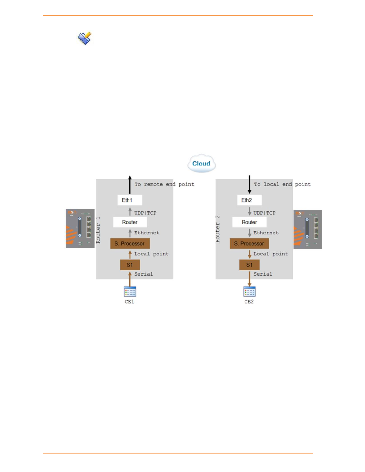
82
NOTE
The aware mode supports IEC 101 addressing only.
The service ‘local-end-point’ must be set with [‘application’= ‘iec101-gw’] and
[‘protocol’=’ iec101’]
19.5 Reference drawing
For ease of explanation of following terms and serial properties at this chapter, the diagram
below will be used as a reference to follow on the serial traffic flow.
The diagram demonstrates two iSG4F routers connected over an Ethernet network and
sharing a transparent serial tunneling service.
iSG4F User’s Manual
iS5 Communications Inc.

iSG4F User’s Manual
83
The customer equipment #1 (CE1) is a serial master sending data to a serial slave CE2. For
simplicity purposes, the diagram and explanations refer to unidirectional traffic from CE1 to
CE2.
19.6 Serial Traffic Direction
Transmit direction represents the serial-processor traffic towards the CE, over the serial port.
Receive direction represents the traffic received at the serial-processor from the CE, over the
serial port.
19.6.1 Serial ports counters
The Tx and Rx counters of the serial ports are controlled by the serial-processor.
Rx counters
• Switch1 – counters will increase when CE1 transmits. Data is received at the
serial-processor via S1 and updates the counters.
• Switch2 – counters are not updated.
Tx counters
• Switch1 – counters are not updated.
• Switch2 –CE1 Data is received over the Ethernet network to router 2 and to the
serial-processor. The serial processor transmits the data to CE2 over S1 and increases the Tx
counters.
iS5 Communications Inc.

84
19.7 Allowed Latency
Allowed latency is the maximum time allowed for the serial-processor to collect serial data
from CE1 transmission, before closing an Ethernet packet and sending it over the cloud.
This parameter refers to round-trip in milliseconds units. It reflects only the time for the serial
processor to collect data, it does not consider the network self-latency.
Allowed latency is applicable in byte mode only.
• Switch1 – as CE1 transmits data to serial processor over S1, the allowed-latency
properties are applicable. For a configured value x at allowed-latency, the serial
processor will collect serial data for up to x/2 milliseconds time and then close the
collected data as an Ethernet packet.
• Switch2- as CE2 is only receiving, the allowed-latency is not of influence
19.8 Tx Delay
Tx-delay is set in bits. It determines a delay to take place by the serial processor before
transmitting serial data to the port.
iSG4F User’s Manual
Depending on the baud rate chosen, and the number of bits, a time is calculated for Tx-delay.
Switch1 – as the serial processor only receives serial data, the tx-delay is of no affect.
Switch2- the Ethernet encapsulated data is received at router 2 and to its
serial-processor. It is then transmitted to CE2 via S1 following a time elapse of the
tx-delay.
The serial-processor will delay transmitting the first serial byte to CE2. Following data
bytes are sent without delay.
19.9 Bus Idle Time
This parameter determines a silence on the serial line to identify frame end.
The configurable value for it is given in number of bits. Depending on the baud rate chosen,
and the number of bits, a time is calculated for bus-idle-time.
19.9.1 Byte mode
When using byte mode, end of byte is determined by stop bits. Bus-idle-time is not applicable
at this mode.
19.9.2 Frame mode
Switch1- the serial-processor will collect serial data transmitted from CE1 until a
silence is identified on the line for a time period equal or above the bus-idle-time.
Switch2- the serial-processor transmits the serial frames to CE2 while maintaining a
gap between frames. The gap is the bus-idle-time.
iS5 Communications Inc.

85
19.10 Example Serial Tunneling
The network below demonstrates a P2P topology of transparent serial tunneling.
Configuration router A (MASTER)
iSG4F User’s Manual
1. configure the gateway (values are example only)
router interface create address-prefix 172.18.212.231/24 vlan 100 purpose
application-host physical-interface eth2
serial port create slot 1 port 1 baudrate 9600 parity even mode-of-operation
transparent
serial local-end-point create slot 1 port 1 service-id 1 application
serial-tunnel position slave
serial remote-end-point create remote-address 172.18.212.230 service-id 1
position master
commit
exit
commit
Configuration router B (SLAVE)
2. Configure the gateway (values are example only)
iS5 Communications Inc.

iSG4F User’s Manual
86
router interface create address-prefix 172.18.212.230/24 vlan 100 purpose
application-host physical-interface eth2
serial port create slot 1 port 1 baudrate 9600 parity even mode-of-operation
transparent
serial local-end-point create slot 1 port 1 service-id 1 application
serial-tunnel position master
serial remote-end-point create remote-address 172.18.212.231 service-id
1 position slave
commit
exit
commit
Protocol Gateway IEC 101 to IEC 104
The iSG4F router, using its application module implements the gateway for IEC101 serial
devices to the IEC104 IP protocol. The IEC101 and IEC104 protocols are fully integrated in the
application module thus allowing the IEC101 slave devices to be represented as a IEC104
server in the IP network and to be addressed as such by IEC104 clients located anywhere in
iS5 Communications Inc.

iSG4F User’s Manual
87
the network.
The gateway implementation consists of 3 functions:
IEC104 Server – The application module will act as a IEC104 server to any IEC104
clients that connect to it over the Ethernet network. This function includes the full
implementation of the state-machine of the IEC104 server, response to keep-alive
test frames and listening of TCP port 2404 for any client requests.
IEC60870 message router – The application module will act as an application router
translating the requests received by the IEC104 server to commands issued by the
IEC101 master with the proper IEC101 address and sending the responses vice versa.
IEC101 Master – The application module will act as a IEC101 master to the IEC101
server devices connected to the assigned serial interfaces in the router. This function
includes the full implementation of the state-machine of the IEC101 master,
initialization and arbitration of the IEC101 bus and issuing commands to the
appropriate IEC101 slave to provide the response to the requests which arrive from
the message router.
The IEC101 devices will be configured with their serial link properties, device address and
ASDU address to be uniquely identified behind the gateway.
Overall the IEC101 devices will be addressed from the IEC104 remote client using the
following hierarchical addressing scheme: IP address of the application module in which the
IEC101/104 gateway is implemented, IEC101 device address, ASDU address and IOA
(Information Object Address - for example, the actual address of the discrete inputs mapped
at the IEC101 RTU).
20.1 Modes of Operation
The gateway supports 2 topologies for the IEC101 devices as defined by the standard:
Balanced Mode – Up to 24 unique IEC-101 servers behind each single gateway
Unbalanced Mode – Up to 32 ASDU addresses behind each IEC101 server device
iS5 Communications Inc.

iSG4F User’s Manual
88
20.2 IEC101/104 Gateway properties IEC 101
System role : Controlling station definition (Master)
Network configuration :
o Point-to-point
o Multiple point-to-point
o Multipoint-party line (planned)
Physical layer
o Transmission speed in monitor & control direction: 300 – 38400bps
Link layer
o Link transmission procedure
Balanced transmission
Unbalanced transmission
o Address field of the link
Not present (balanced transmission only)
One octet
Two octets
Structured values translation
Unstructured
Application layer
o Common address of ASDU
One octet
Two octets
o Information object address
Two octets
iS5 Communications Inc.

89
Three octets
Structured
Unstructured
o Cause of transmission
One octet
Two octets (with originator address)
20.3 IEC101/104 Gateway Configuration
The IEC101/104 gateway can be configured through the systems CLI or as part of an IEC104
network-wide service-group in the iNMS (industrial network management system) tool.
In any case the configuration should include the following parameters:
Application IP address – The application module must be configured with an IP
address and should be associated with a VLAN for the uplink traffic. This application
IP interface acts as the IEC104 server in the Ethernet network and represents all the
IEC101 devices connected locally to the router towards the IEC104 clients.
iSG4F User’s Manual
Optional remote IP addresses - When configuring the IEC104 service-group you
should also provide the IP addresses of the IEC104 clients so the proper
service-aware firewall rules can be defined.
IEC101 device parameters - For the serial interfaces the physical link properties
should be configured (baud-rate ,parity , stop bits). Furthermore the IEC101
addressing information should be provided and the devices should be assigned to the
IEC104/101 gateway.
iS5 Communications Inc.

iSG4F User’s Manual
90
20.4 Gateway 101/104 Configuration Flow
When attending a setup configuration, follow these below steps.
1. Ethernet connectivity towards the IEC 104 Client (SCADA)
a. Set service VLAN and assign relevant ports.
b. Set ACE IP interface with the service VLAN
c. Set static or dynamic routing if needed to reach the IEC 104 Client.
d. Verify by following methods
i. Successful ping between the IEC 104 Client (SCADA) and the iSG4F
designated IP interface.
ii. IEC 104 connection established. Use the command “iec101-gw show all”
to verify connection at the switch.
2. Serial connection towards the locally connected IEC101 server (RTU)
a. Configure a serial port
i. Serial properties as baud rate, parity and such, must be consistent with
those of the RTU.
ii. The serial port must be configured with ‘mode-of-operation set to
‘transparent’.
b. Configure a local service (serial local-end-point)
iS5 Communications Inc.

iSG4F User’s Manual
91
i. Create a local-end-point and assign the serial port.
ii. The local-end-point field ‘application’ must be set to ‘iec101-gw’
c. Enable the gateway
i. Assign the gateway to use the predefined ACE interface.
ii. Set the desired mode ‘balanced’ or ‘unbalanced’.
d. Configure the gateway with the RTU IEC101 properties. Key values are advised
here
i. Common Address of ASDU value (CLI field ‘asdu_addr’). As set at the
RTU.
ii. Common Address of ASDU length in bytes (CLI field
‘common_address_field_length’). As set at the RTU.
iii. Link Address (CLI field ‘link_addr’). As set at the RTU.
iv. Link Address length in bytes (CLI field ‘link_address_field_length’). As set
at the RTU.
v. Cause of Transmission length in bytes, determined by the usage of the
vi. Connect the IEC101 server (RTU) to the serial port with a proper serial
e. Verify by following methods
i. Use the command “iec101-gw show all” to verify the operational status
ii. Follow serial port and gateway counters to check if serial traffic is
3. Trouble shooting
a. Most trouble shooting is usually at the IEC101 connection to the locally
connected RTU. The IEC 104 connection between the gateway and the client
(SCADA) is based on straightforward Ethernet connectivity which is easy to
establish and diagnose.
originator address field in the protocol. (CLI field ‘orig_addr_participate’)
cable. Pin-out of the RS232 RJ45 port of the switch is given in this
manual. Control lines are not supported for the gateway application.
Usage of Tx,Rx and GND lines are allowed.
(‘OP ST’) is UP.
received and transmitted at the serial port.
Show commands “serial port show slot 1 port <x>” and
“iec101-gw cnt show” are available.
b. If the IEC101 (‘OP ST’) is in any other state other than ‘UP’, try the following
i. Verify your serial physical connection.
ii. Verify the RTU is on and properly configured.
iii. Follow the serial port counters to verify traffic is received and
transmitted at the serial port. If only Rx counters are progressing, check
again the serial properties of both the gateway and the RTU (baud rate,
parity and such).
iS5 Communications Inc.

92
iv. Verify the IEC properties are consistent between the gateway and the
RTU (CA, LA, CA length, LA length, COT)
20.5 Gateway 101/104 Commands Hierarchy
+ root
+ serial
+ port
- clear counters
- create {slot <1>} {port <1-2>} {mode-of-operation < transparent
>} [baudrate <9600,(50-368400)>] [parity {no,no| odd| even}]
[stopbits <1|2>] databits {8,<5-8>}
admin-status [up| down]
- update {slot <1>} {port <1-2>} {mode-of-operation < transparent
iSG4F User’s Manual
>} [baudrate <9600,(50-368400)>] [parity {no,no| odd| even}]
[stopbits <1|2>] databits {8,<5-8>}
admin-status [up| down]
- show
+ local-end-point
- create create {slot <1>} {port <1-2>} {application
<iec101-gw>}{service-id <1-100>} [position <slave>]
- remove {slot <1>} {port <1-2>} {service-id <1-100>}
- show
+ iec101-gw
- operation {start | stop}
- cnt show
- show {all| iec101 {log| state} {slot <1>} {port <1-2>} }
+ config
- gw update mode {balanced,(balanced| unbalanced)} ip_addr <A.B.C.D>
- iec101 {create | update}
{slot <1>} {port <1-2>} {asdu_addr {(1-255)| (1-65534)}}
{link_addr {(1-255)| (1-65534)}}
[common_address_field_length <2,(1|2)>]
[translated_cmn_addr {(1-255)| (1-65534)}]
[link_address_field_length <2,(1|2)>]
[ioa_length <3,(1|2|3)>] [orig_address <1-255>]
[orig_addr_participate <y,(y|n)>]
iS5 Communications Inc.

iSG4F User’s Manual
93
Command
Description
iec101-gw
Configuration mode of 101/104 gateway
Operation
Start : activate the gateway
Stop : stop the gateway
*takes effect on all IEC 101 nodes connected to
the switch
Config
gw update mode
Unbalanced – for 101 servers unbalanced
topology.
Balanced (default)– for 101 servers balanced
topology.
ip_addr– IP address of a chosen application IP
interface. The IP interface must be configured
prior to it be used by the gateway
!changing this field requires reloading the unit
iec101 create
| update |
Slot ,Port: physical interface where the 101
slave is connected at.
[dir_bit<AUTO,(AUTO|0|1)>] [single_char <y,(n|y)>]
[test_proc <y,(n|y)>] [gen_inter <n,(n|y)>] [time_tag
<n,(n|y)>]
- iec101 remove [slot <1>] {port <1-2>}
- iec101 [add_asdu | remove_asdu] port <1-2>
{asdu_addr {(1-255)| (1-65534)}} {link address {(1-255)|
(1-65534)}}
- iec101 [add_ioa_trans>| remove_ioa_trans] port <1-2>
src_ioa {a1-a2-a3| a1-a2| a} trans_ioa {a1-a2-a3| a1-a2| a}
- iec104 {update | remove} {ip_addr <>} [clock_sync <n|y>] [orig_addr
<>] [t0 <30sec,[1-255]>] [t1 <15sec,[1-255]>] [t2
<10sec,[1-255]>] [t3 <20sec,[1-255]>]
20.6 Gateway 101/104 Commands
iS5 Communications Inc.

iSG4F User’s Manual
94
Command
Description
remove
asdu_addr : Common Address of ASDU. Usually
Should be configured as the ASDU address of the
IEC101 Server unless a translation service is
required. In the latter case, should be
configured as the address which is set at the
104 Client for the server. A decimal value of
1-255 or 1-65534 is allowed depending if
‘common_address_field_length’ is set to one
byte or two.
common_address_field_length: length in bytes of
the Common Address of ASDU. Permissible values
are one or two bytes. Should be identical to
the configuration at the IEC 101 server.
translated_cmn_addr – used when a translation
service required for the common address of
asdu. The value should be identical to the
actual common address of the IEC101 Server.
A decimal value of 1-255 or 1-65534 is allowed
depending if ‘common_address_field_length’ is
set to one byte or two.
link_addr: Should be configured as the Link
address of the 101 slave. A decimal value of
1-255 or 1-65534 is allowed depending if
‘link_address_field_length’ I set to one byte
or two.
link_address_field_length: length in bytes of
the Link Address. Permissible values are one
or two bytes. Should be identical to the
configuration at the 101 slave.
iS5 Communications Inc.

iSG4F User’s Manual
95
Command
Description
orig_addr: Should be configured as the
Originator address set at the 101 slave.
orig_addr_participate: y|n to indicate if the
101 slave uses the originator address field.
Should be identical to the configuration at the
101 slave.
The Cause Of Transmission (COT) will be
influenced by this configuration.
'y' – COT will be 2 byte in size.
'n' - COT will be 1 byte in size.
dir_bit: y|n are Permissible values. Should be
oposite to the configuration at the 101 slave.
relevant in Balanced mode only.
single_char: y|n are Permissible values.Should
be configured identical to the 101 slave
configuration.
Relevant in Balanced mode only.
ioa_len – IO object length. Permissible values
are 1|2|3 bytes. Should be identical to the
configuration at the 101 slave.
[add_ioa_tran
s>|
remove_ioa_tr
ans]
Slot, Port: physical interface where the 101
slave is connected at.
src_ioa: value of the 101 server Object address
as set at the 104 client. May be 1/2/3 bytes long
depending on the settings of ‘ioa_length’. A
value is expected as ‘byte1’-‘byte2’-‘byte3’ or
‘byte1’-‘byte2’ or
‘byte-1’.
Permissible value for each byte is 1-255.
example for 3 bytes size IOA: 5-212-151.
iS5 Communications Inc.
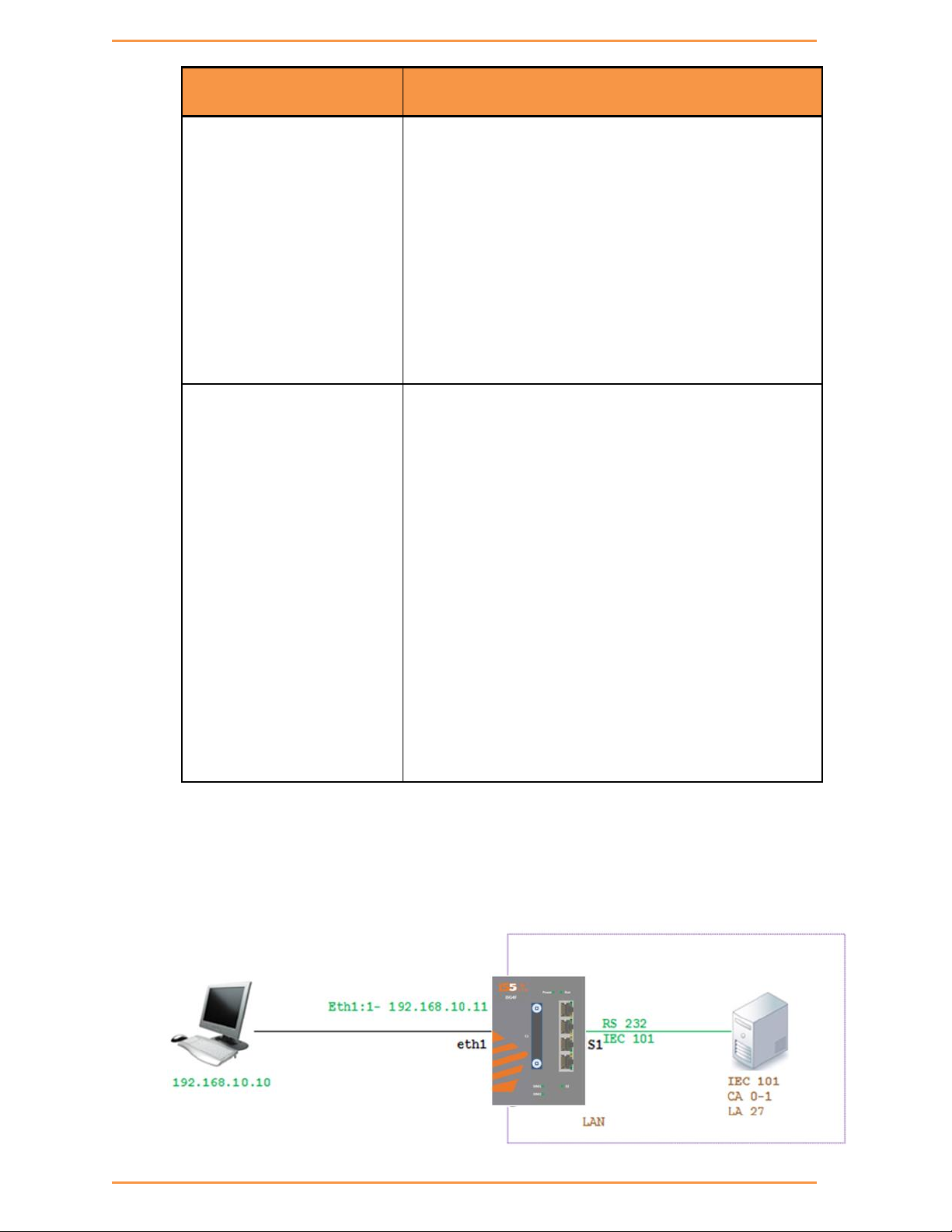
iSG4F User’s Manual
96
Command
Description
trans_ioa: value of the 101 server Object
address. May be 1/2/3 bytes long depending on the
settings of ‘ioa_length’. A value is expected as
‘byte1’-‘byte2’-‘byte3’ or
‘byte1’-‘byte2’ or
‘byte-1’.
Permissible value for each byte is 1-255.
example for 3 bytes size IOA: 5-212-151.
iec104
{update |
remove}
ip_addr: IP address of the SCADA
orig_addr: originator address of the SCADA.
to: Time-out of connection establishment
t1: Time-out of send or test APDUs
t2 : Time-out for acknowledges in case of no data
messages t2 < t1
t3: Time-out for sending test frames in case of
a long idle state
20.7 Example Gateway 101/104
The network below demonstrates an IEC 101/104 setup using the iSG4F as a gateway.
iS5 Communications Inc.

iSG4F User’s Manual
97
Configuration
1. Configure an IP interface for the gateway.
iSG4F#router interface create address-prefix 192.168.10.11/24
physical-interface eth1 description Network purpose application-host
2. Configure the serial port properties. Field ‘mode-of-operation must be set to ‘transparent’. The port
properties must be in-line with the IEC 101 server device connected (same baud rate, parity, stop bits,
data bits and such).
serial port create port 1 mode-of-operation transparent baudrate 9600 parity
even
3. Create the local serial service for the port. the field ‘application’ must be set to ‘iec101-gw’
serial local-end-point create port 1 service-id 1 application iec101-gw
4. Configure the gateway mode of operation and choose the ACE interface to be used. The IP interface
must be available in advance.
iec101-gw config gw update mode balanced ip_addr 192.168.10.11
5. Configure the gateway properties to be in line with the IEC101 server settings.
iec101-gw config iec101 create port 1 asdu_addr 1 orig_addr 0 link_addr 27
link_address_field_length 2 common_address_field_length 2
orig_addr_participate y
commit
6. Follow show status
iS5 Communications Inc.

iSG4F User’s Manual
98
Terminal Server
21.1 Terminal Server service
iS5 routers allows a special service for transposing of a TCP session to serial session.
Networking:
A router acting as the terminal server can be connected to the Ethernet telnet client
(management station) via:
local connection at its ports or
Via IP network.
In both cases the connection is TCP based.
A router acting as the terminal server can be connected to the serial end device (managed
station) via:
local connection at its RS-232 ports or
Over UDP connection to a remote iS5 router to which the serial device is connected
directly to.
In this case there will be a “transparent serial tunneling service” over the IP network
(encapsulation of serial data in UDP|TCP packets)
iS5 Communications Inc.

iSG4F User’s Manual
99
A example, console ports of remote devices to be reached via terminal server service using
telnet from any PC with Ethernet link.
In the drawing below the management station (PC) is a Telnet client which requires being able
to manage the remote RTUs with a text based shell method.
The PC is an Ethernet device connected locally to the router A.
Router A acts as a telnet server towards it. A telnet session is hence established between the
PC and the router.
Up to 100 such sessions can simultaneously be supported, uniquely identified by their TCP
Port numbers.
It is possible to support P2MP in 2 modes:
Over the same service using the same TCP port number.
Over different services using multiple TCP sessions each with a different TCP port.
The user will configure services ,to determine which RTU is to be addressed via which telnet
session.
In bellow example Serial transparent tunneling (UDP|TCP traffic) will take place between the
iS5 routers thus establishing the paths from the serial RTUs to router A . Using the mapping
between the telnet sessions and the serial services the application will direct the traffic from
the management station to the RTUs allowing each its own path for management.
Below is a second option at which the terminal servers are set at the remote router where
the serial devices are connected locally.
The benefit in this scenario is having a TCP session over the IP network.
iS5 Communications Inc.

iSG4F User’s Manual
100
21.2 Terminal Server Commands Hierarchy
+ root
+ serial
+ port
- clear counters
- create slot <1> port <1-2> [baudrate <9600,(50-368400)>]
databits {8,<5-8>} [parity {no,no| odd| even}] [stopbits
<1,1|2>]
[bus-idle-time <bits (30-1000>]
[mode-of-operation <transparent>]
admin-status [up| down]
- remove slot <1> port <1-2>
- show [slot <1> port <1-2>]
+ local-end-point
- create slot <1> port <1-2> service-id <1-100> position <slave>
application <terminal-server>
- remove slot <1> port <1-2> service-id <1-100>
- show
+ terminal-server
- admin-status [enable | disable | show]
- services show [service-id <>]
iS5 Communications Inc.
 Loading...