


iSG18GFP User Manual R3.5
Ver: 1.3
Date: 04.28.2015
iS5 Communications Inc.
#3-7490 Pacific Circle, Mississauga, Ontario, L5T 2A3
Tel: + 905 670 0004
Fax: + 289 401
Website: www.iS5Com.com
E-mail: support@iS5Com.com
Intelligent Flexible Secure Gateway
IEC 61850-3 and IEEE 1613 compliant
iSG18GFP User Manual
Version 1.2
March 2015

iSG18GFP User Manual R3.5
Ver: 1.3
Date: 04.28.2015
Tel: + 905-670-0004
Fax: + 289-401-5206
Technical Support E-mail: support@iS5Com.com
Sales Contact E-mail: sales@iS5Com.com
Copyright Notice
Copyright © 2013 iS5 Communications Inc. All rights reserved.
No part of this publication may be reproduced in any form without the prior written consent of iS5 Communications Inc.
(iS5).
Trademarks
iS5Com is a registered trademark of iS5. All other trademarks belong to their respective owners.
Regulatory Compliance Statement
Product(s) associated with this publication complies/comply with all applicable regulations. Please refer to the Technical
Specifications section for more details.
Warranty
iS5 warrants that all products are free from defects in material and workmanship for a specified warranty period from the
invoice date (5 years for most products). iS5 will repair or replace products found to be defective within this warranty
period including shipping costs. This warranty does not cover product modifications or repairs done by persons other
than iS5-approved personnel, and this warranty does not apply to products that are misused, abused, improperly
installed, or damaged by accident.
Please refer to the Technical Specifications section for the actual warranty period(s) of the product(s) associated with this
publication.
Disclaimer
Information in this publication is intended to be accurate. iS5 shall not be responsible for its use or infringements on
third-parties as a result of its use. There may occasionally be unintentional errors on this publication. iS5 reserves the
right to revise the contents of this publication without notice.
Contact Information
iS5 Communications Inc.
#3-7490 Pacific Circle, Mississauga, Ontario, L5T 2A3
Website: www.iS5Com.com
iS5 Communications Inc. Page: 2 of: 465

iSG18GFP User Manual R3.5
Ver: 1.3
Date: 04.28.2015
Date
Rev’
Description
Prepared by
Approved by
10/08/2014
1.0
Initial release of 3.5
Alice Zhang
Boris Tseitin
03/09/2014
1.1
Updates
Boris Tseitin
Boris Tseitin
03/27/2015
1.2
Update
Boris Tseitin
Boris Tseitin
04/28/2015
1.3
Serial Pin Out Update
Boris Tseitin
Boris Tseitin
Revision History/Approvals:
This user guide includes the relevant information for utilizing the IS5 Communications iSG18GFP switches.
The information in this document is subject to change without notice and describes only the product defined in the
introduction of this document.
This document is intended for the use of customers of IS5 Communications only for the purposes of the agreement under
which the document is submitted, and no part of it may be reproduced or transmitted in any form or means without the
prior written permission of IS5 Communications.
The document is intended for use by professional and properly trained personnel, and the customer assumes full
responsibility when using it.
If the Release Notes that are shipped with the device contain information that conflicts with the information in this
document or supplements it, the customer should follow the Release Notes.
The information or statements given in this document concerning the suitability, capacity, or performance of the relevant
hardware or software products are for general informational purposes only and are not considered binding. Only those
statements and/or representations defined in the agreement executed between IS5 Communications and the customer
shall bind and obligate IS5 Communications.
IS5 Communications however has made all reasonable efforts to ensure that the instructions contained in this document
are adequate and free of material errors. IS5 Communications will, if necessary, explain issues which may not be covered
by the document.
IS5 Communications sole and exclusive liability for any errors in the document is limited to the documentary correction of
errors. IS5 COMMUNICATIONS IS NOT AND SHALL NOT BE RESPONSIBLE IN ANY EVENT FOR ERRORS IN THIS DOCUMENT
OR FOR ANY DAMAGES OR LOSS OF WHATSOEVER KIND, WHETHER DIRECT, INCIDENTAL, OR CONSEQUENTIAL
(INCLUDING MONETARY LOSSES), that might arise from the use of this document or the information in it.
This document and the product it describes are the property of IS5 Communications, which is the owner of all intellectual
property, rights therein, and are protected by copyright according to the applicable laws.
Other product and company names mentioned in this document reserve their copyrights, trademarks, and registrations;
they are mentioned for identification purposes only
Copyright © 2013 iS5 Communications Inc. All rights reserved.
iS5 Communications Inc. Page: 3 of: 465

iSG18GFP User Manual R3.5
Ver: 1.3
Date: 04.28.2015
Contents
Copyright Notice ························································································································· 2
Trademarks ································································································································· 2
Regulatory Compliance Statement ···························································································· 2
Warranty ···································································································································· 2
Disclaimer ··································································································································· 2
Contact Information ··················································································································· 2
Revision History/Approvals: ······································································································· 3
Contents ·································································································································· 4
Introduction ·························································································································· 17
Key Features ····························································································································· 17
Using This Document ············································································································· 18
Documentation Purpose ·········································································································· 18
Intended Audience ··················································································································· 18
Documentation Suite················································································································ 18
Conventions Used ····················································································································· 19
Hardware and Interfaces ········································································································ 20
Introduction ······························································································································ 20
Ordering options of Hardware ································································································· 20
Graphical view of Hardware ····································································································· 21
Front Panel ························································································································ 21
Rear ··································································································································· 22
Bottom ······························································································································ 22
Configuration Environment ···································································································· 23
iS5 Communications Inc. Page: 4 of: 465
Side view ··························································································································· 22
Logical System View ················································································································· 23
Command Line Interface ·········································································································· 23
Supported Functionalities ········································································································ 25
System Default state ················································································································ 29
Root Commands ······················································································································· 29
Root Commands Description ···································································································· 31

iSG18GFP User Manual R3.5
Ver: 1.3
Date: 04.28.2015
GCE Commands ························································································································ 32
GCE Commands Description ····································································································· 34
ACE Commands ························································································································ 40
Main Show Commands ············································································································· 41
GCE ···································································································································· 41
ACE ···································································································································· 42
System Version and Data Base ······························································································· 44
Configuration Database ············································································································ 44
OS VERSION ······························································································································ 44
Running Configuration ············································································································· 45
Commands Hierarchy ··············································································································· 45
Example upgrade the OS from USB ·························································································· 46
Example upgrade the OS from SFTP ························································································· 47
Example export db and logs ····································································································· 48
Example handling db files on flash ··························································································· 48
Example Import db from TFTP ·································································································· 48
Safe Mode ································································································································ 49
SW Image upgrade and Recovery ····················································································· 50
Install OS image update from a USB ················································································· 51
Installing First OS image from a USB ················································································ 54
System Database Import/ Export ····················································································· 55
Port Interfaces ······················································································································· 57
Port addressing ························································································································· 57
Graphical view of system Interfaces ························································································ 57
A logical view of ports ·············································································································· 58
Enabling Ports ··························································································································· 59
ACE Ports ·································································································································· 59
iS5 Communications Inc. Page: 5 of: 465
Default state ····················································································································· 59
Vlan assignment ················································································································ 60
Ports FE 0/9-0/16 ····················································································································· 60
POE Ports ·································································································································· 61
Power Management of POE ····························································································· 61
Modes of POE ··················································································································· 62

iSG18GFP User Manual R3.5
Ver: 1.3
Date: 04.28.2015
POE command Hierarchy ·································································································· 63
POE Commands Description ····························································································· 63
Controlling Ports ······················································································································· 64
Storm Control ··················································································································· 64
Rate Limit Output ············································································································· 64
Ports command Hierarchy ········································································································ 64
Port Commands Description ···································································································· 65
Port Configuration Example ······························································································ 68
Configuration Output Example ························································································· 68
Login and Management·········································································································· 69
Login Authentication Hierarchy ································································································ 69
Login Authentication Commands Description·········································································· 71
Examples ··································································································································· 73
Privilege level···························································································································· 74
Commands Description ···································································································· 74
Serial Console Port ··················································································································· 75
Connecting to the Console Port ························································································ 75
CLI Console Commands ···································································································· 76
Management ···························································································································· 76
Default state ····················································································································· 77
Commands Hierarchy ······································································································· 77
Commands Description ···································································································· 78
Example ···························································································································· 79
System Alias ······························································································································ 81
iS5 Communications Inc. Page: 6 of: 465
CLI Pagination ··························································································································· 81
MAC-Address Table (FDB) ········································································································ 82
Port Mac Learning and limit ····························································································· 82
Commands Hierarchy ······································································································· 82
Configuration Example ····································································································· 83
IP ARP Table ······························································································································ 83
Commands Hierarchy ······································································································· 83
Commands Description ···································································································· 84
Configuration Example ····································································································· 84

iSG18GFP User Manual R3.5
Ver: 1.3
Date: 04.28.2015
VLAN ····································································································································· 86
VLANs of System Usage ············································································································ 86
VLAN Range of NMS Usage ······································································································ 86
VLAN Configuration Guidelines ································································································ 86
VLAN Default state············································································································ 87
Vlan ports ·························································································································· 87
Enabling VLAN ··················································································································· 88
Vlan command Hirarchy ··································································································· 88
Configuration Example ····································································································· 89
IP Interfaces ··························································································································· 91
GCE IP Interfaces ······················································································································ 91
Commands Hierarchy ······································································································· 91
Commands Description ···································································································· 92
Default state ····················································································································· 93
Configuration Examples ···································································································· 93
Static & Dynamic switch Default IP Address assignment ··········································· 93
ACE IP Interfaces ······················································································································ 96
ACE IP Interface Commands Hierarchy ············································································· 96
ACE IP Interface Commands Description ·········································································· 97
Example for creating ACE IP Interface ·············································································· 97
Diagnostic ······························································································································ 98
System Environment ················································································································ 98
Environment Command Hierarchy ··················································································· 98
Environment Commands Description ··············································································· 99
RMON ····································································································································· 100
Commands Hierarchy ····································································································· 100
iS5 Communications Inc. Page: 7 of: 465
Commands Description ·································································································· 100
Example ·························································································································· 101
System logs export ················································································································· 101
Commands Hierarchy ····································································································· 101
Commands Description ·································································································· 102
Capture Ethernet service traffic ····························································································· 102

iSG18GFP User Manual R3.5
Ver: 1.3
Date: 04.28.2015
Commands Hierarchy ····································································································· 102
Commands Description ·································································································· 103
Example ·························································································································· 103
DDM ········································································································································ 105
Commands Hierarchy ····································································································· 105
Commands Description ·································································································· 105
Example ·························································································································· 106
Debugging ······························································································································· 108
Commands Hierarchy ····································································································· 108
Commands Description ·································································································· 109
Syslog ······································································································································ 110
The Priority indicator ······································································································ 110
GCE Message Format ······································································································ 111
ACE Message Format ······································································································ 112
Commands Hierarchy ····································································································· 121
Commands Description ·································································································· 122
Configuration Example ··································································································· 124
Output example ·············································································································· 125
Alarm Relay ···························································································································· 126
ALARM Interface ············································································································· 126
Supported Alarms ··········································································································· 127
Default state ··················································································································· 127
Commands Hierarchy ····································································································· 128
Commands Description ·································································································· 128
Monitor Session ······················································································································ 130
Commands Hierarchy ····································································································· 130
SNMP ·································································································································· 131
iS5 Communications Inc. Page: 8 of: 465
Commands Description ·································································································· 131
Example ·························································································································· 131
Supported traps ······················································································································ 131
SNMP command Hierarchy ···································································································· 131
SNMP command Description ································································································· 133

iSG18GFP User Manual R3.5
Ver: 1.3
Date: 04.28.2015
Example ·································································································································· 139
Clock and Time ···················································································································· 139
Local Clock ······························································································································ 139
Commands Hierarchy ····································································································· 139
Commands Description ·································································································· 140
SSH ······································································································································ 148
DHCP ··································································································································· 150
DHCP Server ························································································································ 151
Example ·························································································································· 140
SNTP ······································································································································· 140
SNTP command Hierarchy······························································································· 140
SNTP Commands Descriptions ·························································································· 142
Example ·························································································································· 147
SSH Command Hierarchy ········································································································ 148
SSH Commands Descriptions ·································································································· 148
DHCP Client and Snooping Commands Hierarchy ·································································· 150
DHCP Server Commands Hierarchy ························································································ 151
DHCP Relay Commands Description ······················································································ 152
Example ·························································································································· 153
DHCP Relay ·························································································································· 157
DHCP Relay Command Hierarchy ··························································································· 157
DHCP Relay Commands Description ······················································································ 157
Example ·································································································································· 161
RADIUS ································································································································ 163
TACACS ································································································································ 166
iS5 Communications Inc. Page: 9 of: 465
RADIUS Command Hierarchy ································································································· 163
RADIUS Commands Descriptions ··························································································· 163
Example ·································································································································· 165
Default Configurations ··········································································································· 166
TACACS Command Hierarchy ································································································· 166
TACACS Commands Descriptions ··························································································· 167
Configuration Example ··········································································································· 168

iSG18GFP User Manual R3.5
Ver: 1.3
Date: 04.28.2015
802.1x ································································································································· 169
802.1x Commands Hierarchy ································································································· 169
802.1x Commands Descriptions ····························································································· 170
Examples ································································································································· 175
IGMP Snooping ···················································································································· 176
IGS Commands Hierarchy ······································································································· 176
IGS Commands Descriptions ·································································································· 176
Example ·································································································································· 179
ACLs ···································································································································· 181
ACL Flow validation at a Port·································································································· 181
ACL Commands Hierarchy ······································································································ 183
ACL Commands Descriptions ·································································································· 184
Configuration Example ··········································································································· 190
Flow Example·························································································································· 192
Test 1 ······························································································································ 192
Test 2 ······························································································································ 193
Test 3 ······························································································································ 194
Test 4 ······························································································································ 195
QOS ····································································································································· 197
Test 5 ······························································································································ 196
QOS Commands Hierarchy ····································································································· 197
QOS Commands Descriptions ································································································· 199
Port based assignment of priority ·························································································· 207
Link Aggregation ·················································································································· 211
STP ······································································································································ 219
iS5 Communications Inc. Page: 10 of: 465
Setting a Scheduling Algorithms ····························································································· 207
Traffic Filtering at Ingress ······································································································· 208
Setting a Shaper per Egress Port ···························································································· 208
Map 802.1p to COS················································································································· 208
Set VPT or DSCP ······················································································································ 209
LAG command Hierarchy ········································································································ 214
LAG Commands Descriptions ································································································· 215
Example ·································································································································· 217

iSG18GFP User Manual R3.5
Ver: 1.3
Date: 04.28.2015
STP Description ······················································································································· 220
Bridge ID and Switch Priority ·································································································· 221
Election of the Root Switch ···································································································· 221
Default state ··················································································································· 221
STP Hierarchy ························································································································· 222
Commands Descriptions ········································································································· 222
RSTP/MSTP ·························································································································· 228
RSTP Description ···················································································································· 228
Port States ······························································································································ 228
Port Roles ······························································································································· 228
Rapid Convergence ················································································································· 229
Proposal Agreement Sequence ······························································································ 229
Topology Change and Topology Change Detection ······························································· 230
Default Configurations ···································································································· 230
Setting Spanning Tree Compatibility to STP ··········································································· 231
Configuring Spanning Tree Path Cost ····················································································· 233
Configuring Spanning Tree Port Priority ················································································· 236
Configuring Spanning Tree Link type ······················································································ 238
Configuring Spanning Tree Portfast ················································································ 240
Configuring Spanning Tree Timers ·················································································· 241
Enhanced RSTP ···················································································································· 241
Method of operation ·············································································································· 241
Enhanced RSTP Command Hierarchy ····················································································· 244
Commands Descriptions ········································································································· 244
LLDP ···································································································································· 245
LLDP Commands Hierarchy ···································································································· 245
LLDP Commands Descriptions ································································································ 246
Example 1 ······························································································································· 257
OSPF ···································································································································· 262
iS5 Communications Inc. Page: 11 of: 465
Show LLDP······················································································································· 258
Example 2 ······························································································································· 260
Show LLDP······················································································································· 261
OSPF GCE Commands Hierarchy ···························································································· 262

iSG18GFP User Manual R3.5
Ver: 1.3
Date: 04.28.2015
OSPF GCE Commands Descriptions ························································································ 264
OSPF ACE Commands Hierarchy····························································································· 280
OSPF ACE Commands Descriptions ························································································ 281
OSPF setup example ··············································································································· 282
VRRP ··································································································································· 286
RIP Commands Hierarchy ······································································································· 286
VRRP Commands Descriptions ······························································································· 287
Example ·································································································································· 287
RIPv2 ··································································································································· 290
GCE RIP Commands Hierarchy ······························································································· 290
GCE RIP Commands Descriptions ··························································································· 290
ACE RIP Commands Hierarchy ································································································ 292
ACE RIP Commands Descriptions ··························································································· 293
Example ·································································································································· 294
OAM CFM ···························································································································· 297
CFM Command Hierarchy ······································································································ 298
CFM Commands Descriptions ································································································ 299
ERPS ···································································································································· 306
ERPS Commands Hierarchy ···································································································· 306
ERPS Commands Descriptions ································································································ 308
ERP setup example ················································································································· 323
Serial Ports and Services ······································································································ 335
Serial interfaces ······················································································································ 336
iS5 Communications Inc. Page: 12 of: 465
Services configuration structure ···························································································· 336
Serial Commands Hierarchy ··································································································· 337
Serial Commands Description ································································································ 338
Declaration of ports ················································································································ 343
Default State ··························································································································· 343
System default VLAN 4093 ····································································································· 343
Serial default VLAN 4092 ········································································································ 343
RS- 232 Port Pin Assignment ·································································································· 345
RS- 232 Serial cable ················································································································ 346
Led States ······························································································································· 346

iSG18GFP User Manual R3.5
Ver: 1.3
Date: 04.28.2015
Transparent Serial Tunneling ································································································ 347
Concept of Operation ············································································································· 347
Supported Network topologies ······························································································ 348
Point to Point ·················································································································· 348
Point to multipoint point ································································································ 349
Multi Point to multipoint point ······················································································ 350
Modes of Operation ··············································································································· 350
Port Mode Of Operation ································································································· 350
Service Buffer Mode ······································································································· 351
Byte ································································································································· 351
Addressing Aware Modes ······································································································· 351
Non aware mode ············································································································ 351
Aware mode ··················································································································· 352
Reference drawing ················································································································· 353
Serial Traffic Direction ············································································································ 354
Serial ports counters ······································································································· 354
Allowed latency ······················································································································ 354
Tx Delay ·································································································································· 354
Bus Idle Time ·························································································································· 355
Byte mode ······················································································································· 355
Frame mode ···················································································································· 355
Bits for Sync ···························································································································· 356
bits-for-sync1 ·················································································································· 356
bits-for-sync2 ·················································································································· 356
Terminal Server ··················································································································· 364
iS5 Communications Inc. Page: 13 of: 465
RS-232 Control lines ··············································································································· 357
Modes of operation ········································································································ 358
Example Serial Tunneling ······································································································· 362
Terminal Server service ·········································································································· 364
Terminal Server Commands Hierarchy··················································································· 365
Terminal Server Commands ··································································································· 366
Example local Service ············································································································· 370
Example Networking ·············································································································· 373

iSG18GFP User Manual R3.5
Ver: 1.3
Date: 04.28.2015
Modbus Gateway ················································································································· 375
Implementation ······················································································································ 375
Modbus Gateway Commands Hierarchy ················································································ 375
Modbus Gateway Commands Description ············································································· 376
Example ·································································································································· 377
DNP3 Gateway ····················································································································· 380
Example ·································································································································· 380
Protocol Gateway IEC 101 to IEC 104 ···················································································· 382
Modes of Operation ··············································································································· 382
IEC101/104 Gateway properties IEC 101 ··············································································· 383
IEC101/104 Gateway Configuration ······················································································· 384
Gateway 101/104 Configuration Flow ··················································································· 385
Gateway 101/104 Commands Hierarchy ··············································································· 386
Gateway 101/104 Commands ································································································ 387
Example Gateway 101/104 ···································································································· 389
VPN ····································································································································· 392
Background ····························································································································· 392
Modes supported ··················································································································· 392
Layer 2 VPN ····················································································································· 392
Layer 3 DM-VPN ·············································································································· 393
L2-VPN Commands Hierarchy ································································································ 393
L2-VPN Commands ················································································································· 393
L3 DM-VPN Commands Hierarchy ·························································································· 394
L3 IPSec-VPN Commands Hierarchy ······················································································· 395
iS5 Communications Inc. Page: 14 of: 465
IPSec ··································································································································· 396
Applications ···························································································································· 396
Authentication Header (AH) ··································································································· 396
Encapsulating Security Payload (ESP) ····················································································· 396
Security Associations ·············································································································· 396
ISAKMP ··································································································································· 396
IKE ··········································································································································· 397
ISAKMP Phase 1 ·············································································································· 397
ISAKMP Phase 2 ·············································································································· 403

iSG18GFP User Manual R3.5
Ver: 1.3
Date: 04.28.2015
IPSec Command Association ·································································································· 404
IPSec Commands Hierarchy ···································································································· 405
IPsec Commands ···················································································································· 406
IPSec defaults ·················································································································· 410
GPRS/UMTS Interface ·········································································································· 411
Overview································································································································· 411
Hardware ································································································································ 411
Method of operation ·············································································································· 412
SIM card state ················································································································· 412
Discrete IO Tunneling ··········································································································· 426
Backup and redundancy ································································································· 414
GPRS/UMTS Commands Hierarchy ························································································ 417
GPRS/UMTS Commands Description ····················································································· 418
Default State ··························································································································· 420
Led States ······························································································································· 420
Example for retrieving the IMEI ····························································································· 421
Example for Sim Status ··········································································································· 421
Example Cellular Watch Dog ·································································································· 423
Discrete channel interfaces ···································································································· 426
Hardware ································································································································ 426
Services ··································································································································· 427
Diagnostics and logic states ··································································································· 427
Technical data ························································································································ 427
Discrete IO tunneling Commands Hierarchy ·········································································· 428
Discrete IO tunneling Commands ··························································································· 428
VPN Setup Examples ············································································································ 429
L2 VPN over Layer 3 cloud ······································································································ 429
iS5 Communications Inc. Page: 15 of: 465
Network drawing ············································································································ 429
Configuration ·················································································································· 429
Implementing IPSec ········································································································ 432
L3 IPSec VPN over Layer 3 cloud ···························································································· 433
Network drawing ············································································································ 433
Configuration ·················································································································· 434

iSG18GFP User Manual R3.5
Ver: 1.3
Date: 04.28.2015
L2 VPN over Cellular Setup ····································································································· 437
Gateway 101/104 over L2 Cellular Setup ·············································································· 443
Terminal Server and Serial tunneling over L2 Cellular Setup ················································· 448
L3 DM-VPN over Cellular Setup ······························································································ 453
Network drawing ············································································································ 454
Configuration ·················································································································· 454
Testing the setup ············································································································ 457
Adding a terminal server service ···················································································· 458
Adding a transparent serial tunneling service ································································ 458
Application Aware Firewall ·································································································· 460
Firewall Service flow ··············································································································· 460
Firewall Flow Illustration ········································································································ 460
Supported Hardware ·············································································································· 461
Configuration ·························································································································· 461
Example ·································································································································· 462
Firewall Commands Hierarchy ······························································································· 464
Firewall Commands ················································································································ 464
iS5 Communications Inc. Page: 16 of: 465

iSG18GFP User Manual R3.5
Ver: 1.3
Date: 04.28.2015
Introduction
The IS5 Communications Service-aware Industrial Ethernet switches combine a ruggedized Ethernet platform with a
unique application-aware processing engine.
As an Industrial Ethernet switches the IS5 Communications switches provide a strong Ethernet and IP feature-set with a
special emphasis on the fit to the miSG18GFPion-critical industrial environment such as fit to the harsh environment, high
reliability and network resiliency.
In addition the IS5 Communications switches have unique service-aware capabilities that enable an integrated handling of
application-level requirements such as implementation of security measures.
Such an integrated solution results in simple network architecture with an optimized fit to the application requirements.
Key Features
The IS5 Communications iSG18GFP devices offer the following features:
Wire speed, non-blocking Layer 2 switching
Dynamic and static layer 3 routing
Compact systems with flexible ordering options of interfaces type /quantity
Advanced Ethernet and IP feature-set
Integrated Defense-in-Depth tool-set
Ethernet and Serial interfaces
Cellular mode
Fit to harsh industrial environment
Supported by a dedicated industrial service management tool (iSIM)
iS5 Communications Inc. Page: 17 of: 465

iSG18GFP User Manual R3.5
Ver: 1.3
Date: 04.28.2015
You are:
Document Function
Function
Installation Guide
Contains information about installing the hardware and
software; including site preparation, testing, and safety
information.
User Guide
Contains information on configuring and using the system.
Release Notes
Contains information about the current release, including new
features, resolved iSG18GFPues (bug fixes), known
iSG18GFPues, and late-breaking information that supersedes
information in other documentation.
Using This Document
Documentation Purpose
This user guide includes the relevant information for configuring the IS5 Communications iSG18GFP functionalities.
It provides the complete syntax for the commands available in the currently-supported software version and describes
the features supplied with the device.
For more information regarding the device installation, refer to the Installation and Maintenance chapter.
For the latest software updates, see the Release Notes for the relevant release. If the release notes contain information
that conflicts with the information in the user guide or supplements it, follow the release notes' instructions.
Intended Audience
This user guide is intended for network administrators responsible for installing and configuring network equipment.
Users must be familiar with the concepts and terminology of Ethernet and local area networking (LAN) to use this User
Guide.
Documentation Suite
This document is just one part of the full documentation suite provided with this product.
iS5 Communications Inc. Page: 18 of: 465

iSG18GFP User Manual R3.5
Ver: 1.3
Date: 04.28.2015
NOTE
Indicating special information to which the user needs to pay special attention.
CAUTION
Indicating special instructions to avoid possible damage to the product.
DANGER
Indicating special instructions to avoid possible injury or death.
Conventions
Description
commands
CLI and SNMP commands
command example
CLI and SNMP examples
<Variable>
user-defined variables
(numerical variable)
numerical variable
{mandatory command parameters}
CLI syntax
[Optional Command Parameters]
CLI syntax
Conventions Used
The conventions below are used to inform important information:
The table below explains the conventions used within the document text:
iS5 Communications Inc. Page: 19 of: 465

iSG18GFP User Manual R3.5
Ver: 1.3
Date: 04.28.2015
Ethernet Port 1-8
Ethernet Port 9-10
Option 1
Description
8RJ45
| | 8 x 10/100 Base TX RJ45
8PRJ45
| | 8 x 10/100 Base TX RJ45 PoE Ports 30W Max per port***
xx | None
2GSFP
|
2 x 100/1000 Base X SFP Port (Blank no SFP transceiver**)
xx
None
8RJ45
8 x 10/100 Base TX RJ45
8SFP
8 x 100 Base X SFP Port (Blank no SFP transceiver)
4SRJ45
4 x RS232 RJ45 Serial Ports with 2KV Isolation
2SIM
Dual SIM GPRS/UMTS Modem
6GCX
4 x RS232 RJ45 Serial Ports with 2KV Isolation + Dual SIM
OSPF
VRRP
RIP
IEC 104 Firewall
DNP3 Firewall
Modbus Firewall
DM-VPN
IPSEC-VPN
Cellular modem
Hardware and Interfaces
Introduction
Depending on the iSG18GFP hardware variant ordered your switch will hold physical Ethernet and Serial ports.
Serial, RJ 45 ports, are RS-232 supporting. Max 4 ports
Ethernet RJ45 copper ports are 10/100 FE. Max 16 ports
Ethernet SFP based ports are 100/100 FE. Max 8 ports.
Ethernet SFP based ports are 100/1000 GE. Max 2 ports.
Ordering options of Hardware
The Following Table Represent Ordering option for iES18GFP
iSG18GFP B variants do not support the following features:
iS5 Communications Inc. Page: 20 of: 465

iSG18GFP User Manual R3.5
Ver: 1.3
Date: 04.28.2015
Port
Description
1-8
8 x 10/100 Base TX RJ45 or 8 x 10/100 Base TX RJ45 PoE Ports 30W Max per port
9-10
2 x 100/1000 Base X SFP Port (SFP located on bottom side)
11-18
8 x 10/100 Base TX RJ45 or
8 x 100 Base X SFP Port (Blank no SFP transceiver) or
4 x RS232 RJ45 Serial Ports with 2KV Isolation or
Dual SIM GPRS/UMTS Modem or
4 x RS232 RJ45 Serial Ports with 2KV Isolation + Dual SIM
Antena
Dual SIM GPRS/UMTS
Console
RJ45, EIA232 VT-100 compatible port
Graphical view of Hardware
Front Panel
Product description:
Figure 1: iES18GFP variant
iS5 Communications Inc. Page: 21 of: 465

iSG18GFP User Manual R3.5
Ver: 1.3
Date: 04.28.2015
Rear
The image below shows the DIN bracket on the back of the router. Circled in red are the mounting holes for the Panel
bracket mounting option.
Bottom
The image below shows the 10 position terminal block and ground lug of the iSG4F.
Side view
The image below shows the side of the iSG4F with the product label displaying router information. Circled in red are the
side mounting holes for the Panel bracket mounting option.
iS5 Communications Inc. Page: 22 of: 465

iSG18GFP User Manual R3.5
Ver: 1.3
Date: 04.28.2015
Logical System View
Configuration Environment
Two CLI based configuration environments are available for the user, these are called
1. Global Configuration Environment (GCE)
2. Application Configuration Environment (ACE)
These two environments are complementing each other and allowing each a set of supported interfaces, network tools and
management.
At the iSG18GFP infrastructure, the GCE and ACE are as well representing two different software processing areas. The
physical and logical communication between these areas are done by internal switching /routing using the Ethernet gigabit
ports Gi 0/3 and Gi 0/4. These are known as the ACE ports.
For additional information about the ACE ports see chapter ACE ports.
Command Line Interface
The CLI (Command Line Interface) is used to configure the iSG18GFP from a console attached to the serial port of the switch
or from a remote terminal using Telnet or SSH. The following table lists the CLI environments and modes.
Table 3-1: Command Line Interface
iS5 Communications Inc. Page: 23 of: 465

iSG18GFP User Manual R3.5
Ver: 1.3
Date: 04.28.2015
Command Mode
Access Method
Prompt
Exit Method
Root
Following user log in this
mode is available to the
user.
iSG18GFP#
To exit this mode
would mean the
user to log out from
the system.
Use the command
logout
Global
Configuration
Environment
(GCE)
Use the command config to
enter the Global
Configuration mode.
iSG18GFP(config)#
To exit to the Root
mode, the commands
exit and end are used.
Global Hierarchy
Configuration
From the Global
Configuration mode
command you may drill
down to specific feature
sub tree.
Example is shown here for
interface configuration sub
tree.
iSG18GFP(config-if)#
To exit to the
Global
Configuration
mode,
the exit command
is used and to exit
to the Root mode,
the end command
is used.
Application
Configuration
Environment
(ACE)
Use the “application
connect” from the
Privileged mode to enter
the application
configuration area
[/]
To exit to the
Global
Configuration
mode,
the exit command
is used
Application
Hierarchy
Configuration
From the application root
you may drill down to
specific feature sub tree.
example is shown here for
router configuration sub
tree using the command
“router”
[router/]
To exit to the
application root use
.. (two dots).
The commands exit
and end are not
applicable at this
sub tree mode.
iS5 Communications Inc. Page: 24 of: 465

iSG18GFP User Manual R3.5
Ver: 1.3
Date: 04.28.2015
Global Configuration Environment
GCE
Application Configuration Environment
ACE
L2 Ethernet switching
Ethernet ports
Serial ports
Cellular modem
OSPF
Vlan tagging
IPSec
VPN
Management
Authentication
SCADA Gateway
SCADA Firewall
L2-L4 Firewall
QOS
Serial services
Terminal services
ERP
MSTP
OSPF
RIP
FTP
SNMP
Supported Functionalities
The iSG18GFP is a feature rich industrial units supporting:
L2 Ethernet switching.
L3 dynamic and static Routing.
SCADA services.
Firewall.
Secure networking.
The below table gives a high level view of the supported feature sets and their corresponding configuration environment.
iS5 Communications Inc. Page: 25 of: 465

iSG18GFP User Manual R3.5
Ver: 1.3
Date: 04.28.2015
Group
Feature
GCE
ACE
Interfaces
Cellular modem with 2 SIM cards
X FE RJ45 Ports
X
Fiber Optic ports
X Gigabit ports
X POE ports
X RS 232 ports ,with control lines
X SFP Ports
X
USB X
Switching
Managemen
t
802.1
X Auto Crossing
X Auto Negotiation IEEE 802.3ab
X
Mac list
X Storm Control
X VLAN segregation Tagging IEEE 802.1q
X Jumbo frames
X IGMP Snooping
X
IGMP v1,v2,v3
X Backup / Restore running config
X Conditioned/ scheduled system reboot
X
Console serial port
X
FTP client
X Inband Management
X Outband Management
X Remote Upgrade
X Safe Mode
X
SFTP Client
X SNMP Trap
X
SNMP
X SSH Client
X
X
Syslog
X
X
The below table details the iSG18GFP supported feature and its corresponding configuration environment.
iS5 Communications Inc. Page: 26 of: 465

iSG18GFP User Manual R3.5
Ver: 1.3
Date: 04.28.2015
Group
Feature
GCE
ACE
Telnet Client
X X Telnet server
X
X
TFTP Client
X Web management interface
X
Networking
LLDP
X OAM CFM ITU-T Y.1731
X QOS X
Protection
Conditioned/ scheduled system reboot
X
ITU-T G.8032v2 Ethernet ring
X Link Aggregation with LACP
X MSTP IEEE 802.1s
X
Protection between Cellular ISP (SIM cards backup)
X
Spanning Tree
X
Routing
DHCP Client
X DHCP Relay
X DHCP Server
X IPv4 X X
OSPF v2
X X RIPv2
X Static Routing
X
X
VRRP
X
Security
ACLs , L2-L4
X Application aware IPS Firewall for SCADA protocols
X IEEE 802.1X Port Based Network Access Control.
X IPSec
X Local Authentication
X
MAC limit
X Port shutdown
X
RADIUS Accounting and Authentication
X
Tacacs
X
iS5 Communications Inc. Page: 27 of: 465

iSG18GFP User Manual R3.5
Ver: 1.3
Date: 04.28.2015
Group
Feature
GCE
ACE
Time
Local Time settings
X NTP X
Diagnostics
Counters & statistics per Port
X Led diagnostics
X Ping X X
Port mirroring
X Relay Alarm Contact
X RMON
X
Trace Route
X
Serial
Gateway
IEC 101/104 gateway
X IEC 104 Firewall
X
Serial Transparent Tunneling
X
Terminal Server
X
VPN
L2 GRE VPN
X L3 IPSec VPN
X L3 mGRE DM-VPN
X
iS5 Communications Inc. Page: 28 of: 465

iSG18GFP User Manual R3.5
Ver: 1.3
Date: 04.28.2015
Feature
Default state
Ethernet Ports
All ports are enabled
Serial interfaces
Disabled
Cellular modem
Disabled
Vlan 1
Enabled. All ports are members
Ports PVID
All Ethernet ports have pvid 1
POE
POE is enabled for supporting hardware
Layer 3 interface
Interface vlan 1 is set to : 10.0.0.1/8
Spanning Tree
Mst is enabled.
Application ports gigabit 0/3-0/4 are edge ports. Depending on hardware type ports
fast 0/9-0/16 may be edge ports as well (ET28 HW variants)
ERP
Disabled
LLDP
Disabled
SSH
Enabled
Telnet
Disabled
Http
Disabled
Syslog
Disabled
Snmp
Disabled
Tacacs
Disabled
Radius
Disabled
ACLs
Disabled
SNTP
Disabled
Firewall
Disabled
VPN
Disabled
System Default state
The following table details the default state of features and interfaces.
Root Commands
The Root Configuration Environment list of main CLI commands is shown below
+Root
- Help
iS5 Communications Inc. Page: 29 of: 465

iSG18GFP User Manual R3.5
Ver: 1.3
Date: 04.28.2015
- clear screen
- enable
- disable
- configure terminal / configure
- run script
- listuser
- lock
- username
- enable password
- line
- access-list provision mode
- access-list commit
- exec-timeout
- logout
- end
- exit
- show privilege
- show line
- show aliases
- show users
- show history
iS5 Communications Inc. Page: 30 of: 465

iSG18GFP User Manual R3.5
Ver: 1.3
Date: 04.28.2015
Command
Description
Help [command]
This command displays a brief description for the
given command.
To display help description for commands with more
than one word, do not provide any space between
the word
clear screen
Clears all the contents from the screen.
Enable [<0-15> Enable Level]
This command enters into default level privileged
mode.
If required, the user can specify the privilege level by
enabling level with a password (login password)
protection to avoid unauthorized user.
Disable [<0-15> Enable Level]
This command turns off privileged commands. The
privilege level varies between 0 and 15. This value
should be lesser than the privilege level value given
in the enable command.
configure [terminal]
Enters configuration mode.
run script
This command runs CLI commands from the specified
script file.
listuser
This command lists all the default and newly created
users, along with their permissible mode.
Lock
This command locks the CLI console. It allows the
user/system administrator to lock the console to
prevent unauthorized users from gaining access to the
CLI command shell. Enter the login password to release
the console lock and access the CLI command shell.
username
This command creates a user and sets the enable
password for that user with the privilege level.
alias - replacement string
This command replaces the given token by the given
string and the no form of the command removes the
alias created for the given string.
access-list commit
This command triggers provisioning of active filter
rules to hardware based on configured priority. This
command is applicable only when provision mode is
consolidated. Traffic flow would be impacted when
filter-rules are reprogrammed to hardware.
logout
This command exits the user from the console session.
In case of a telnet session, this command terminates
the session.
end
Exists the configuration mode
exit
Exists the current config location to one step up in the
root
show privilege
This command shows the current user privilege level
Root Commands Description
iS5 Communications Inc. Page: 31 of: 465

iSG18GFP User Manual R3.5
Ver: 1.3
Date: 04.28.2015
Command
Description
show line
This command displays TTY line information such as
EXEC timeout
show aliases
This command displays all the aliases
show users
This command displays the information about the
current user.
show history
This command displays a list of recently executed
commands
GCE Commands
The Global Configuration Environment list of main CLI commands is shown below
+ Root
+ Config terminal
default vlan id
default ip address
ip address
default ip address allocation protocol
ip address - dhcp
login authentication
login authentication-default
authorized-manager ip-source
ip http port
set ip http
archive download-sw
interface-configuration and deletion
mtu frame size
system mtu
loopback local
mac-addr
snmp trap link-status
write
copy
clock set
cli console
flowcontrol
shutdown - physical/VLAN/port-channel/tunnel Interface
iS5 Communications Inc. Page: 32 of: 465

iSG18GFP User Manual R3.5
Ver: 1.3
Date: 04.28.2015
debug interface
debug-logging
incremental-save
rollback
shutdown ospf
start ospf
set switch maximum – threshold
set switch temperature – threshold
set switch power – threshold
mac-learn-rate
system contact
system location
clear interfaces – counters
clear counters
show ip interface
show authorized-managers
show interfaces
show interfaces – counters
show system-specific port-id
show interface mtu
show interface bridge port-type
show nvram
show env
show system information
show flow-control
show debug-logging
show debugging
show clock
iS5 Communications Inc. Page: 33 of: 465
show running-config
show http server status
show mac-learn-rate
show config log
management vlan-list <port_list>
show iftype protocol deny table
clear line vty
audit-logging logsize-threshold
feature telnet
show telnet server

iSG18GFP User Manual R3.5
Ver: 1.3
Date: 04.28.2015
Command
Description
default mode
This command configures the mode by which the
default interface gets its IP address.
default vlan id
default ip address
This command configures the IP address and subnet
mask for the default interface.
ip address
This command sets the IP address for an interface.
The no form of the command resets the IP address
of the interface to its default value.
default ip address
allocation protocol
This command configures the protocol used by the
default interface for acquiring its IP address.
ip address - dhcp
configures the current VLAN interface to dynamically
acquire an IP address from a DHCP server.
login authentication
This command configures the authentication
method for user logins for accessing the GUI to
manage the switch.
login authentication-
default
configures the authentication method for user logins
for accessing the GUI to manage the switch.
authorized-manager ip-
source
This command configures an IP authorized manager
and the no form of the command removes manager
from authorized managers list.
ip http port
This command sets the HTTP port. This port is used
to configure the router using the Web interface. The
value ranges between 1 and 65535. The no form of
the command resets the HTTP port to its default
value.
set ip http
This command enables/disables HTTP in the switch.
mtu frame size
configures the maximum transmission unit frame
size for all the frames transmitted and received on
all the interfaces in a switch.
snmp trap link-status
enables trap generation on the interface. The no
form of this command disables trap generation on
the interface.
show audit
set http authentication-scheme
set http redirection enable
http redirect
show http authentication-scheme
show http redirection
GCE Commands Description
iS5 Communications Inc. Page: 34 of: 465

iSG18GFP User Manual R3.5
Ver: 1.3
Date: 04.28.2015
Command
Description
clock set
This command manages the system clock.
Delete startup-cfg
This command clears the contents of the startup
configuration
cli console
This command enables the console CLI through a
serial port. The no form of the command disables
console CLI.
flowcontrol
set the send or receive flow-control value for an
interface
[no] shutdown -
physical/VLAN/port
interface
This command disables/enables a physical interface
/ VLAN interface / port-channel interface
debug interface
This command sets the debug traces for all the
interfaces. The no form of the command resets the
configured debug traces.
debug-logging
This command configures the displays of debug logs.
Debug logs are directed to the console screen or to a
buffer file, which can later be uploaded, based on
the input.
incremental-save
This command enables/disables the incremental
save feature
auto-save trigger
This command enables / disables the auto save
trigger function.
Rollback { enable |
disable }
This command enables/disables the rollback
function.
set switch maximum –
threshold
This command sets the switch maximum threshold
values of RAM, CPU, and Flash
set switch temperature –
threshold
This command sets the maximum and minimum
temperature threshold values of the switch in
celcius.
mac-learn-rate
configures the maximum number of unicast dynamic
MAC (L2) MAC entries hardware can learn on the
system
system contact
system location
clear interfaces –
counters
clear counters
show ip interface
show authorized-managers
show interfaces
show interfaces – counters
iS5 Communications Inc. Page: 35 of: 465

iSG18GFP User Manual R3.5
Ver: 1.3
Date: 04.28.2015
Command
Description
show interface mtu
show interface bridge
port-type
show nvram
This command displays the current information
stored in the NVRAM.
show env
This command displays the status of the all the
resources like CPU, Flash and RAM usage, and also
displays the current, power and temperature of the
switch.
show system information
This command displays system information.
show flow-control
show debug-logging
show debugging
show clock
show running-config
show http server status
show mac-learn-rate
port-isolation in_vlan_ID
show port-isolation
audit-logging reset
show config log
memtrace
show memtrace status
management vlan-list
<port_list>
show iftype protocol deny
table
clear line vty
login block-for
audit-logging logsize-
threshold
feature telnet
show telnet server
show audit
set http authentication-
scheme
iS5 Communications Inc. Page: 36 of: 465

iSG18GFP User Manual R3.5
Ver: 1.3
Date: 04.28.2015
Command
Description
set http redirection
enable
http redirect
show http authentication-
scheme
show http redirection
audit-logging reset
show config log
clear line vty
tunnel hop-limit
tunnel hop-limit
login block-for
audit-logging logsize-
threshold
feature telnet
show telnet server
show audit
set http authentication-
scheme
set http redirection
enable
http redirect
show http authentication-
scheme
show http redirection
audit-logging reset
default rm-interface
show config log
show memtrace status
management vlan-list
<port_list>
show iftype protocol deny
table
clear line vty
audit-logging logsize-
threshold
iS5 Communications Inc. Page: 37 of: 465

iSG18GFP User Manual R3.5
Ver: 1.3
Date: 04.28.2015
Command
Description
feature telnet
show telnet server
show audit
set http authentication-
scheme
set http redirection
enable
http redirect
show http authentication-
scheme
show http redirection
audit-logging reset
show config log
management vlan-list
<port_list>
internal-lan
show iftype protocol deny
table
clear line vty
login block-for
audit-logging logsize-
threshold
feature telnet
show telnet server
show audit
set http authentication-
scheme
set http redirection
enable
http redirect
show http authentication-
scheme
show http redirection
audit-logging reset
show config log
iS5 Communications Inc. Page: 38 of: 465

iSG18GFP User Manual R3.5
Ver: 1.3
Date: 04.28.2015
Command
Description
show iftype protocol deny
table
clear line vty
login block-for
iS5 Communications Inc. Page: 39 of: 465

iSG18GFP User Manual R3.5
Ver: 1.3
Date: 04.28.2015
ACE Commands
The Application Configuration Environment list of main CLI commands is shown below.
+ Application connect
+ Router {interface | route |static |ospf |ip |rip}
+ cellular { connection | continuous-echo| disable |enable| modem|
network| refresh| settings| show| wan}
+ commit
+ capture {delete |export |help |show |start |stop}
+ date
+ discrete {service| show}
+ dm-vpn { multipoint-gre| nhrp}
+ dns {host| resolver}
+ exit
+ firewall {log| profile| tcp| serial}
+ idle-timeout
+ iec101-gw {cnt| operation| config iec-101| config iec-104| config
gw| show}
+ ipsec {enable| disable| isakmp update| policy| preshared| log-show| show|
show-sa proto}
+ ipsec-vpn tunnel {show | create | remove}
+ l2-vpn {fdb| tunnel| nhrp}
+ ping
+ reload {cancel| schedule| show}
+ schedule {add |show |remove}
+ serial {card |port| local-end-point| remote-end-point}
+ ssh
iS5 Communications Inc. Page: 40 of: 465
+ ssh-server user {create| remove| show}
+ syslog show
+ telnet
+ terminal-server {admin-status| counters| settings| connections|
+ tg800-gw
+ trace
+ version
serial-tunnel| telnet-service}

iSG18GFP User Manual R3.5
Ver: 1.3
Date: 04.28.2015
Main Show Commands
GCE
[System Information]
os-image show-list
show system information
show env all
[Vlan & Ports]
show vlan
show running-config interface fastethernet 0/<1-8>
show running-config interface gigabitethernet 0/<1-2>
show vlan port config
show interfaces status
[ACLs]
show running-config acl
[FDB]
show mac-address-table
show ip arp
show logging
show interfaces storm-control
[GCE Routing]
show ip interface
show ip route
show ip ospf
show ip ospf neighbor
show running-config ospf
show ip rip database
show ip rip statistics
show running-config rip
[SNMP]
show running-config snmp
iS5 Communications Inc. Page: 41 of: 465

iSG18GFP User Manual R3.5
Ver: 1.3
Date: 04.28.2015
[STP]
ACE
show spanning-tree detail
show spanning-tree summary
[ERP]
show running-config ecfm
show ethernet cfm domain
show ethernet cfm service
show ethernet cfm maintenance-point local
show ethernet cfm maintenance-points remote
show ethernet cfm global information
show aps ring
show aps ring global info
[ACE Routing]
router interface show
router route show
router static
enable
show running-config
show ip route
exit
router ospf
enable
show running-config
show ip ospf route
show ip ospf neighbor
show ip ospf interface
exit
router rip
enable
show running-config
show ip rip
exit
exit
iS5 Communications Inc. Page: 42 of: 465

iSG18GFP User Manual R3.5
Ver: 1.3
Date: 04.28.2015
[Cellular]
cellular wan show
cellular settings show
cellular network show
cellular connection show
[VPN & IPSec]
application connect
dm-vpn multipoint-gre
dm-vpn nhrp map
dm-vpn nhrp map
dm-vpn nhrp route-show
l2-vpn tunnel show
l2-vpn fdb show
l2-vpn nhrp spoke show
l2-vpn nhrp hub show
ipsec-vpn tunnel show
ipsec show global-defs
ipsec show preshared
ipsec show sa
ipsec show log
[Serial]
serial card show
serial port show
serial local-end-point show
serial port show slot <4-9> port <1-4>
serial remote-end-point show
iec101-gw show all
terminal-server settings show
iS5 Communications Inc. Page: 43 of: 465
terminal-server connections show
[Firewall]
show running-config acl
show access-lists
firewall log show
firewall profile show
firewall tcp show

iSG18GFP User Manual R3.5
Ver: 1.3
Date: 04.28.2015
NOTE
iSG18GFP.conf and iSG18GFPnvram.txt files are not accessible for the user to do
file operations on (copy ,rename and such)
NOTE
The OS image file is a tar file type. When upgrading the system from the USB
the file should be placed at the root directory of the USB drive. The file should
not be unzipped.
System Version and Data Base
Configuration Database
By default User configuration is saved in a file called iSG18GFP.conf. Configuration saved in this file will be available at
system startup. If this file is deleted, the system will boot with the iSG18GFPnvram.txt file holding factory configuration.
User Configuration is taking effect immediately upon entering. No specific COMMIT command is required.
The user can as well save his running configuration in a file with a chosen name for backup and boot the system with this
file when needed.
Multiple running configuration files can be saved with different names locally on the flash or at an TFTP /SFTP server.
However, configuration which will not be saved as below example will not be available following system reboot.
User configuration is saved (to the iSG18GFP.conf) using the following command
Removing all user configuration and setting the switch to its factory defaults is done by erasing the iSG18GFP.conf with
the following command
iSG18GFP# write startup-cfg
Building configuration...
[OK]
iSG18GFP# delete startup-cfg
iSG18GFP# reload
OS VERSION
Updating of system version is available by TFTP/SFTP server and via the USB port.
Available OS files on the switch can be seen with command showed below.
Running OS file is marked with “active”.
Upgrading system OS from a USB drive can be done under safe mode interface or under a running system assuming the
USB drive was in place when the system booted.
iS5 Communications Inc. Page: 44 of: 465

iSG18GFP User Manual R3.5
Ver: 1.3
Date: 04.28.2015
NOTE
The USB drive must be FAT32
NOTE
The iSG18GFP can hold at its disk maximum two OS image files. Before
downloading a new OS file to the switch make sure the iSG18GFP has on it only
one (the active) file. If needed, delete the unused file before attempting to
download new.
NOTE
System must be rebooted following activation of a new OS image file
Running Configuration
The user can save his running configuration to a file with a chosen name for backup and boot the system with this file
when needed.
Multiple running configuration files can be saved with different names locally on the flash or at a TFTP /SFTP server.
It is as well possible to import /export a running configuration file to a USB drive from the safe mode.
Commands Hierarchy
+ Root
- write startup-cfg
- delete startup-cfg
- os-image show-list
- os-image activate flash:<file_name>
- os-image delete flash: <file_name>
- os-image download-sw sftp://user:password@aa.bb.cc.dd/file_name
- os-image download-sw tftp://aa.bb.cc.dd/file_name
- startup-config {import | export}
[flash: <file_name> |
sftp://user:password@aa.bb.cc.dd/<file_name> |
tftp://aa.bb.cc.dd/<file_name> ]
- logs-export [flash: <file_name> |
sftp://user:password@aa.bb.cc.dd/<file_name> |
tftp://aa.bb.cc.dd/<file_name> ]
- startup-config show files
- reload
iS5 Communications Inc. Page: 45 of: 465

iSG18GFP User Manual R3.5
Ver: 1.3
Date: 04.28.2015
Example upgrade the OS from USB
The following flow will demonstrate how to upgrade the OS image file from a USB.
Connect to the switch via console and establish CLI management.
Have a USB stick, formatted to FAT32, holding the OS version at its root directory.
1. Display available OS files
iSG18GFP# os-image show-list
Versions list:
IS_5018_3.5.03.11 (active)
IS_5018_3.1.00.25.tar
2. Deleting unneeded OS files
iSG18GFP# os-image delete flash:RF_3.1.00.25.tar
iSG18GFP# os-image show-list
Versions list:
IS_5018_3.5.03.11 (active)
iSG18GFP#
3. Downloading OS file from USB
Command syntax:
iSG18GFP# os-image download-sw flash:<file_name>
Example:
iSG18GFP# os-image download-sw flash:IS_5018_3.5.04.15.tar
iSG18GFP# os-image show-list
Versions list:
IS_5018_3.5.03.11 (active)
IS_5018_3.5.04.15.tar
iSG18GFP#
4. Activating desired OS file (will automatically reboot the device)
iSG18GFP# os-image activate flash:IS_5018_3.5.04.15.tar
iSG18GFP# os-image show-list
Versions list:
IS_5018_3.5.03.11
IS_5018_3.5.04.15.tar (active)
iS5 Communications Inc. Page: 46 of: 465

iSG18GFP User Manual R3.5
Ver: 1.3
Date: 04.28.2015
Example upgrade the OS from SFTP
The following flow will show how to upgrade the OS image file from a sftp server.
1. Display available OS files
iSG18GFP# os-image show-list
Versions list:
IS_5018_3.5.03.11 (active)
IS_5018_3.1.00.25.tar
2. Deleting unneeded OS files
iSG18GFP# os-image delete flash:RF_3.1.00.25.tar
iSG18GFP# os-image show-list
Versions list:
IS_5018_3.5.03.11 (active)
iSG18GFP#
3. Downloading OS file from sftp
Command syntax:
iSG18GFP# os-image download-sw sftp://user:password@aa.bb.cc.dd/file_name
Example:
iSG18GFP# os-image download-sw
sftp://user:user@172.17.203.100/IS_5018_3.5.04.15.tar
----25%-------50%-------75%------100%
iSG18GFP# os-image show-list
Versions list:
IS_5018_3.5.03.11 (active)
IS_5018_3.5.04.15.tar
iSG18GFP#
4. Activating desired OS file (will automatically reboot the device)
iSG18GFP# os-image activate flash:IS_5018_3.5.04.15.tar
Switch booting…
iSG18GFP# os-image show-list
Versions list:
IS_5018_3.5.03.11
IS_5018_3.5.04.15.tar (active)
5. Exporting configuration data base to SFTP server
Command syntax:
iSG18GFP# startup-config export sftp://user:password@aa.bb.cc.dd/file_name.
Example:
iSG18GFP# startup-config export sftp://is5:is5@172.18.212.230/config_january13
iS5 Communications Inc. Page: 47 of: 465

iSG18GFP User Manual R3.5
Ver: 1.3
Date: 04.28.2015
Example export db and logs
The following flow will show how to export configuration and logs to a tftp server
1. Exporting configuration data base to SFTP server
Command syntax:
iSG18GFP# startup-config export sftp://user:password@aa.bb.cc.dd/file_name.
Example:
iSG18GFP# startup-config export sftp://is5:is5@172.18.212.230/config_january13
2. Exporting logs base to SFTP server
Command syntax:
iSG18GFP# logs-export sftp://<user-name>:<pass-word>@ip-address/filename
Example:
iSG18GFP# logs-export sftp://is5:is5@172.18.212.230/logs_january13
Example handling db files on flash
The following flow will show how to export configuration as a file to the local flash drive
1. Exporting configuration data
iSG18GFP# startup-config show files
db_february
db_test
db_march
startup-config import Successful
Reload to use new db
iSG18GFP# startup-config export flash:db_march
2. Activating db file from flash
iSG18GFP# startup-config import flash: db_february
iSG18GFP# reload
Example Import db from TFTP
The following flow will show how to import configuration from a tftp server
1. Establish connectivity between the switch and the tftp server
2. Start importing the target file
iSG18GFP# startup-config import tftp://172.18.212.231/IS5-1_ospf.cfg
downloaded size:2408448 Bytes
startup-config import Successful
Reload to use new db
3. Reload the switch for the data base to take effect
iSG18GFP# reload
..
..
iS5 Communications Inc. Page: 48 of: 465

iSG18GFP User Manual R3.5
Ver: 1.3
Date: 04.28.2015
IS5-1 login: su
Password:
<129>Mar 10 09:06:28 IS5-1 CLI Attempt to login as su via console Succeeded
IS5-1#
Safe Mode
The system has two safe mode menus available.
To access safe mode, connect to the switch via console cable, reboot the unit and interrupt the boot process at the safe
mode prompt.
The first Safe mode is used for approved technician only and should not be used unless specified by IS5 Communications.
This safe mode state is available at the prompt
“For first safe mode Press 's'...”
The second safe mode is accessible at the following prompt:
##########################
For safe mode Press 's'...
##########################
Below screenshot details the 2 safe mode menus and their options for:
1. system reset
2. Load the factory-default configuration for the device
3. Write to EEPROM (should be used only after consulting with IS5 Communications)
4. Recover the device's images from a package file
5. Export / Import DB (running configuration)
For first safe mode Press 's'...
s
Safe mode requested from boot...
-----------------------------------------------------------------------------------------
|safe mode menu: |
| reset | 1 : Reset the device |
| format | 2 : Format flash |
| activate | 3 : Activate sw version on flash |
| install | 4 : Install first sw version from USB |
| other | o : write other type field |
| continue | c : Continue with start up process |
| help | H : Display help about this utility |
-----------------------------------------------------------------------------------------c
Extracting software
|s
OK
01/01/70 00:25:34 Running applications
##########################
For safe mode Press 's'...
##########################
iS5 Communications Inc. Page: 49 of: 465

iSG18GFP User Manual R3.5
Ver: 1.3
Date: 04.28.2015
-----------------------------------------------------------------------------------------
|safe mode menu:
| reset | 1 : Reset the device
| defcfg | 2 : Load the factory-default configuration for the device
| eeprom | 3 : Write to EEPROM
| recover | 4 : Recover the device's images from a package file
| db | 5 : Export / Import DB
| continue | c : Continue in start up process
| refresh | r : Refresh menu
| help | H : Display help about this utility
-----------------------------------------------------------------------------------------|
SW Image upgrade and Recovery
From the second safe mode, select option 4 “Recover the device's images from a package file”.
At this sub menu the user can handle system version update ,activatationn or restore.
-----------------------------------------------------------------------------------------
|safe mode menu:
| reset | 1 : Reset the device
| defcfg | 2 : Load the factory-default configuration for the device
| eeprom | 3 : Write to EEPROM
| recover | 4 : Recover the device's images from a package file
| db | 5 : Export / Import DB
| continue | c : Continue in start up process
| refresh | r : Refresh menu
| help | H : Display help about this utility
-----------------------------------------------------------------------------------------
#######################################################################
### Device Image Recovery #########################################
#######################################################################
usb | 1 : Download the package file from USB
ls | 2 : List the available application files
active | 3 : Change the active working application
show | 4 : Display the active working application
remove | 5 : Delete an application
free | 6 : Display the free space in the application file system
main | X : Return to the main menu
help | H : Display help about this menu
4
iS5 Communications Inc. Page: 50 of: 465
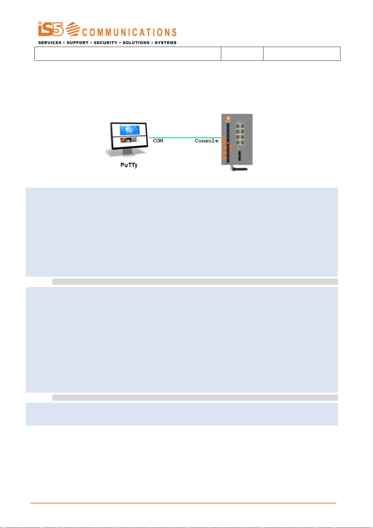
iSG18GFP User Manual R3.5
Ver: 1.3
Date: 04.28.2015
Install OS image update from a USB
Follow below steps as an example of uploading a desired OS image stored on a local USB key and activating it.
1. Access second safe mode, use option 4 “recover” and list the current OS images available at the switch.
-----------------------------------------------------------------------------------------
|safe mode menu:
| reset | 1 : Reset the device
| defcfg | 2 : Load the factory-default configuration for the device
| eeprom | 3 : Write to EEPROM
| recover | 4 : Recover the device's images from a package file
| db | 5 : Export / Import DB
| continue | c : Continue in start up process
| refresh | r : Refresh menu
| help | H : Display help about this utility
-----------------------------------------------------------------------------------------
#######################################################################
### Device Image Recovery #########################################
#######################################################################
usb | 1 : Download the package file from USB
ls | 2 : List the available application files
active | 3 : Change the active working application
show | 4 : Display the active working application
remove | 5 : Delete an application
free | 6 : Display the free space in the application file system
main | X : Return to the main menu
help | H : Display help about this menu
List of sw versions:
3.5.04.32 (active)
3.5.04.15
4
2
iS5 Communications Inc. Page: 51 of: 465

iSG18GFP User Manual R3.5
Ver: 1.3
Date: 04.28.2015
2. Delete the unused OS-Image file
-----------------------------------------------------------------------------------------
|safe mode menu:
| reset | 1 : Reset the device
| defcfg | 2 : Load the factory-default configuration for the device
| eeprom | 3 : Write to EEPROM
| recover | 4 : Recover the device's images from a package file
| db | 5 : Export / Import DB
| continue | c : Continue in start up process
| refresh | r : Refresh menu
| help | H : Display help about this utility
-----------------------------------------------------------------------------------------
#######################################################################
### Device Image Recovery #########################################
#######################################################################
usb | 1 : Download the package file from USB
ls | 2 : List the available application files
active | 3 : Change the active working application
show | 4 : Display the active working application
remove | 5 : Delete an application
free | 6 : Display the free space in the application file system
main | X : Return to the main menu
help | H : Display help about this menu
List of sw versions:
3.5.04.32 (active)
3.5.04.15
Enter version name
For main menu press X
Removing version 3.5.04.15
Version was deleted successfully
-----------------------------------------------------------------------------------------
|safe mode menu:
| reset | 1 : Reset the device
| defcfg | 2 : Load the factory-default configuration for the device
| eeprom | 3 : Write to EEPROM
| recover | 4 : Recover the device's images from a package file
| db | 5 : Export / Import DB
| continue | c : Continue in start up process
| refresh | r : Refresh menu
| help | H : Display help about this utility
-----------------------------------------------------------------------------------------
4
5
3.5.04.15
3. Download a new OS Image file from the usb. A list of available files at the usb will be displayed. Copy the complete file
name and path. Below examples relates to version 4.0.02.10.tar
4
#######################################################################
iS5 Communications Inc. Page: 52 of: 465

iSG18GFP User Manual R3.5
Ver: 1.3
Date: 04.28.2015
### Device Image Recovery #########################################
#######################################################################
usb | 1 : Download the package file from USB
ls | 2 : List the available application files
active | 3 : Change the active working application
show | 4 : Display the active working application
remove | 5 : Delete an application
free | 6 : Display the free space in the application file system
main | X : Return to the main menu
help | H : Display help about this menu
-rw-rw-rw- 1 root root 58112000 Jan 21 2014 /mnt/usb/IS_5018_3.5.04.15.tar
-rw-rw-rw- 1 root root 59494400 Apr 7 2014 /mnt/usb/IS_5018_3.5.04.31.tar
-rw-rw-rw- 1 root root 59555840 Jun 5 2014 /mnt/usb/IS_5018_3.6.04.24.tar
-rw-rw-rw- 1 root root 59842560 Jun 2 2014 /mnt/usb/IS_5018_4.0.02.10.tar
Enter version number on usb.
For main menu press X
/mnt/usb/IS_5018_4.0.02.10.tar
Version was installed successfully
-----------------------------------------------------------------------------------------
|safe mode menu:
| reset | 1 : Reset the device
| defcfg | 2 : Load the factory-default configuration for the device
| eeprom | 3 : Write to EEPROM
| recover | 4 : Recover the device's images from a package file
| db | 5 : Export / Import DB
| continue | c : Continue in start up process
| refresh | r : Refresh menu
| help | H : Display help about this utility
-----------------------------------------------------------------------------------------
#######################################################################
### Device Image Recovery #########################################
#######################################################################
usb | 1 : Download the package file from USB
ls | 2 : List the available application files
active | 3 : Change the active working application
show | 4 : Display the active working application
remove | 5 : Delete an application
free | 6 : Display the free space in the application file system
main | X : Return to the main menu
help | H : Display help about this menu
List of sw versions:
3.5.04.32 (active)
4.0.02.10
Enter version to activate
1
4. Activate the new version. The system will boot
4
3
iS5 Communications Inc. Page: 53 of: 465

iSG18GFP User Manual R3.5
Ver: 1.3
Date: 04.28.2015
For main menu press X
Updating bank1 with vmlinux.UBoot file, please wait ...
4.0.02.10
Installing First OS image from a USB
Follow below steps as an example of installing a first version from a usb. Local database and any active OS image will be
deleted. The system will boot with manufacturing defaults using the new OS imported file.
1. Access first safe mode, use option 4 “install”. Select the version to be used. the system will boot automatically to
-----------------------------------------------------------------------------------------
Safe mode requested from boot...
-----------------------------------------------------------------------------------------
|safe mode menu: |
| reset | 1 : Reset the device |
| format | 2 : Format flash |
| activate | 3 : Activate sw version on flash |
| install | 4 : Install first sw version from USB |
| other | o : write other type field |
| continue | c : Continue with start up process |
| help | H : Display help about this utility |
-----------------------------------------------------------------------------------------
!!!!!!!!!!!!!!!!!!!!!!!!!!!!!!!!!!!!!!!!!!!!!!!!!!!!!!!!!!!!!!!!!!!!!!!!!!!!!!!!!!!!!!!!!!!
!!!!!!!!!!!!!!!!!!!!!!!!! This choice will delete data from flash
!!!!!!!!!!!!!!!!!!!!!!!!!!!!!!
!!!!!!!!!!!!!!!!!!!!!!!!! Continue [y/n]
!!!!!!!!!!!!!!!!!!!!!!!!!!!!!!y
!!!!!!!!!!!!!!!!!!!!!!!!!!!!!!!!!!!!!!!!!!!!!!!!!!!!!!!!!!!!!!!!!!!!!!!!!!!!!!!!!!!!!!!!!y
-rw-rw-rw- 1 root root 58112000 Jan 21 2014 /mnt/usb/IS_5018_3.5.04.15.tar
-rw-rw-rw- 1 root root 59842560 Jun 2 2014 /mnt/usb/IS_5018_4.0.02.10.tar
Enter version number on usb.
For main menu press X
Veryfing sw version IS_5018_3.5.04.15.tar
bcm_sdk_iss_app.tar.gz: OK
SW version was verified successfuly
vmlinux.tar
vmlinux.UBoot: OK
Updating bank1 with vmlinux.UBoot file, please wait ...OK
activate the new OS.
4
/mnt/usb/IS_5018_3.5.04.15.tar
iS5 Communications Inc. Page: 54 of: 465

iSG18GFP User Manual R3.5
Ver: 1.3
Date: 04.28.2015
System Database Import/ Export
To import/ export system configuration database, access the second safe mode.
1. Access second safe mode, use option 4 “recover” and list the current OS images available at the switch.
-----------------------------------------------------------------------------------------
|safe mode menu:
| reset | 1 : Reset the device
| defcfg | 2 : Load the factory-default configuration for the device
| eeprom | 3 : Write to EEPROM
| recover | 4 : Recover the device's images from a package file
| db | 5 : Export / Import DB
| continue | c : Continue in start up process
| refresh | r : Refresh menu
| help | H : Display help about this utility
-----------------------------------------------------------------------------------------
-----------------------------------------------------------------------------------------
|safe mode menu:
| reset | 1 : Reset the device
| defcfg | 2 : Load the factory-default configuration for the device
| eeprom | 3 : Write to EEPROM
| recover | 4 : Recover the device's images from a package file
| db | 5 : Export / Import DB
| continue | c : Continue in start up process
| refresh | r : Refresh menu
| help | H : Display help about this utility
-----------------------------------------------------------------------------------------
4
2. At the sub menu, select option 5 “db”. Use option 3 to view available db files at the usb (for import). Below example
demonstrate importing a db file named “ss_spoke1” from the usb and booting the system with it.
3
List of db files on usb:
-rwxr-xr-x 1 root root 2503168 Jan 1 1980 ss_spoke1
-----------------------------------------------------------------------------------------
|safe mode menu:
| reset | 1 : Reset the device
| defcfg | 2 : Load the factory-default configuration for the device
| eeprom | 3 : Write to EEPROM
| recover | 4 : Recover the device's images from a package file
iS5 Communications Inc. Page: 55 of: 465

iSG18GFP User Manual R3.5
Ver: 1.3
Date: 04.28.2015
| db | 5 : Export / Import DB
| continue | c : Continue in start up process
| help | H : Display help about this utility
#########################################################
### Export / Import DB ###############################
#########################################################
export | 1 : Export DB to usb
import | 2 : Import DB from usb
list | 3 : Show list of db files on usb
main | X : Return to the main menu
help | H : Display help about this menu
Import Db from usb
Enter file name
-----------------------------------------------------------------------------------------
|safe mode menu:
| reset | 1 : Reset the device
| defcfg | 2 : Load the factory-default configuration for the device
| eeprom | 3 : Write to EEPROM
| recover | 4 : Recover the device's images from a package file
| db | 5 : Export / Import DB
| continue | c : Continue in start up process
| help | H : Display help about this utility
-----------------------------------------------------------------------------------------
…….
5
2
ss_spoke1
C
iS5 Communications Inc. Page: 56 of: 465

iSG18GFP User Manual R3.5
Ver: 1.3
Date: 04.28.2015
Command
Description
interface-type <>
Specify the interface type
Fastethernet
gigabitethernet
Port id <>
Specify the port id as slot number/port number
Slot number is constant0 (zero)
Port number is in the range of 0-16 (depended on the
hardware)
iSG18GFP variant of 8RJ45+2GSFP+6GCX
iSG18GFP variant of 8RJ45+2GSFP+8SFP
Port Interfaces
Port addressing
The ports are configured as <interface-type> <port id>
Graphical view of system Interfaces
iS5 Communications Inc. Page: 57 of: 465

iSG18GFP User Manual R3.5
Ver: 1.3
Date: 04.28.2015
NOTE
The RS 232 ports are configured and identified within the ACE CLI mode and
are not seen at “show vlan”. See chapter Serial Interfaces for more information.
NOTE
The iSG18GFP has several hardware ordering options of interfaces. The
Ethernet interfaces which are applicable to the hardware will be available for
configuration.
A logical view of ports
Below screen shots shown the available typical ports of a iSG18GFP with 8 Ethernet ports.
iS5 Communications Inc. Page: 58 of: 465

iSG18GFP User Manual R3.5
Ver: 1.3
Date: 04.28.2015
NOTE
System Default has all ports as enabled
Vlan id / port
Gi 0/3
Gi 0/4
Vlan 4092
Tagged
Vlan 4093
Tagged
Vlan 1
Tagged (pvid)
Tagged
NOTE
The ACE ports properties should not be changed from their default settings of
auto-negotiation and hybrid state.
Enabling Ports
In order to be accessible, the required interfaces must be activated. This is done using the no shutdown command.
Example of enabling port interface number 5
ACE Ports
iSG18GFP(config)# interface gigabitethernet 0/5
iSG18GFP(config-if)# no shutdown
iSG18GFP(config-if)# end
iSG18GFP# write startup-cfg
The show interfaces command displays the complete information of all available interfaces.
Ports Gigabitethernet 0/3 and Gi 0/4 are unique ports. These are internal system ports used for directing access and
network traffic handled at the GCE to the Application services.
The use of these ports should be made in accordance to configuration instructions given in relevant chapters of this
manual.
Default state
iS5 Communications Inc. Page: 59 of: 465

iSG18GFP User Manual R3.5
Ver: 1.3
Date: 04.28.2015
Networking / port
Gi 0/3
Gi 0/4
Serial tunneling
Service VLANs
Terminal Server
Service VLANs
Gateway
Service VLANs
L2 VPN
NNI Vlan
UNI Vlan
L3 VPN
NNI Vlan
IPsec
NNI Vlan
Cellular
Firewall
Service VLANs
NOTE
With hardware versions of ET28 these ports properties should not be changed
from their default settings of auto-negotiation and hybrid state.
Vlan assignment
The assignment of the ACE ports to a vlan is always as a tagged member.
Following table summarizes the ports vlan membership depending on the network planning.
Ports FE 0/9-0/16
The usage of ports FE 0/9 -0/16 is dependent on the hardware type.
With hardware versions of ET216 and ET288 these ports are standard user ports to be addressed and configured for all
application purposes.
With hardware versions of ET28 these ports are not physically available for the user but are still mapped in the cli.
At this case these ports are designated for internal system functions and should not be addressed by the user unless
specifically mentioned in a configuration setup of feature in this manual.
iS5 Communications Inc. Page: 60 of: 465

iSG18GFP User Manual R3.5
Ver: 1.3
Date: 04.28.2015
POE Ports
Depending on your hardware variant POE ports might be applicable.
Hardware supporting POE is named:
IS5-ISG18GFP-<P>-<T>/<E>/8PE30/<R>/<C> - hardware includes 8 POE support on the FE Ethernet ports 1-8. All POE ports
are wired as Alternative-A (PoE runs on the FE twisted pairs)
IS5-ISG18GFP-<P>-<T>/<E>/8PE302RW/<R>/<C> - hardware includes 8 POE support on the FE Ethernet ports 1-8. Ports 2
and 8 are wired as Alternative-B (PoE runs on the spare twisted pairs)
IS5-ISG18GFP-<P>-<T>/<E>/8PE304RW/<R>/<C> - hardware includes 8 POE support on the FE Ethernet ports 1-8. Ports
2,4,6,8 are wired as Alternative-B (PoE runs on the spare twisted pairs)
Power Management of POE
The 8 POE ports supports in total maximum power output of:
1. For 12Vdc powered units (IS5-ISG18GFP-24../PE) : 60w
2. For 24Vdc powered units (IS5-ISG18GFP-24../PE) : 80w
3. For 48Vdc powered units (IS5-ISG18GFP-48../PE) : 120w
4. For 110Vdc powered units (IS5-ISG18GFP-11../PE) : 100w
5. For AC powered units (IS5-ISG18GFP-AC../PE) : 120w
iS5 Communications Inc. Page: 61 of: 465

iSG18GFP User Manual R3.5
Ver: 1.3
Date: 04.28.2015
CAUTION
Alternate-B POE ports work in forced mode and provides constant power on the
twisted pair lines. Make sure to connect only adequate equipment to these ports
The 8 POE ports divided to 2 groups ,each group supports maximum power output of:
Modes of POE
1. For 12Vdc powered units (IS5-ISG18GFP-24../PE) : 30w
2. For 24Vdc powered units (IS5-ISG18GFP-24../PE) : 40w
3. For 48Vdc powered units (IS5-ISG18GFP-48../PE) : 60w
4. For 110Vdc powered units (IS5-ISG18GFP-11../PE) : 50w
5. For AC powered units (IS5-ISG18GFP-AC../PE) : 60w
6. The group division is as follows:
a. Group 1: p1,p2,p3,p6
b. Group 2: p4,p5,p7,p8
Alternative-A wired ports will supply POE power on demand. Non-POE equipment connected to such port is protected as it
will not receive power over the Fast Ethernet communication lines.
Alternative-B wired ports will supply POE power constantly (forced mode) when enabled.
iS5 Communications Inc. Page: 62 of: 465

iSG18GFP User Manual R3.5
Ver: 1.3
Date: 04.28.2015
Command
Description
Config terminal
Interface <type> <port id>
Enter the specific Interface.
only fastethernet ports are applicable.
Permissible values : Fastethernet <1-8>
Poe
No shutdown: port is POE enabled. (default)
Shutdown: port is POE disabled.
poe-power
Detect: POE will be available only upon negotiation
with a POE connected load device. (default)
Manual: POE will be available constantly.
Caution: connect only POE capable load
devices to ports which are in Manual mode.
note : ports which are hardware Alternate-B
must be in Manual mode.
show poe-status port <>
Show the POE state of the port.
Port number is in the range 1-8, relating to
fastethernet 1-8.
POE command Hierarchy
+ Root
+ config terminal
+ interface <type> <port id>
- poe-power { detect | manual }
- poe { shutdown | no shutdown }
- show poe-status port <1-8>
POE Commands Description
iS5 Communications Inc. Page: 63 of: 465

iSG18GFP User Manual R3.5
Ver: 1.3
Date: 04.28.2015
Controlling Ports
Storm Control
Sets the storm control rate for broadcast, multicast
Rate Limit Output
Enables the rate limiting and burst size rate limiting by configuring the egress packet rate of an interface and the no form of
the command disables the rate limiting and burst size rate limiting on an egress port
Ports command Hierarchy
+ Root
+ config terminal
+ interface <type> <port id>
- [no] alias DESCRIPTION
- [no] speed (10 | 100 | 1000 | auto)
- [no] duplex (auto | full | half)
- [no] switchport pvid <vlan ID>
- [no] switchport mode {access | trunk | hybrid}
- [no] switchport acceptable-frame-type {all | tagged |
untaggedAndPrioritytagged}
- [no] system-specific port-id <id>
- [no] snmp trap link-status
- [no] negotiation
- flowcontrol (receive | send) (desired | on | off)
- mtu <mtu-value>
- [no] shutdown
- [no] storm-control { broadcast |multicast | dlf } level <pps (1-250,000>
- [no] rate-limit output [rate-limit] [burst-limit]
- switchport unicast-mac learning limit <limit value(0-32767)>
- switchport unicast-mac learning { enable | disable }
clear interfaces [ <interface-type> <interface-id> ] counters
clear counters [ <interface-type> <interface-id> ]
- Show interfaces [<interface-type> <interface-id>] [vlan <vlan-id> ]
iS5 Communications Inc. Page: 64 of: 465

iSG18GFP User Manual R3.5
Ver: 1.3
Date: 04.28.2015
Command
Description
Config terminal
Interface <type> <port id>
Alias
Set a description name for the port.
Speed
Set manual speed to the port. Requires first disabling
‘negotiation’ at the port.
Default: negotiation enabled.
Duplex
Set port duplex as full | half | auto.
Default: full
switchport mode
Configures the mode of operation for a switch port.
This mode defines the way of handling of traffic for
VLANs.
Access: accepts and sends only untagged. This kind
of port is added as a member to specific VLAN only
and carries traffic only for the VLAN to which the
port is assigned.
This mode is allowed only if the port is not a tagged
member at any vlan.
The port property of “switchport acceptable-frame-
type” must be set to untagged AND priority Tagged”.
Trunk: accepts and sends only tagged frames. This
kind of port is added as member of all existing
VLANs and for any new VLAN created, and carries
traffic for all VLANs. The trunk port accepts untagged
frames too, if the “switchport acceptable-frame-
type” is set as “all”.
The port can be set as trunk port, only if the port is
not a member of untagged ports for any VLAN in the
switch.
Hybrid: Configures the port as hybrid port that
accepts and sends both tagged and untagged
frames.
Default: Hybrid
- Show interfaces <type> <port id>
- show interface mtu
- show interfaces status
- show interfaces counters
- show interfaces capabilities
- show vlan port config [port <type> <port id>]
- show running-config interface <type> <port id>
Port Commands Description
iS5 Communications Inc. Page: 65 of: 465

iSG18GFP User Manual R3.5
Ver: 1.3
Date: 04.28.2015
Command
Description
switchport pvid
The PVID represents the VLAN ID that is to be
assigned to untagged frames.
The packets are processed against PVID, if the
packets accepted at ingress is not having a tag.
Permissible range: 1-4000.
default: 1.
switchport acceptable frame-type
negotiation
Enables port auto negotiation of speed.
default: enabled
mtu frame size
This command configures the maximum
transmission unit frame size for all the frames
transmitted and received on all the interfaces in a
switch. The size of the MTU frame size can be
increased using this command. The value ranges
between 90 and 9216.
This value defines the largest PDU that can be
passed by the interface without any need for
fragmentation. This value is shown to the higher
interface sub-layer and should not include size of the
encapsulation or header added by the interface. This
value represents the IP MTU over the interface, if IP
is operating over the interface.
Note: Any messages larger than the MTU are divided
into smaller packets before transmission
Default : 1500
system-specific port-id <>
This command configures the system specific index
for the port. It provides a different numbering space
other than the IfIndex to identify ports. The value
ranges between 1 and 16384.
Default : 0.
[no] snmp trap link-status
This command enables trap generation on the
interface. The no form of this command disables
trap generation on the interface.
The interface generated linkUp or linkDown trap.
The linkUp trap denotes that the communication link
is available and ready for traffic flow. The linkDown
trap denotes that the communication link failed and
isnot ready for traffic flow.
Default : enable
flowcontrol
{ send | receive}
Send : Sets the interface to send flow control
packets to a remote device
Receive : Sets the interface to receive flow control
packets from a remote device
iS5 Communications Inc. Page: 66 of: 465

iSG18GFP User Manual R3.5
Ver: 1.3
Date: 04.28.2015
Command
Description
{ on | off |desired}
On : If used with receive allows an interface to
operate with the attached device to send flow
control packets .If used with send the interface
sends flowcontrol packets to a remote device if the
device supports it
Off : Turns-off the attached devices (when used with
receive) or the local ports (when used with send)
ability to send flow-control packets to an interface
or to a remote device respectively
Desired : Allows a local port to operate with an
attached device that is required
to send flow control packets or that may send the
control packets,
when used with receive option.
Allows the local port to send administrative status to
a remote device if the remote device supports it,
when used with send option.
storm-control
sets the storm control rate for broadcast, multicast
and DLF packets
broadcast - Broadcast packets
multicast - Multicast packets
dlf - Unicast packets
level - Storm-control suppression level as a total
number of packets per second. Permissible values :
1-250,000
rate-limit output
rate-value - Line rate in kbps
burst-value- Burst size value in kbps
clear interfaces [ <interfacetype> <interface-id> ] counters
clears all the current interface counters from the
interface
iS5 Communications Inc. Page: 67 of: 465

iSG18GFP User Manual R3.5
Ver: 1.3
Date: 04.28.2015
Port Configuration Example
1. Set a port speed to 100
iSG18GFP# config
iSG18GFP(config)# interface fastethernet 0/2
iSG18GFP(config-if)# no negotiation
iSG18GFP(config-if)# speed 100
2. Set a port as Trunk. Make sure to remove it from any vlan at which it is set as untagged member.
iSG18GFP(config)# Vlan 1
iSG18GFP(config-vlan)# no ports fastethernet 0/1 untagged fastethernet 0/1
iSG18GFP(config-vlan)# exit
iSG18GFP(config)# interface fastethernet 0/1
iSG18GFP(config-if)# switchport mode trunk
iSG18GFP(config-if)# switchport acceptable-frame-type all
3. Set a port PVID
iSG18GFP(config)# interface fastethernet 0/5
iSG18GFP(config-if)# switchport pvid 5
4. Set a Port Alias
iSG18GFP(config)# interface fastethernet 0/2
iSG18GFP(config-if)# alias Office-network
Configuration Output Example
iSG18GFP# show interfaces fastethernet 0/2
Fa0/2 up, line protocol is up (connected)
Bridge Port Type: Customer Bridge Port
Interface SubType: fastEthernet
Interface Alias: Office-network
Hardware Address is 00:20:d2:fc:c1:f1
MTU 1500 bytes, Full duplex, 100 Mbps, No-Negotiation
HOL Block Prevention disabled.
CPU Controlled Learning disabled.
Auto-MDIX on
Input flow-control is off,output flow-control is off
Link Up/Down Trap is enabled
iSG18GFP# show interfaces status
Port Status Duplex Speed Negotiation Capability
iS5 Communications Inc. Page: 68 of: 465

iSG18GFP User Manual R3.5
Ver: 1.3
Date: 04.28.2015
---- ------ ------ ----- ----------- ----------
Fa0/1 not connected Half - Auto Auto-MDIX on
Fa0/2 connected Full 100 Mbps No-Negotiation Auto-MDIX on
Fa0/3 not connected Half - Auto Auto-MDIX on
…
iSG18GFP# show vlan port config port fastethernet 0/1
Vlan Port configuration table
-------------------------------
Port Fa0/1
Bridge Port Type : Customer Bridge Port
Port Vlan ID : 1
Port Acceptable Frame Type : Admit All
Port Mac Learning Status : Enabled
Port Mac Learning Limit : Default
Port Ingress Filtering : Disabled
Port Mode : Trunk
…
iSG18GFP# show vlan port config port fastethernet 0/5
Vlan Port configuration table
-------------------------------
Port Fa0/5
Bridge Port Type : Customer Bridge Port
Port Vlan ID : 5
Port Acceptable Frame Type : Admit All
Port Mac Learning Status : Enabled
…
Login and Management
Configuring the Login Authentication Method sets the authentication method for user logins.
Setting up specific authorized personal for the switch management is possible using filtering conditions as: IP address
(mandatory), vlan-id and service type (SSH, Telnet, SNMP...)
Once an authorized personal is configured in the system, no other entity can have management to the switch over IP.
Serial console management remains available and not influenced by the authorized manager conditions.
If no authorized managers are configured (default state),then switch management is possible on all configured Vlans and
associated ports via the respective IP interfaces assigned.
Login Authentication Hierarchy
+ root
- lock
- logout
+ config terminal
-[no] authorized-manager ip-source <IP>
{<subnet> | <prefix-length>, interface <type> ,vlan <id> ,service <type> }
- login authentication [{ radius [local]| tacacs [local]}] [local]
iS5 Communications Inc. Page: 69 of: 465

iSG18GFP User Manual R3.5
Ver: 1.3
Date: 04.28.2015
- login authentication default
- login block-for <seconds(30-600)> attempts <tries(1-10)>
- show authorized-manager [ip-source < ip-address >]
- show system information
- show logging
- username <user-name> password [8-20 char] privilege <1-15>
- username <user-name> status [enable | disable]
- no username <user-name>
- show users
- show line
- listuser
- show privilege
iS5 Communications Inc. Page: 70 of: 465

iSG18GFP User Manual R3.5
Ver: 1.3
Date: 04.28.2015
Command
Description
Config terminal
authorized-manager ip-source
This command configures an IP authorized manager
and the no form of the command removes manager
from authorized managers list.
<ip-address>
Sets the network or host address from which the
switch is managed. An address 0.0.0.0 indicates 'Any
Manager'."
<subnet-mask>
Sets the subnet mask for the configured IP address.
The configured subnet mask should be in the same
subnet of the network in which the switch is placed.
<prefixlength(1-32)>
Configures the number of high-order bits in the IP
address.These bits are common among all hosts
within a network.
The value ranges between 1 and 32.
interface
vlan <>
Sets the list of VLANs or a single specific VLAN in
which the IP authorized manager can reside.
Service
Configures the type of service to be used by the IP
authorized manager. The values can be:
SSH | SNMP | HTTP | HTTPS
login authentication [{radius
| tacacs }] [local]
Radius : Sets the RADIUS server to be used as an
authentication server. Enables remote access
servers to communicate with a central server to
authenticate dial-in users and authorize their access
to the requested system or service.
Tacacs : Sets the TACACS server to be used as an
authentication server. Communicates with the
authentication server commonly used in networks.
Local : Sets locals authentication. The user
identification, authentication, and authorization
method is chosen by the local system administration
and does not necessarily comply with any other
profiles.
Default : local
Login Authentication Commands Description
iS5 Communications Inc. Page: 71 of: 465

iSG18GFP User Manual R3.5
Ver: 1.3
Date: 04.28.2015
Command
Description
[no] login authentication
default
default: Sets the default authentication method for
User Logins.
[no] username
Set a new user.
Username: should be 1-20 charaters length.
- Allowed small and capitol letters. - Allowed
numbers: 0-9
- Allowed special symbols: – and _
Password: should be 4-20 charaters length.
- Must include small letters.
- Must include capitol letter.
- must include number
- must include special symbol.
- allowed synbols: @#$%^&*()-+./<\`
Priviliege: 1-15.
show alias
Displays the aliases
iS5 Communications Inc. Page: 72 of: 465

iSG18GFP User Manual R3.5
Ver: 1.3
Date: 04.28.2015
Examples
1. configure user
iSG18GFP(config)# username company-ceo password User#123 privilege 15
2. example for assignment of authorized manager
iSG18GFP(config)# authorized-manager ip-source 10.10.20.20 / 32 interface
fastethernet 0/1 vlan 1 service ssh snmp telnet
iSG18GFP(config)# authorized-manager ip-source 10.10.10.10
iSG18GFP# show authorized-managers
Ip Authorized Manager Table
---------------------------
Ip Address : 10.10.10.10
Ip Mask : 255.255.255.255
Services allowed : SSH
Ports allowed : Fa0/1, Fa0/2, Fa0/3, Fa0/4
Fa0/5, Fa0/6, Fa0/7, Fa0/8
Gi0/1, Gi0/2, Gi0/3, Gi0/4
Fa0/9, Fa0/10, Fa0/11, Fa0/12
Fa0/13
On cpu0 : Deny
Vlans allowed : All Available Vlans
Ip Address : 10.10.20.20
Ip Mask : 255.255.255.255
Services allowed : SNMP, TELNET, SSH
Ports allowed : Fa0/1
On cpu0 : Deny
Vlans allowed : 1
3. example for blocking management to vlan 1
config
authorized-manager ip-source 0.0.0.1 / 32 vlan 1
iS5 Communications Inc. Page: 73 of: 465

iSG18GFP User Manual R3.5
Ver: 1.3
Date: 04.28.2015
Command
Description
VLAN Module status
Enable
Config
Username <user-name>
Specifies the login user name to be created
Privilege level
Privilege Levels can be determined in order to best allocate system accessibility to different users.
Total of 16 levels, numbered 0-15 can be configured.
By default, the root user holds privilege level 15, allowing complete system availability.
Privilege Level 0 is the lowest level, restricting the user to minimum system access.
Users with Privilege Level 0 can access only the following commands:
Users with Privilege Level 1 can access all user-level commands with iSG18GFP> prompt.
System allows to configure additional privilege levels (from level 2 to 14) to meet the needs of the users while protecting
the system from unauthorized access.
Users with Privilege Level 15 can access all commands. It is the least restricted level.
Enable
Disable
Exit
Help
logout
Commands Description
iS5 Communications Inc. Page: 74 of: 465

iSG18GFP User Manual R3.5
Ver: 1.3
Date: 04.28.2015
Command
Description
Password <passwd>
Specifies the password to be entered by the user to
login to the system.
Password must contain 8-20 characters and should
include at least one of each character type:
* special character
* alphabetic character
* numerical character
* uppercase character
* lowercase character
Special characters supported :
!@#$%^&*(){}[]/\`~+=
privilege <1-15>
Applies restriction to the user for accessing the CLI
commands. This values ranges between 1 and 15.
For example, a user ID configured with privilege level
as four can access only the commands having
privilege ID lesser than or equal to four
Serial Console Port
Management over the serial console port is enabled by default but can be blocked with the following command.
For the change in state to take effect the system must be rebooted.
Keep in mind to maintain management over IP interface prior to disabling the console port.
Connecting to the Console Port
The console port is an EIA232 VT-100 compatible port to enable the definition of the device's basic operational
parameters.
Connecting the device to a PC using the Console Port:
Connect the RJ-45 connector of the console cable to the device's Console Port (CON).
Connect the other side of the cable to the PC.
Configure the PC port to 9600-N-8-1 (9600 bps, no parity,8 data bits, 1 stop bit, no flow control)
iS5 Communications Inc. Page: 75 of: 465

iSG18GFP User Manual R3.5
Ver: 1.3
Date: 04.28.2015
RJ45 Male
DB9 Female
1 -
Rx 2 3
Tx 3 2
GND
4
5
GND
5
5
6 -
7 - 8
-
NOTE
The “cli console” takes effect only after system restart.
Below table details the console cable pin-out.
CLI Console Commands
This command enables the console CLI through a serial port. The no form of the command disables the console CLI.
+ root
- lock
+ config
- Show nvram
- logout
- [no] Cli console
+ line {vty |console}
- exec-timeout <timeout sec>
Management
The switch can be managed via following methods:
IP and Vlan based.
Serial console port.
HTTP page.
For Restrictions of users, privileges and authentications please see related chapters in this manual.
iS5 Communications Inc. Page: 76 of: 465

iSG18GFP User Manual R3.5
Ver: 1.3
Date: 04.28.2015
Feature
Default state
Vlan 1
Active. All ports are members
Layer 3 interface
Interface vlan 1 is set to : 10.0.0.1/8
SSH
Enabled
Telnet
Disabled
Http
Disabled
Console
Enabled
User
User name : su
Password : 1234
Privilege : admin (15)
Default state
Commands Hierarchy
+ root
- set host-name <[default | <name> ]
- set welcome-banner [ default | <”banner name”> ]
- set ssh-client { enable | disable }
- set telnet-client { enable | disable }
- ssh {<user>@<remote IP>}
- show iss memory all
- show iss-memory-leak modules
iS5 Communications Inc. Page: 77 of: 465
- telnet [user]@{remote IP}
- lock
- logout
- show running-config system
+ config terminal
+ line {vty |console}
- exec-timeout <timeout sec>
-[no] cli console
-[no] feature telnet
- set ip http [ enable | disable]
- ip http port <port-number(1-65535)>
+ interface <type> <port id>
- [no] switchport pvid <vlan ID>
- [no] shutdown
+ [no] interface vlan <vlan id>

iSG18GFP User Manual R3.5
Ver: 1.3
Date: 04.28.2015
Command
Description
set host-name
Set the switch name as shown in the root prompt.
Default name is “iSG18GFP”.
set welcome-banner
Set the welcome banner as shown at log in screen.
default is “Welcome IS5 Communications customer”.
if spaces are required, place the complete title in
double brackets.
ssh
The switch supports ssh client allowing It to open ssh
session to a remote partner.
User : user name to be logged in at the remote
partner.
Remote-ip : IP address of remote partner.
Config terminal
- [no] shutdown
+ ip address [dhcp | <ip-address> <subnet-mask>]
- [no] ip http port <port>
- set ip http
+ Application connect
+ reload
- schedule date-and-time YYYY-MM-DD,HH:MM:SS
- schedule every <180 – 604800 seconds >
- schedule time HH:MM:SS
- schedule in <0 – 604800 seconds >
- cancel
- show
- show ip interface
- show http server status
- show running-config interface vlan <vlan id>
- Show interfaces
- Show interfaces <type> <port id>
- show telnet server
- show vlan port config [port <type> <port id>]
- show running-config interface <type> <port id>
- show telnet-client
- show ssh-client
Commands Description
iS5 Communications Inc. Page: 78 of: 465

iSG18GFP User Manual R3.5
Ver: 1.3
Date: 04.28.2015
Command
Description
line vty
Set idle time out for telnet / ssh to the switch.
exec-timeout : given in seconds .
default : 300 seconds
[no] cli
This command enables the console CLI through a
serial port. The no form of the command disables
console CLI.
This command takes effect only on system restart.
[no] ip http port <port>
This command sets the HTTP port. This port is used
to configure the router using the Web interface.
port number : 1-65535.
Default : 80
set ip http {enable | disable}
Enable : Enables HTTP in the switch.
Disable : Disables HTTP in the switch
Default : enable
[no] feature telnet
This command enables the telnet service in the
system.
Application Connect
reload schedule date-and-time
Set specific date and time for switch reload.
Time format : YYYY-MM-DD,HH:MM:SS
configuration which was not committed will not be
available after reload!
reload schedule every
Set time interval for cyclic automatic system reload.
Permissible range in seconds is 180 – 604800.
configuration which was not committed will not be
available after reload!
reload schedule time
Set specific time for switch reload.
Time format : HH:MM:SS
configuration which was not committed will not be
available after reload!
reload schedule in
Set specific timer for next switch reload.
Permissible range in seconds is 180 – 604800.
configuration which was not committed will not be
available after reload!
reload cancel
Cancels all scheduled automatic reloads
reload show
Shows user set scheduled reloads
Example
Follow below configuration example for establishing management on a certain port/s using designated vlan and IP.
1. Create your vlan and assign ports. Port 0/1 is configured as untagged ,0/2 as tagged
iS5 Communications Inc. Page: 79 of: 465

iSG18GFP User Manual R3.5
Ver: 1.3
Date: 04.28.2015
Config
vlan 10
ports fastethernet 0/1-2 untagged fastethernet 0/1
exit
2. Enable the required ports
interface fastethernet 0/1
no shutdown
switchport pvid 10
map switch default
exit
interface fastethernet 0/2
no shutdown
switchport pvid 10
map switch default
exit
3. Create the IP interface to the vlan
interface vlan 10
shutdown
ip address 192.168.0.100 255.255.255.0
no shutdown
end
4. Create static route
Config
ip route 0.0.0.0 0.0.0.0 192.168.0.1 1
end
write startup-cfg
iS5 Communications Inc. Page: 80 of: 465

iSG18GFP User Manual R3.5
Ver: 1.3
Date: 04.28.2015
Command
Description
Config terminal
Alias
<replacement string>
Represents the string for which a replacement is
needed.
<token to be replaced>
Specifies an abbreviated/ short form of the
replacement string
show alias
Displays the aliases
System Alias
This command replaces the given token by the given string and the no form of the command removes the alias created
for the given string.
This is to allow easier names to be used for perhaps long cli command.
+ Root
+ Config terminal
- alias <replacement string> <token to be replaced>
- show alias
CLI Pagination
Some show commands for example might produce a long output. By default, the output will be interrupted after every
screen length pending with the notice “—more—“ to continue.
Options:
Pressing the ENTER key will progress the output by a single line.
Pressing the SPACE key will progress the output by a screen length.
Pressing the Q key will interrupt the output entirely.
Turning CLI pagination on/off iss available with following command:
iSG18GFP(config)# set cli pagination on
iSG18GFP(config)# set cli pagination off
An output example of a show command with pagination set to on:
iSG18GFP# show running-config
#Building configuration...
snmp trap syslog-server-status
!
no smtp authentication
!
!
iS5 Communications Inc. Page: 81 of: 465

iSG18GFP User Manual R3.5
Ver: 1.3
Date: 04.28.2015
queue 1 interface fastethernet 0/1 qtype 1 scheduler 1 weight 1 queue-type unicast
!
queue 3 interface fastethernet 0/1 qtype 1 scheduler 1 weight 1 priority 2 queue
-type unicast
!
--More—
MAC-Address Table (FDB)
Port Mac Learning and limit
The Administrator configures the Mac Learning Status of each port as enabled or disabled. By default, each port in the
bridge is allocated a limit on the number of Mac address that is learnt on that port. The Mac Learning Limit on each port
is also configurable. The Port Mac Learning Limit is applicable only for the dynamic learnt entries.
Commands Hierarchy
+ root
+ config terminal
- set mac-learning { enable | disable }
- unicast-mac learning limit <0-4294967295>
- mac-address-table aging-time <sec (300,10-1000000)>
- mac-address-table static unicast <MAC> vlan <vlan id> interface <type> <id>
- no mac-address-table static unicast <MAC> vlan <vlan id>
+ interface <type> <port id>
- switchport unicast-mac learning [enable | disable]
- switchport unicast-mac learning limit <limit value(0-100)>
- switchport unicast-mac learning { enable | disable }
- switchport ingress-filter
- multicast-mac limit <limit>
- clear fdb
- show mac-address-table
- show vlan port config
- show multicast-mac limit
iS5 Communications Inc. Page: 82 of: 465

iSG18GFP User Manual R3.5
Ver: 1.3
Date: 04.28.2015
NOTE
For MAC traffic to be learned with the proper vlan tag ,ingress-filtering must be
enabled on the interface. Otherwise will be learned at vlan 1.
IP traffic will be learned with the vlan tag by default.
Configuration Example
1. place a static entry
iSG18GFP# show mac-address-table
Switch default
Vlan Mac Address Type ConnectionId Ports
---- ----------- ---- ----------- -----
1 02:20:d2:fc:1c:95 Static Fa0/4
4092 02:20:d2:fc:1c:78 Static Gi0/3
4092 02:20:d2:fc:1c:79 Static Fa0/10
4092 02:20:d2:fc:1c:7a Static Fa0/11
Total Mac Addresses displayed: 4
iSG18GFP(config)# mac-address-table static unicast 02:20:d2:fc:1c:95 vlan 1 interface fastethernet 0/4
2. remove a static entry
iSG18GFP(config)# no mac-address-table static unicast 02:20:d2:fc:1c:95 vlan 1
IP ARP Table
The ARP (Address Resolution Protocol) cache timeout can be set in the system. Static entries are as well allowed to be
entered
Commands Hierarchy
+ root
+ config terminal
- arp timeout <seconds (7200,30-86400)>
- arp <ip address> <hardware address> Vlan <vlan-id(1-4094)>
- no arp <ip address>
- show ip arp [ { Vlan <vlan-id(1-4094)> | <interface-type> <interface-id> |<ip-
address> | <mac-address> |summary | information }]
iS5 Communications Inc. Page: 83 of: 465

iSG18GFP User Manual R3.5
Ver: 1.3
Date: 04.28.2015
Command
Description
Config terminal
Arp timeout <>
sets the ARP (Address Resolution Protocol) cache
timeout. The timeout defines the period an arp
entry remains in the cache. When a new timeout
value is assigned, it only affects the new arp entries.
All the older entries retain their old timeout values.
The timeout values can be assigned to dynamic arp
entries only. static arp entries remain unaltered by
timeout value.
timeout <seconds (30-86400)>
default : 7200
arp <ip address> <MAC> vlan <>
<ip address> : Defines the IP address or IP alias to
map to the specified MAC address.
<hardware address> : Defines the MAC address to
map to the specified IP
address or IP alias.
Vlan <vlan-id(1-4094)>
Commands Description
Configuration Example
1. Set timeout
iSG18GFP# show ip arp
VRF Id : 0
VRF Name: default
Address Hardware Address Type Interface Mapping
------- ---------------- ---- --------- -------
172.18.212.100 00:11:22:33:44:55 ARPA vlan1 Static
iS5 Communications Inc. Page: 84 of: 465
iSG18GFP# config
iSG18GFP(config)# arp timeout 50
2. Set static entry
iSG18GFP(config)# arp 172.18.212.100 00:11:22:33:44:55 Vlan 1
3. Output example

iSG18GFP User Manual R3.5
Ver: 1.3
Date: 04.28.2015
iSG18GFP# show ip arp information
ARP Configurations:
-------------------
VRF Name: default
Maximum number of ARP request retries is 3
ARP cache timeout is 50 seconds
iS5 Communications Inc. Page: 85 of: 465

iSG18GFP User Manual R3.5
Ver: 1.3
Date: 04.28.2015
VLAN
Virtual LAN (VLAN) technology, defined under the IEEE 802.1q specifications, allows enterprises to extend the reach of
their corporate networks across WAN. VLANs enable partitioning of a LAN based on functional requirements, while
maintaining connectivity across all devices on the network. VLAN groups network devices and enable them to behave as
if, they are in one single network. Data security is ensured by keeping the data exchanged between the devices of a
particular VLAN within the same network.
VLAN offers a number of advantages over traditional LAN. They are:
1. Performance
In networks with traffic consisting of a high percentage of broadcasts and multicasts, VLAN minimizes the possibility of
sending the broadcast and multicast traffic to unnecessary destinations.
2. Formation of Virtual Workgroups
VLAN helps in forming virtual workgroups. During this period, communication between the members of the workgroup
will be high. Broadcasts and multicasts can be restricted within the workgroup.
3. Simplified Administration
Most of the network costs are a result of adds, moves, and changes of users in the network. Every time a user is moved in
a LAN, recabling, new station addressing, and reconfiguration of hubs and routers becomes necessary. Some of these
tasks can be simplified with the use of VLANs.
4. Reduced Cost
VLANs can be used to create broadcast domains, which eliminate the need for expensive routers.
5. Security
Sensitive data may be periodically broadcast on a network. Placing only those users, who are allowed to access to such
sensitive data on a VLAN can reduce the chances of an outsider gaining access to the data. VLAN can also be used to
control broadcast domains, set up firewalls, restrict access, and inform the network manager of an intrusion.
VLANs of System Usage
The Vlan range of 4000-4093 should be left for system internal usage and should not be used or manipulated by the user
unless specifically indicated in this manual.
VLAN Range of NMS Usage
The IS5 Communications iSIM NMS uses a configurable range of Vlans for the creation and management of services.
The user should take notice to avoid manipulating NMS created Vlans.
VLAN Configuration Guidelines
VLAN is enabled in the switch by default.
The default VLAN 1- cannot be deleted in the switch, but the ports can be removed from it.
iS5 Communications Inc. Page: 86 of: 465

iSG18GFP User Manual R3.5
Ver: 1.3
Date: 04.28.2015
Command
Description
VLAN Module status
Enable
Default VLAN Id configured in the
switch
1
Mac address table aging time
300 seconds
Acceptable frame types
All (Accepts untagged frames or priority-tagged
frames or tagged frames received on the port)
Ingress filtering
Disabled
NOTE
If the port type is not explicitly specified as untagged, then all the ports are
configured to be of tagged port type allowing transmission of frames with the
specified VLAN tag.
NOTE
If PVID value has not been explicitly configured for a port, then PVID assumes
a default value of 1
Mapping of forwarding database identifier (FID) to VLANs is successful only when, VLAN learning mode is hybrid.
To configure a static unicast/multicast MAC address in the forwarding database, VLAN must have been
VLAN logically segments the shared media LAN, forming virtual workgroups. It redefines and optimizes the basic
Transparent Bridging functionalities such as learning, forwarding, filtering and flooding.
VLAN Default state
configured and member ports must have been configured for the specified VLAN.
It is not possible to configure a port as trunk, if the port is an untagged member of a VLAN.
Up to 1k Vlans may be configured simultaneously.
Vlan ports
Member ports represent the set of ports permanently assigned to the VLAN egress list. Frames belonging to the specified
VLAN are forwarded to the ports in the egress list.
The untagged setting allows the port to transmit the frames without a VLAN tag. This setting is used to configure a port
connected to an end user device.
iS5 Communications Inc. Page: 87 of: 465

iSG18GFP User Manual R3.5
Ver: 1.3
Date: 04.28.2015
NOTE
Adding port to a vlan using the command “ports <type>..” will remove all ports
from the vlan and associate only the detailed ports to the vlan.
Adding port to a vlan using the command “ports add <type>..” will add this port
to the vlan without affecting other port members of the vlan.
Enabling VLAN
A VLAN can be made active in two ways:
By adding a member port to a VLAN (refer section Configuring Static ) or
By using the VLAN active command.
Vlan command Hirarchy
+ root
+ config terminal
+ [no] vlan <vlan id>
- [no] ports <port type> <port IDs> [untagged <port type> <port IDs>]
- ports add <port type> <port IDs> [untagged <port type> <port IDs>]
- set unicast-mac learning { enable | disable | default}
- vlan active
- vlan unicast-mac learning limit <0-4294967295>
+ interface <type> <port id>
- [no] switchport pvid <vlan ID>
- port mac-VLAN
- mac-address-table static [unicast | multicast] <MAC> Vlan <id> recv port
<type> <port id> interface <type> <port id>
- switchport unicast-mac learning { enable | disable }
- switchport unicast-mac learning limit <0-4294967295>
+ interface vlan <vlan id>
- [no] shutdown
- ip address [dhcp | <ip-address> <subnet-mask>]
- Show vlan [brief | id <vlan-range> | summary ]
- show vlan device info
- show vlan port config [port <type> <port id>]
- show running-config vlan [<vlan id>]
- show mac-address table static [unicast | multicast ]
iS5 Communications Inc. Page: 88 of: 465

iSG18GFP User Manual R3.5
Ver: 1.3
Date: 04.28.2015
Configuration Example
1. Setting all ports of the iSG18GFP to vlan 1 as untagged members
config
vlan 1
ports fastethernet 0/1-8 untagged fastethernet 0/1-8
ports add gigabitethernet 0/1-2 untagged gigabitethernet 0/1-2
exit
interface fastethernet 0/1
no shutdown
switchport pvid 1
exit
interface fastethernet 0/2
no shutdown
switchport pvid 1
exit
interface fastethernet 0/3
no shutdown
switchport pvid 1
exit
interface fastethernet 0/4
no shutdown
switchport pvid 1
exit
interface fastethernet 0/5
no shutdown
switchport pvid 1
exit
interface fastethernet 0/6
no shutdown
switchport pvid 1
exit
interface fastethernet 0/7
no shutdown
switchport pvid 1
exit
interface fastethernet 0/8
no shutdown
switchport pvid 1
exit
interface gigabitethernet 0/1
no shutdown
iS5 Communications Inc. Page: 89 of: 465

iSG18GFP User Manual R3.5
Ver: 1.3
Date: 04.28.2015
switchport pvid 1
exit
interface gigabitethernet 0/2
no shutdown
switchport pvid 1
exit
end
write startup-cfg
2. Vlan configuration example
iSG18GFP# config terminal
iSG18GFP(config)# vlan 55
iSG18GFP(config-vlan)# ports fastethernet 0/1-4,0/7 untagged fastethernet 0/2,0/7
iSG18GFP(config-vlan)# end
3. Vlan configuration example
iSG18GFP# config terminal
iSG18GFP(config)# vlan 32
iSG18GFP(config-vlan)# vlan active
iSG18GFP(config-vlan)# ports fastethernet 0/1-8 untagged all
iSG18GFP(config-vlan)# end
4. Configuration example for static Unicast entry
configuring a Static Unicast Entry requires the VLAN to be configured and the member ports for that specified
VLAN must also be configured.
iSG18GFP(config)# mac-address-table static unicast 22:22:22:22:22:22 VLAN 2 recvport gigabitethernet 0/1 interface gigabitethernet 0/2
iS5 Communications Inc. Page: 90 of: 465

iSG18GFP User Manual R3.5
Ver: 1.3
Date: 04.28.2015
NOTE
Total limit of 64 subnets is supported at the routing table. Customer static and
dynamic entries in total should not exceed a total of 60 entries.
IP Interfaces
The iSG18GFP supports multiple layer 3 interfaces to be set for the purposes of:
An IP interface is always assigned to a vlan.
Depending on its purpose an interface will be set either at the Global Configuration Environment or at the Application
Configuration Environment.
GCE IP Interfaces
The GCE interfaces are usually used for:
Different Interfaces must be in different subnets.
Each interface can be assigned, and must be assigned, to a single VLAN.
A VLAN can only be assigned a single IP interface.
Static routing of GCE IP interfaces is immediate and requires no special configuration.
Routing.
Management.
Serial services.
1. IP Management to the switch (SSH, Telnet ,HTTP, SNMP, FTP)
2. Routing of access traffic using static entries or OSPF
Dynamic routing of GCE IP interfaces is supported with OSPF.
Commands Hierarchy
+ root
+ config terminal
- debug ip dhcp client all
- release dhcp vlan <>
+ interface vlan <vlan id>
- [no] shutdown
- ip address [dhcp | <ip-address> <subnet-mask>]
[no] ip route <destination ip address> <destination subnet mask>
<next hope ip> <distance>
- renew dhcp vlan <>
- show interfaces
iS5 Communications Inc. Page: 91 of: 465

iSG18GFP User Manual R3.5
Ver: 1.3
Date: 04.28.2015
NOTE
Configuring the IP address for an Interface requires the interface to be shutdown
prior to the configuration.
Command
Description
Config terminal
Interface vlan <>
ip address
This command sets the IP address for an interface.
The no form of the command resets the IP address
of
the interface to its default value.
<ip address>
Sets the IP address for an interface. If the network in
which
Default : 172.18.212.150
<subnet mask>
Sets the subnet mask for the configured IP address.
The configured subnet mask should be in the same
subnet of the network in which the switch is placed.
Default : 255.255.255.0
[no] shutdown
Disable / enable the interface.
Prior to any configuration changes to the interface it
must first be disabled.
[no] ip route
This command adds a static route. The Route defines
the IP address or interface through which the
destination can be reached. The no form of this
command deletes a static route.
<destination ip address>
A.B.C.D
<destination mask>
Format 255.255.255.255
<next hop ip address>
Defines the IP address or IP alias of the next hop that
can be used to reach that network.
A.B.C.D
- show ip interface [vlan <vlan id>] [loopback <loopback id>]
- show running-config interface vlan <vlan id>
- show ip route [ { <ip-address> [<mask>] | connected |ospf | rip | static | summary } ]
- show debugging
- show ip dhcp client stats
- show ip dhcp server binding
- show running-config ip
Commands Description
iS5 Communications Inc. Page: 92 of: 465

iSG18GFP User Manual R3.5
Ver: 1.3
Date: 04.28.2015
Command
Description
<distance>
(1-254)
NOTE
Interface vlan 1 is available by default for In-band management.
NOTE
Interface vlan 4093 is used for internal purposes and should not be deleted
/changed.
Default state
iSG18GFP# show ip interface
vlan1 is up, line protocol is up
Internet Address is 10.0.0.1/8
Broadcast Address 255.255.255.255
vlan4093 is up, line protocol is up
Internet Address is 7.7.7.4/29
Broadcast Address 7.7.7.7
Configuration Examples
3180# show ip interface
vlan1 is up, line protocol is up
Internet Address is 172.17.203.39/24
1. Example for interface configuration
3180#config
interface vlan 10
ip address 192.168.0.100 255.255.255.0
no shutdown
end
write startup-cfg
2. Static route configuration
Config
ip route 0.0.0.0 0.0.0.0 192.168.0.10 1
end
write startup-cfg
3. Dhcp configuration
config
interface vlan 1
ip address dhcp
end
iS5 Communications Inc. Page: 93 of: 465

iSG18GFP User Manual R3.5
Ver: 1.3
Date: 04.28.2015
Command
Description
Config terminal
default mode
manual | dynamic
manual - Assigns static IP address to the default
interface. The IP address and IP mask configured by
user are assigned to the default interface.
dynamic - Assigns dynamic IP address to the default
interface. That is, IP
address provided by the server in the network is
assigned to the default interface on switch reboot.
The IP address is fetched through the dynamic IP
address configuration protocols such as DHCP client.
Default : manual
Default ip address
<ip address>
Sets the IP address for the default interface /
specified interface. If the network in which the
switch is
implemented contains a server such as DHCP server,
dynamically allocating IP address, the configured IP
address should not be within the range of the
addresses that will be allocated by the server to the
other switches.
This precaution avoids creation of IP address
conflicts between the switches.
Default : 10.0.0.1
Broadcast Address 172.17.203.255
IP address allocation method is dynamic
IP address allocation protocol is dhcp
Static & Dynamic switch Default IP Address assignment
+ root
+ config terminal
+ default mode [dynamic | manual]
+ default ip address <ip-address> [ subnet-mask <subnet mask> ]
[ interface <interface-type> <interface-id> ]
show nvram
+ default ip allocation protocol dhcp
iS5 Communications Inc. Page: 94 of: 465

iSG18GFP User Manual R3.5
Ver: 1.3
Date: 04.28.2015
Command
Description
subnet-mask <subnet mask>
Sets the subnet mask for the configured IP address.
The configured subnet mask should be in the same
subnet of the network in which the switch is placed
Default : 255.0.0.0
<interface-type>
fastethernet | gigabitethernet
<interface-id>
ID : <slot number>/<port number>
Slot number is fixed as 0.
default ip allocation protocol
dhcp
Allows the client device to obtain configuration
parameters such as network address, from the DHCP
server.
Default : dhcp
iS5 Communications Inc. Page: 95 of: 465

iSG18GFP User Manual R3.5
Ver: 1.3
Date: 04.28.2015
ACE IP Interfaces
The following services require assignment of an IP interface and possibly routes at the Application Configuration
Environment.
Multiple IP interfaces are optional.
The Application IP interfaces are supported on top of the layer 3 interfaces configured at the GCE and may be routed with
them.
Application IP interfaces are required for the following:
- Each IP interface must be associated with a user predefined VLAN (set at the GCE).
- Each interface must be associated with a “purpose”.
Serial tunneling
Terminal server
Protocol gateway
L2-VPN
L3-DMVPN
IPSec
o One (and only one) of the interfaces must be set to purpose application-host
- At each such purpose vlan, the ACE port Gi 0/3 must be set as a tagged member.
- Each interface must be in a unique subnet.
- The IP interfaces are given an automatic name indicating the vlan tag they are created with. The name format is:
ACE IP Interface Commands Hierarchy
+ root
+ configure terminal
o All other interfaces must be set to purpose general
ETH1.<vlan id>
+ application connect
+ router
- interface {create | remove} address-prefix <IP address>/<netmask>
vlan [vlan id] purpose {application-host |general}
- static {enable | dissable}
- ip route static <dest network> /<subnet> <Gateway>
- interface show
iS5 Communications Inc. Page: 96 of: 465
- route show

iSG18GFP User Manual R3.5
Ver: 1.3
Date: 04.28.2015
Command
Description
Application connect
Enter the industrial application menu
Router
Enter the application router configuration mode
interface
create | remove
Add or Remove an IP interface for the application
engine. The configuration should include:
Address-prefix : IP address in the format
aa.bb.cc.dd/xx
VLAN : vlan ID that the application engine will use
for this IP interface
The interface will be name eth1.<vlan id>
Static
Managing static route entries
Enable
Disable
Configure terminal
ip route static
dest network: target network address in the
format aa.bb.cc.dd/xx
Gateway : IP address in the format aa.bb.cc.dd
Show
Show ACE IP interfaces
Route show
Show ACE static route entries
ACE IP Interface Commands Description
Example for creating ACE IP Interface
1. Create a vlan to be used for interface.
port gigabitethernet 0/3 is mandatory to be assigned as tagged.
iSG18GFP#config
vlan 100
ports add gigabitethernet 0/3
end
write startup-cfg
2. Create an IP interface and static route (default gateway).
iSG18GFP#application connect
[/] router interface create address-prefix 172.17.212.10/24 vlan 100 purpose
application-host
[/]commit
[/]commit ok
iS5 Communications Inc. Page: 97 of: 465

iSG18GFP User Manual R3.5
Ver: 1.3
Date: 04.28.2015
[/]router interface show
+------+----------+------------------+------------------+-------------+
| VLAN | Name | IP/Subnet | Purpose | Description |
+======+==========+==================+==================+=============+
| 100 | eth1.100 | 172.17.212.10/24 | application host | |
+------+----------+------------------+------------------+-------------+
[/]router route show
Kernel IP routing table
Destination Gateway Genmask Flags Metric Ref Use Iface
172.17.212.0 0.0.0.0 255.255.255.0 U 0 0 0 eth1.100
0.0.0.0 172.17.212.100 0.0.0.0 UG 0 0 0 eth1.100
Completed OK
[router/] static
router/static> enable
router/static# configure terminal
router/static(config)# ip route 0.0.0.0/0 172.17.212.100
router/static(config)# write
router/static(config)# exit
router/static# exit
commit
Diagnostic
System Environment
Environment Command Hierarchy
+ Root
+ config terminal
- set switch maximum { RAM | CPU | flash } threshold <percentage>
- set switch temperature {min|max} threshold <celsius>}
+ interface <type> <port id>
- [no] snmp trap link-status
- show system information
- show env {all | temperature| RAM | CPU | flash | power}
- show nvram
iS5 Communications Inc. Page: 98 of: 465

iSG18GFP User Manual R3.5
Ver: 1.3
Date: 04.28.2015
Command
Description
Config terminal
Interface <type> <port id>
[no] snmp trap link-status
This command enables trap generation on the
interface. The no form of this command disables
trap generation on the interface.
The interface generated linkUp or linkDown trap.
The linkUp trap denotes that the communication link
is available and ready for traffic flow. The linkDown
trap denotes that the communication link failed and
isnot ready for traffic flow.
set switch maximum
This command sets the switch maximum threshold
values of RAM, CPU, and Flash. When the current
resource usage rises above the threshold limit, the
SNMP trap message with maximum severity will be
sent for the specified resource and the sntp message
will be displayed. This threshold value is represented
in percentage and ranges between 1 and 100
percentage
{ RAM | CPU | flash }
RAM : Indicates the maximum RAM usage of the
switch in percentage to trigger a trap.
CPU : Indicates the maximum CPU usage of the
switch in percentage to trigger a trap.
Flash : Indicates the maximum flash usage of the
switch in percentage to trigger a trap.
threshold <percentage>
Percentage : 1-100
Default : 100
set switch temperature
This command sets the maximum and minimum
temperature threshold values of the switch in
celcius.
When the current temperature drops below the
threshold, an SNMP trap with maximum severity will
be sent to the manager. This threshold value ranges
between -14 and 40 degree Celsius.
{min|max}
Sets the minimum /maximum temperature
threshold value for the switch to trigger a trap.
Defaults :
Minimum : 10 degree Celsius
Maximum : 40 degree Celsius
threshold <celsius>}
Environment Commands Description
iS5 Communications Inc. Page: 99 of: 465

iSG18GFP User Manual R3.5
Ver: 1.3
Date: 04.28.2015
Command
Description
Config
Set rmon
Enable: Enables the RMON feature in the system. On
enabling, the RMON starts monitoring the networks
both local and remote and provides network fault
diagnosis
Disable: Disables the RMON feature in the system.
On disabling, the RMON‟s network monitoring is
called off.
Default :disabled
Interface <type> <id>
rmon collection stats
This command enables history collection of interface
statistics in the buckets for the specified time
interval. The no form of the command disables the
history collection on the interface
<index (1-65535)> : Identifies an entry in the alarm
table. The value ranges between 1 and 65535.
Owner: Allows the user to enter the name of the
owner of the RMON group of statistics.
RMON
RMON (Remote Monitoring) is a standard monitoring specification that enables various network monitors and console
systems to exchange network-monitoring data.
The RMON specification defines a set of statistics and functions that can be exchanged between RMON-compliant
console managers and network probes. As such, RMON provides network administrators with comprehensive networkfault diagnosis, planning, and performance-tuning information.
Commands Hierarchy
+ root
+ config
- set rmon {enable | disable}
+ interface <type> <id>
- rmon collection stats <index (1-65535)> [owner <ownername (127)>]
- show rmon [statistics [<stats-index (1-65535)>]] [alarms] [events] [overview]]
- show running-config rmon
Commands Description
iS5 Communications Inc. Page: 100 of: 465
 Loading...