

Page 1

Page 2

2
Contents
1. Introduction............................................................................................................................. 4
1.1. Document description.....................................................................................................................4
1.2. Service data................................................................................................................................... 4
1.3. Safety rules....................................................................................................................................4
2. General Information................................................................................................................ 5
2.1. Purpose.......................................................................................................................................... 5
2.2. Set................................................................................................................................................. 5
2.3. Features......................................................................................................................................... 5
2.4. Appearance....................................................................................................................................7
2.5. Interfaces....................................................................................................................................... 8
2.5.1. Plug-in terminal connector.......................................................................................................8
2.6. Power connector............................................................................................................................. 9
2.6.1. Digital connector................................................................................................................... 10
2.7. Modem status display...................................................................................................................11
3. Functional diagram and operation description................................................................... 12
3.1. Functional diagram....................................................................................................................... 12
3.2. Operation description.................................................................................................................... 12
3.3. Watchdog timer types...................................................................................................................13
4. Connecting and configur ing................................................................................................. 14
4.1. Connecting................................................................................................................................... 14
4.2. Control, rebooting and connecting.................................................................................................14
4.3. Men u mod e.................................................................................................................................. 15
4.4. Pro g ra mming mode......................................................................................................................18
5. Creating, installing and deleting of Java-applications....................................................... 21
6. Emergencies..........................................................................................................................24
6.1. Emergency 1 (incorrect input power supply).................................................................................. 24
6.2. Emergency 2 (incorrect module power supply).............................................................................. 24
6.3. E mergency 3 (GSM module failed to start).................................................................................... 24
7. Support..................................................................................................................................25
Page 3

3
Tables
Table 2.5.1: Using terminal connector pins........................................................................................8
Table 2.5.2: Using connector power pins........................................................................................... 9
Table 2.5.3: Using digital connector pins.........................................................................................10
Table 2.6.1: Connection status diplay (green LED)..........................................................................11
Table 2.6.2: Emergency display (red LED) ......................................................................................11
Figures
Fig. 2.4.1. Front view......................................................................................................................... 7
Fig. 2.4.2. Back view..........................................................................................................................7
Fig. 2.5.1. Plug-in terminal connector.................................................................................................8
Fig. 2.5.2. Power connector...............................................................................................................9
Fig. 2.5.3. Digital connector............................................................................................................. 10
Fig. 3.1.1. Functional diagram of the modem...................................................................................12
Fig. 4.4.1. «My Computer» window o f Windows XP................................. ........................................21
Fig. 4.4.2. COM-port selecting......................................................................................................... 21
Fig. 4.4.3. Working with «Module» Disk...........................................................................................22
Fig. 4.4.4. General view of «AutoExec»...........................................................................................23
Page 4

4
1. Intr oduction
1.1. Document description
This manual is intended f or experi enced PC users. It describes the d evice and t he operati on of the G SM
modem iRZ TC65i-485GI.
1.2. Service data
Document version Issue date
2.11 09.20.2013
Prepared by V.N. Golovin Approved by P.A. Kosolapov
1.3. Safety rules
Restrictions on the use of the device near other electronic devices:
Turn the modem off in hospitals or when located near medical equipment such as pacemakers, hearing
aids and so on. Interference for medical equipment may occur
Turn the terminal off when on an airplane. Take measures to avoid accidental turning on
Turn the modem off in the vicinity of gas stations, chemical plants, and places where demolition work is
conducted. Interference for technical devices may occur
At a close range, the modem may produce interference for television sets and radio transmitters
Maintenance requirements:
Protect the modem against external hazards (high temperatures, caustic chemicals, dust, water and so
on)
Keep the modem safe from blows, falls, and strong vibrations
Do not attempt to take apart or modify the modem on your own. Such actions will void your warranty
Note: Make sure you follow the operation manual for this device. Im proper use of the device will disqualify
your warranty.
Page 5

5
2. Gen eral Information
2.1. Purpose
iRZ TC65i-485GI is an industrial GSM modem for receiving and transmitting data, text messages and
faxes. It is perfectly suited both for providing mobile access to the Internet and for industrial applications
including t elemetry, wireless data collection from sensors, remote monitoring, control, and signaling.
Built-in J ava platform, ADC and di gital inputs/out puts allow integrat ing the modem into a wide vari ety of
solutions. The m odem is controll ed by standard AT -commands. T he device is equipped wi th LEDs to m onitor
connection status and signal for emergency.
2.2. Set
The set of the GSM modem iRZ TC65i-485GI includes:
iRZ TC65i-485GI modem;
Mounting brac ket for attaching to a din-rail;
Factory package.
2.3. Features
Key features:
Frequency ranges: GSM 850/900/1800/1900MHz ;
Output power:
2W (class 4 f or EGSM850);
2W (class 4 f or EGSM900);
1W (class 1 f or GSM1800);
1W (class 1 f or GSM1800);
GPRS class 12;
TCP/I P stack accessed v ia AT-comm ands;
MS class B;
CSD up t o 14.4kbps;
USSD;
SMS;
Fax group 3, class 1;
Open pl atform for the development of Java appli cations;
Java parameters:
CLDC 1.1 HI;
J2ME with IMP 2.0 support;
secured data transferring with HTTP S and PKI support;
TCP, UDP, HTTP, FTP, SMTP, POP3 support;
rem ot e java-applicati on update (OTAP);
Page 6

6
Power characteristics:
Power supply f rom 9 to 28V
Consumpti on current not ex ceeding:
with the supply voltage of + 12V — 400mА;
with the supply voltage of + 24V — 200mА;
Physical characteristics:
Dim ensions not ex ceeding 76х85х30 mm;
Weight not exceeding 130g;
Operating temperat ures from -30°С to +65°С;
St orage tem peratures from -40°С to +75°С;
Interfaces:
TJ6-6P6C for RJ12 power connect or for powering the modem including 2 keys to “ground” and 2 ADC
channels;
TJ6-6P6C for RJ12 digital connector with 4 digit al inputs/outputs, output +3.3V, “ground”;
Pl ug-in terminal connector for powering the m odem, connecting the communication cable with RS485
interface;
SMA Jack for connecting the GSM antenna.
The device can be powered using either of the first two connectors.
Page 7
7
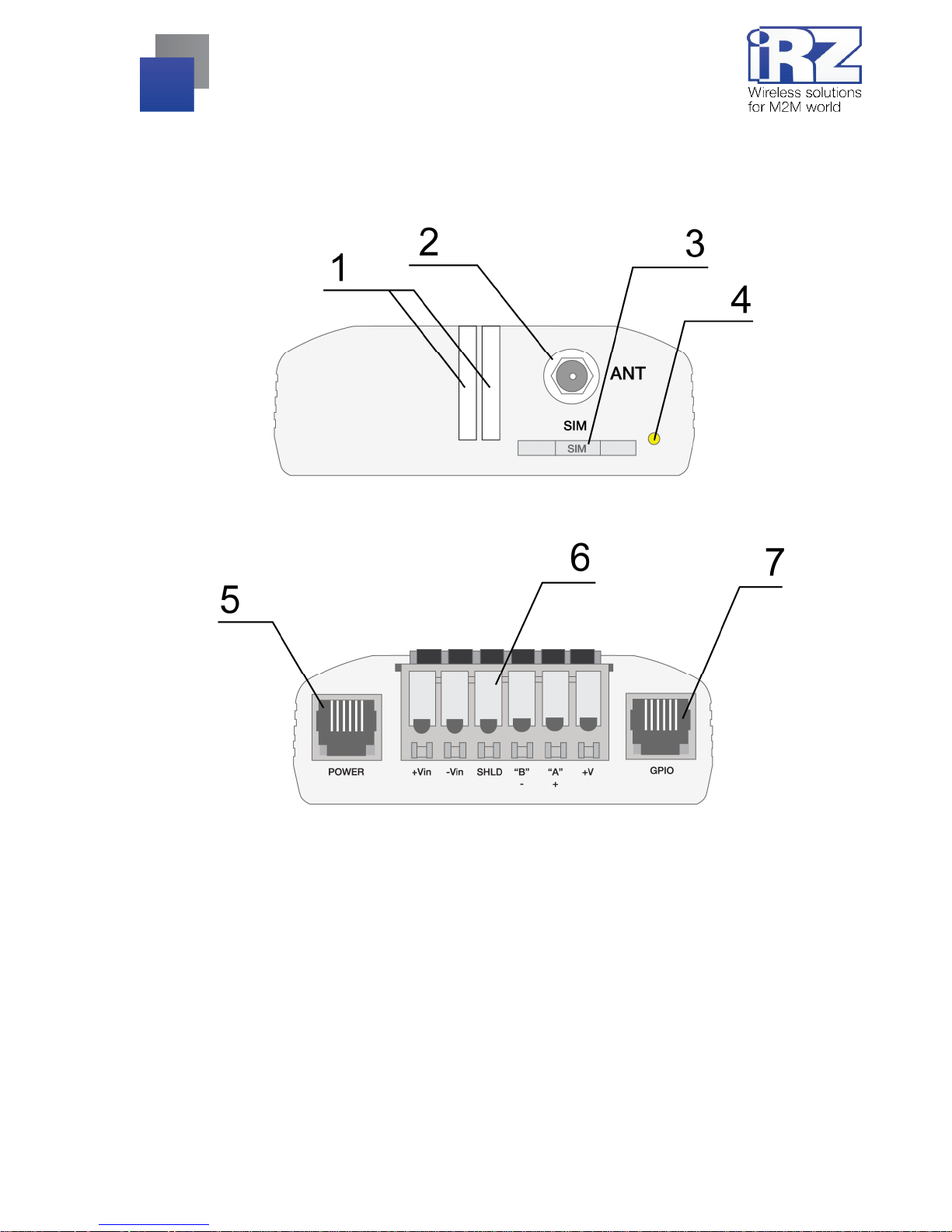
2.4. Appearance
TC65i-485GI m odem is a compact dev ice in an al uminum case. I ts appearance is di splayed on Fi g. 2.4.1
and Fig. 2.4.2.
Fig. 2.4.1. Front view
Fig. 2.4.2. Back view
The numbers on Fig. 2. 4.1 and Fig. 2.4.2 stand for:
1. LEDs (Emergency and Net work);
2. SMA connector for connecting the GSM antenna;
3. SIM-card tray;
4. SIM-card tray ejector button;
5. Power connector;
6. Plug-in terminal connector;
7. Digital input/output connector (GPIO).
Page 8

8
2.5. Interfaces
2.5.1. Plug-in terminal connector
This connector i s used for comm unication with a cont rolling devi ce, interface RS485. The AT -commands
are used to control the modem operation (see the module description).
Factory settings
: Speed: 115200 bps, Data Bit: 8, Parity: None, Stop Bit: 1.
Fig. 2.5.1. Plug-in terminal connector
Table 2.5.1: Using terminal connector pins
Pins Signal Purpose
1 +Vin “+” modem power supply
2 -Vin “-” modem power supply
3 SHLD “Shield” of RS48 5 interface
4 “B” “d-“ of RS485 interface;
inverse differential I/O
5 “A” “d+“ of RS485 interface;
direct differential I/O
Interface lines are protected by self-healing fuses and a
circuit of impulse noise suppression, as well as
overvoltage protection
6 +5V Output ”+5V” (RS485), 100mA (to power external devices)*
*For instance, it might be used to p ower RS485 interface of heat and electricity counters, etc.
Notes: RS485 interface i s half duplex. It needs t o be considered in case of data transf er. When echo i s
enabled, data i s sent to the modem will return. This can lead to col lision. In thi s case we recommend t o
disable echo (AT-command ate0).
Page 9

9
2.6. Power connector
TJ6-6P6C for RJ 12 power connector is used to power the device. Also displayed on Fig. 2.5.2 are two keys
to the “ground” and t wo ADC channels.
Fig. 2.6.1. Power connector
Table 2.6.1: Using connector power pins
Contact Signal Purpose
1 + 12V The positive pole of DC supply voltage. Fused circuit and overvoltage
protection (when input vol tage of over 30V is applied) and reverse polarity
2 Output of the “dry
contact” type to the
ground
Controlled by GPIO4 module output. When “logical 1” exits from the module
output, the “dry contact” output shortens to the “ground”
3 ADC2 Analog to digital converter. Parameters of the input circuit include input
resistance of 180kOhms and input voltage divider by 10. Connected to the
ADC2 pin of the GSM module
4 ADC1 Analog to digital converter. Parameters of the input circuit include input
resistance of 180kOhms and input voltage divider by 10. Connected to the
ADC1 pin of the GSM module
5 Output of the “dry
contact” type to the
ground
Controlled by GPIO5 module pin. When “logical 1” exits from the module
output, the “dry contact” output shortens to the “ground”
6 GND Ground
Output of the “ dry contact” type goes thr ough a 10 Ohm resistor to the col lector of the BC817 t ransistor.
The output of the GSM modul e goes to the transistor bas e. The emit ter of the t ransistor is connected t o the
“ground”. The m aximum current of the “dry contac t” output is 80mA.
Page 10

10
2.6.1. Digital connector
The connector has 4 digital pins. Both inputs and outputs can be used, which is specified in the GSM
module setti ngs.
Fig. 2.6.2. Digit al connector
Table 2.6.2: Using digital connector pins
Contact Signal Purpose
1 GND Body of the system or “ground”
2 GPIO2 Digital output controlling pin of GPIO2 module
3 GPIO1 Digital output controlling pin of GPIO1 module
4 GPIO10 Digital output controlling pin of GPIO10 module
5 GPIO3 Digital output controlling pin of GPIO3 module
6 +V +3.3V voltage of the modem
Parameters:
VOL
max
=0.2V, I=2mA;
VOH
min
=2.5V, I=-0.5mA;
VOH
max
=3.0V;
VIL
max
=0.8V;
VIH
min
=2.2V;
VIH
max
=3.0V.
The input/ output resistance of digital pins is 1kO hm. In order to send t he controlling si gnals to the di gital
pins it is recommended to use the first and the sixth pins of the connector.
Page 11

11
2.7. Modem status display
Two LEDs indicate current working mode (connection status) or signal for an emergency. This function can
be controlling by a corresponding AT-command (AT^SSYNC=1 — LED mode on; AT^SSYNC=0 — LED mode
off). By default, AT^SSYNC=1.
Table 2.7.1: Connection status diplay (green LED)
Display mode Conventional indication
display
Operation mode
Turned off
○
Modem is turned off or is in the emergency
status
600ms on / 600ms off
●●●●●●○○○○○○
Modem has not been registered online
75ms on / 3s off
●○○○○○○○○○...○
Modem has been registered online
75ms on / 75ms off /
75ms on / 3s off
●○●○○○○○○○...○
GPRS connection has been established
500ms on / 50ms off
●●●●●○
Data transmission is under way
250ms on / 10s off
●●●○○○○○○○...○
Modem is in the sleep mode, alarm clock mode
250ms on / 250ms off
●●●○○○
Programming mode, menu mode
Permanently turned on
●
Voice call, CSD
Configurations of display mode wit h "AT^SSYNC=2" and "AT^SSYNC= 1" is differ onl y by power saving
mode. For more information, see GSM module documentation.
Table 2.7.2: Emergency display (red LED)
Display mode Conventional indication
display
Emergency descript ion
Permanently turned on
●
Invalid input voltage
0.5s on / 0.5s off
●●○○
Invalid module power supply
0.25s on / 0.25s off /
0.25s on / 1s off
●○●○○○○
GSM module has not launched
Page 12

12
3. Functi onal diagr am and operati on descri ptio n
3.1. Functional diagram
The functional diagram of the modem is displayed on Fig. 3.1.1.
Fig. 3.1.1. Functional diagram of the modem
3.2. Operation description
The operation mode of the modem changes depending on the presence of the SIM-tray. When the SIM-tray
is install ed, the modem is i n the operat ion mode m eaning that the pi ns of the RS485 i nterf ace of t he umbilical
connector are wired t o t he UART 0 of t he GSM m odul e, UART of the managi ng micr ocont roll er is connec ted to
the UART1 of the GSM module, and the GSM module is tuned on.
In case the SIM- tray is mi ssing the m odem i s either in the progr ammi ng mode (the SIM- tray was removed
before powering the modem) or the menu mode (the SIM-tray was removed after powering the modem). In both
cases the GSM m odem is turned of f (t he modem’s power is shut down), and the RS4 85 int erface pins of the
umbilical connector are wired to the UART of the managing microcontroller.
The programmi ng mode allows updating t he software of the m anaging microcontroller. T he menu mode
allows changing the m odem’s parameters and access the statistics.
Page 13

13
The modem can be powered using either of the two connectors: the power connector or the umbilical
connector.
3.3. Watchdog timer types
Several types of watchdog timers are provided in the GSM modem:
Built-in watchdog tim er in the managi ng microcontroller. The m icrocontroller it self is m onitored for a
possibility of software crash (It is permanent ly on and cannot be turned off);
A regul ar check by t he m anaging microcontroller for a possibility of the GSM module deadlock of the
Java-appli cation. The interval can be set by the u ser in the range f rom 1 to 255 mi nutes in 1 minut e
increments. T he principle of i ts operation im plies that the managi ng microcont roller periodically sends
the “at” command ( speed 115200b/s, 8-N-1) to t he second COM-port of the module and wai ts for a
response “at”, then “OK”. Also, after each command, there should be “\r=CR \n=LF”. The response
should be analogou s to the response of the module wit hout the Java-appli cation wit h enabled echo. If
no response is received t he GSM module reboot s. The m odule’s power in t he meantim e is shut do wn.
This function can be activated or deactivated in the menu mode. This function is switched off by default;
Note: Java-applicati on can occupy this COM -port, which will result in constant reloadi ng of the module
(where the function is activated).
An unconditional reboot of the modem after a period of t im e set by user. This function is switched off by
default. The per iod of tim e can be set bet ween 1 and 255 hour s in 1 hour i ncrem ents. The princ iple of
its operation implies that the managing microcontroller after a set period of time reboots the GSM
module and the m odule’s power is shut down. The control of this functi on is done in the menu m ode
(see Part 4.3).
Page 14

14
4. Conne cting and configur ing
4.1. Connecting
Only indivi duals with speciali zed technical training and who hav e studied the product specifi cations are
permitted to assem ble (install) the modem.
Before connec ting the device, i nstall the SIM- card (mini SIM, 15x25mm) into the m odem. In order to do
that:
Eject the SIM-tr ay by pressing the SIM-card tray ejector butt on (Fig.2.4.1);
Place the SIM-card into the SIM-card tray;
Insert t he SIM- card t ray into the modem.
Be careful when installing the SIM-card.
Connect the GSM antenna and the commuting USB or RS232 cabl e. The modem can be powered using
the USB cable. If needed the modem can be powered using the TJ6-6P6C power connector (see Fig. 2.5.2).
Note: GSM antenna, the commuting cables and the power supply are not included in the set.
4.2. Control, rebooting and connecting
The modem is contr oll ed using standard A T -commands. You can fi nd addit i onal i nformation and supp ort at
www.irz.net.
The modem can be rebooted using one of the following ways:
Rebooting after a given period of time (WD interval, turned off by default), setting is done in the menu
mode;
By AT-command “AT+CFUN=1,1”;
Temporary power shutdown.
The modem can be shut down using one of the following ways:
Program method using AT-commands only in case transition to sleep m ode is allowed;
Power shutdown.
When modem is disabled by using AT-c ommands, you can u se the al arm f unction (ALARM m ode) to run
modem.
Switch-over of m odem i nto power saving mode by using AT -c omm and "AT+CFUN". Cont rolli ng t he alarm
mode by using AT-command “AT+CALA”. For more detail see AT-commands description for the GSM module.
Page 15

15
4.3. Menu mode
The menu mode’s f unction i s to change the m odem’s param eters and access the statisti cs. In thi s mode,
the power of the GSM module is switched off. After leaving the menu mode automatic rebooting takes place. To
access the menu mode from the operation mode remove the SIM-tray. Before accessing the menu mode
connect the modem to the computer through the DB9 connector. Run Hyper Terminal or a similar program.
Remove the SIM-tray (by pressing the SIM-tray ejector button). The modem will go into the menu mode:
Menu mode:
Variant XX
<P1> View statistics
<P2> WD interval=OFF
<P3> 'AT' control=OFF
<PC> Power control
<PR> Clear statistic
<PS> Change speed: auto
Variant XX is the software version
Symbols <P…> stand for control commands. A command is sent after pressing “Enter”. If an incorrect
command has been sent, the “ERROR” message appears. Entering commands is case-insensitive.
After entering the <P1> command a transi tion into the submenu of statistics occurs:
Statistics:
Power_Modem = XX…X
Bad_Power_Modem = XX…X
Power_Module = XX…X
Bad_Power_Module = XX…X
Start_Module = XX…X
Bad_Start_Module = XX…X
Deadlock_of_Module = XX…X
Reset = XX…X
The modem automatically stores the number of the following situations:
Power_Modem – t he number of times the modem has been turned on;
Bad_Power_Mod em – the number of times the modem power has deviated from the allowed;
Power_Module – the number of times the power of the GSM module has been turned on;
Bad_Power_Module – the number of times the GSM module power has deviated from the allowed;
Start_Module – the number of the successful launches of the GSM module;
Bad_Start_Module – the number of situations when the GSM module failed to launch;
ComPort_is_not_Running – the number of situations when the COM- port of t he module is not ready (t he
CTS signal is being analyzed);
Page 16

16
Deadlock_of_Module – the number of GSM module deadlocks;
Reset – the number of resets.
After the statistics appears the transition to the main menu occurs.
Use <P2> command to proceed to the WD submenu:
WD interval, hour (0 - WD off, max - 255)
<Q> Quit
WD interval=
The interv al of the uncondi tional reboot of the m odule is set. T o change t he reboot i nterval, enter a number
from 0 to 255 (by pressing “Enter”). The r eboot interval is set i n hours. If you need t o switch off this functi on
enter 0. Keep in mind that after the set interval ex pires, the unconditi onal reboot of the modem will occur. In
case incorrect information is entered the modem displays “ERROR” and offers the WD submenu once again. In
case correct i nformation is entered or <Q> command is sent a transition into the main menu takes place.
Use <P3> command to proceed to the AT submenu:
'AT' control, minutes (0 - off, max - 255)
<Q> Quit
control=
In this subm enu the interv al of the peri odical check by the m anaging microcont roller of the G SM module
deadlock is set. To change the i nterval of the check enter a num ber from 0 t o 255 by pressing “E nter”. The
reboot interv al is set i n mi nutes. If you need to switch of f t his functi on enter 0. In case incor rect i nformati on is
entered the modem will show “ERRO R” and wil l offer the AT submenu onc e again. In case corr ect informati on
is entered or <Q> command is sent a transition into the main menu will take place.
Note: If you using rem ote Java-appli cation’s update (O TAP), the i nterval of periodi c inspection must be
less than the time of Java-application’s loading. Usually is a 10 minutes max.
After entering <PC> command review the input voltage and the voltage of the module (measurement
precision 5%):
P0WER Uin=12.0 Umd=3.9
After the output a transition into the main menu occurs.
Page 17

17
After entering the <PR> command a transition into the submenu of clearing the statistics occurs:
Clear statistics?
<YES> YES
<Q> Quit
The accumulated stat istics is cleared by t he <YES> command. I n case incorrec t inform ation is entered the
modem displays “ERROR” and offers the submenu of clearing the statistics once again. In case correct
information is entered or <Q> command is sent a transition into the main menu takes place.
After entering t he comm and <PS> a transiti on i nto the menu of det ermining dat a t ransmi ssion speed i n t he
operation mode oc curs. Modem is always set to r eceive data. A switch to transi tion occurs when data to be
transmitt ed appears. Setti ng a fixed speed of dat a transmi ssion eliminates error s in cal culating t he interv al of
transmission switch. This allows minimizing pauses between transmission and reception of data and to
eliminat e the disappearance of data t ransmission start. By def ault, the modem is set to det ermine the data
transmission speed automatically.
<0> auto
<1> 115200
<2> 57600
<3> 38400
<4> 28800
<5> 19200
<6> 14400
<7> 9600
<8> 4800
<9> 2400
<10> 1200
<11> 600
<12> 300
<Q> Quit
To choose the data t ransmission speed enter a number between 1 and 12 (by pressing “Enter”). If you
need to switch off this function enter “0”. In case incorrect information is entered, the modem will display
“ERROR” and will offer the menu of determining data transmission speed once again. In case correct rebooting
interval is entered or <Q> command is sent, a transition into the main menu will take place.
After entering the <M> command the main menu appears.
The exit from the menu mode occurs after the SIM-tray is installed back again.
Page 18

18
4.4. Programming mode
Program “m prog” is used to change or update software of the managing micr ocontroller of the m odem.
Figure 3.1 shows an external view and main features:
1 – language, 2 – working with ports, 3 – worki ng with Flash, 4 – working with EEPROM , 5 – start button,
6 – view window.
Fig. 4.1. Main view
If within 10 seconds after powering the device an update has not started, the modem will leave the
programming mode and enter the menu mode.
To change the software do the following:
1. Start the program
Close all programs, which can use the port you will connect to the modem.
2. Click the
button in “Port” frame;
3. Choose the number of the COM port where the modem will be connect ed
4. Connect the modem (without the SIM holder) to the computer and turn on the modem;
Turn on the modem. T he m odem will go i nto t he program mi ng m ode. T he green LE D wil l blink: 250ms on /
250ms off. “Open” button (not later than 10 sec once the modem was powered).
Page 19

19
5. Click the
button (not later than 10 sec once the modem was powered) i n “Port’
frame;
The device model should appear. For example see figure 3.2 – “MC52i-485” (or “BGS2-485”).
Fig. 4.2. Port opening
Then select the new firmware file to be downloaded.
6. Click the
button in “Flash” frame and choose firmware file (file in “hex”-format) in
«Open file» dialog
For example see fi gure 3.3 – “rs485_bgs2_v4.0.hex”.
Fig. 4.3. File uploading
If the file has uploaded successfully, the program window will show message “Uploaded file:”.
Fig. 4.4. File is uploaded
7. Click the
button in “Flash” frame
After this, data will be written in Flash-memory and you see such text:
Page 20

20
Fig. 4.5. Flash-memory writing
8. Next click the
button in bottom part of program window;
This will make the modem exit from programming mode and the port will be closed.
Fig. 4.6. Exiting program mode
9. Close the program
10. Place the SIM holder into the modem
The software update is completed. The modem goes into the work mode.
Page 21

21
5. Creating, installing and deleting of Java-applications
This modem based on module Cinterion TC65i with built-in Java platform, which allows for many tasks. You
can create, i nstall and del ete Java-applicati ons with speci al tool s from Cinteri on company, “Module Exchange
Suite” (MES) application. The software is avail able at www.irz.net, or from delivering on CD/DVD from our
managers.
After «Module Exchange Suite» is installed, in the root directory shall be added the drive “Module”:
Fig. 4.4.1. My Computer window of Windows XP
In disk properti es (Port tab) select COM-port, which connected with the modem:
Fig. 4.4.2. Select COM-port
Page 22

22
Fig. 4.4.3. Working with “Module” Disk
Working with “Modul e Exchange Suit e” is t o copy and delet e needed fi l es to disk “Modul e”. F or exampl e, to
install the Java-based applications simply copy the files to disk “ Module”.
Autostart of Java-based applications is given by the following AT-commands:
AT ^SCFG="userware/autostart/ appname","","a:/ ХХХ.jar" (where ХХХ is f ile name);
AT^SCFG="userware/autostart/ delay", "","100" (autostart after 10 seconds after modul e is turned on);
AT^SCF G="userware/autostart","","1" (aut ostart is enabl e).
For startup is recomm ended to set t he interv al of about 10 seconds. T his is especi ally im portant when you
testing the new Jav a-based applications. T his further simplifies the process of abolishing the autostart. After the
startup of Java-based application, port may not respond to AT-commands.
To remove Java-based applications, you need to cancel autostart. This can be done by AT-command
AT^SCFG="userware/autostart","","0" if it was set i n adv ance suff icient i nterval of autostart . You must sent
this AT-command should be after 2-5 seconds after t he power t o the modem. After a successful attempt to sent
AT-command, the modem must answer “OK”.
Page 23

23
Fig. 4.4.4. General view of «AutoExec» application
If the specifi ed aut ostart i nterv al does not al l ow send AT -comm and t o cancel autostart , i n this case u se the
program “autoexec_off.exe” (att ached to the development software). Sequence of actions shall be as f ollows:
connect the modem to the computer,
run «autoexec_off.exe», and at the program window, enter t he number of CO M-port,
power on the modem and af ter 1-3 seconds click on «AutoExec Off » button (need to get in the time
interval bet ween the start of the module and the launch of Java-based application).
If autorun is turned off, then message should appear: “AutoExec successfully switched off”.
To delete Java-based applications is to remove the files on the disk Module». Provides the ability to
remotely update Java-based applications - «Over The Air Provisioning» (OTAP). More information can be
found in the documentation, which is part of the disk with the software f or developing.
Page 24

24
6. Emerge ncies
To facilitate the use of the modem, tracking and display of emergencies are provided.
6.1. Emergency 1 (incorrect input power supply)
Emergency 1 occur s when the i nput p ower sup ply devi ates f rom the perm issibl e value. The modem stops
working and it sh uts down the GSM module power. A perm anent red LED signals that t he emergency has
occurred. The recovery is possible only when the input power supply is re-established.
6.2. Emergency 2 (incorrect module power supply)
Emergency 2 occurs when the GSM module power supply deviates from the permissible value. The modem
stops working and i t shuts off the GSM modul e power. A red LED signals that the emergency has occurred
(0.5s on / 0.5s off). The recovery is possible only if the module power supply is re-established within 10
seconds after the em ergenc y occurred. If withi n 10 seconds the m odul e power supply r em ains incorr ect ( with a
correct input power supply), the modem goes into the waiting mode meaning that t he modem’s power suppl y is
turned off, t he emergency i ndicati on is preserv ed. T he waiting mode c an be t erminated only after the power is
completely disconnected.
In case of repeated emergency, the modem should be serviced.
6.3. Emergency 3 (GSM module failed to start)
Emergency 3 occurs if the GSM m odule does not t urn on or i s absent. A r ed LED signal (0.25s on / 0. 25s
off / 0. 25s on / 1s off) turns on af ter a preci se determination by the modem of the emergenc y situation (~15
sec). The recovery is possible only after a successful launch of the GSM module. After 10 unsuccessful
attempts to launch the module, the modem goes into the waiting mode meaning that the modem’s power
supply is turned off, the em ergency i ndi cati on i s preserv ed. T he waiti ng mode can be terminat ed onl y aft er t he
power is complet ely disconnected.
In case of repeated emergency after the modem is turned back on, the modem should be serviced.
Page 25

25
7. Sup port
New document versions and software are avail able using:
St. Petersburg
The company’s website: www.radiofid.ru
Phone number in St. Petersburg: +7 (812) 318 18 19
E-mail: support@radiofid.ru
Moscow
The company’s website: www.digitalangel.ru
Phone number in Moscow: +7 (495) 974 74 22
E-mail: info@digitalangel.ru
Our support team i s ready to assist you with any quest ions you might have when installing, confi guring or
solving issues with our equi pm ent.
 Loading...