

Page 1

Page 2

Contents
1. Introduction.......................................................................................................................................4
1.1. Document description..............................................................................................................4
1.2. Instructions packet overview....................................................................................................4
1.3. Terms and abbreviations......................................................................................................... 5
2. Device information............................................................................................................................6
2.1. Purpose ..................................................................................................................................6
2.2. Communications standards.....................................................................................................6
2.3. Hardware specifications.......................................................................................................... 6
2.4. Compliance with the standards................................................................................................7
2.5. Physical Characteristics..........................................................................................................8
2.6. Storage and operating conditions............................................................................................8
2.7. Electrical chara cteris tics..........................................................................................................8
2.8. GSM/3G Device Specifications................................................................................................9
2.9. Safety rules.............................................................................................................................9
2.10. Device functional diagram.....................................................................................................9
3. Appearance a nd interfaces.............................................................................................................11
3.1. Appearance...........................................................................................................................11
3.1.1. Connectors and external elements.................................................................................11
3.1.2. Routers indicators..........................................................................................................13
3.1.3. Decoding device label....................................................................................................14
3.2. Interfaces..............................................................................................................................15
3.2.1. Power supply .................................................................................................................15
3.2.2. Serial port (COM-port, DB-9 connector).........................................................................16
3.2.3. Ethernet inte rface..........................................................................................................17
3.2.4. USB interface................................................................................................................18
3.2.5. SMA antenna connector, GSM/3G-antenna................................................................... 18
4. Preparing for operation.................................................................................................................. 20
4.1. Connecting a SIM card..........................................................................................................20
4.2. Device access.......................................................................................................................22
4.2.1. Web interface access.....................................................................................................23
4.2.2. Internet connection via 3G/GSM channel.......................................................................24
4.3. Return to the factory settings.................................................................................................24
4.4. Device installation.................................................................................................................25
4.5. Software functionality............................................................................................................ 28
5. Contacts and Support.....................................................................................................................31
2
Page 3

List of Tables
Table 2.1. Key features.................................................................................................................................... 6
Table 2.2. Standards....................................................................................................................................... 7
Table 2.3. Physical Characteristics.................................................................................................................. 8
Table 2.4. Operating frequency bands of GSM/3G-module of the router...........................................................9
Table 3.1. Router indicators explanation........................................................................................................ 13
Table 3.2. Purpose of connectors.................................................................................................................. 15
Table 3.3. Purpose of interface connectors pins............................................................................................. 16
Table 3.4. Purpose of Ethernet connectors pins............................................................................................. 17
Table 3.5. Purpose of the universal connector pins........................................................................................ 18
Table 3.6. Signal level gradation.................................................................................................................... 19
Table 4.1. Router functionality description...................................................................................................... 28
List of Figures
Fig. 2.1. Functional diagram of RUH2b router................................................................................................ 10
Fig. 3.1. View from the SIM ca rd side.............................................................................................................11
Fig. 3.2. View from the antenna connector side.............................................................................................. 12
Fig. 3.3. View from the top (ro uter ind icators)................................................................................................. 12
Fig. 3.4. Produ ct la b e l.................................................................................................................................... 14
Fig. 3.5. Power supply connector................................................................................................................... 15
Fig. 3.6. Interface co nnecto r.......................................................................................................................... 16
Fig. 3.7. Ethernet connector...........................................................................................................................17
Fig. 3.8. USB connector................................................................................................................................. 18
Fig. 3.9. SMA connector and antennas.......................................................................................................... 19
Fig. 4.1. Device operation diagram................................................................................................................ 22
Fig. 4.2. Installation plan................................................................................................................................ 25
3
Page 4
1. Intr oduction
1.1. Document description
This docum ent is part of the “iRZ Rout er Instructions P ackage” and contai ns explanat ory inform ation only
about the technical specifications of iRZ router and some examples of the settings. For more information please
see section 1.2.
Document version Issue date
1.12 11.12.2013
Prepared by D.S. Afanasiev, V.N. Golovin Approved by D.S. Pavlov
1.2. Instructions packet overview
For com prehensive operating information, please read t he full set of iRZ router documentation. The full
documentation package is available in the "Support" section of the website www.irz.net.
4
Page 5

1.3. Terms and abbreviations
Router - iRZ RUH2b Router;
3G – a general description of a set standards de scribing the work in UM TS and GSM networks: GPRS,
EDGE, HSPA;
Server – this term can be used to mean:
a server part of a software package used i n a computi ng complex;
rol es of a component or an obj ect in a structurally functional techni cal solution diagram being deployed
using the router;
a computer providing certain services (network services, data processi ng and storage, etc.);
Technical so lution – an idea or a docum ent describing a set of technical m easures and/or activit ies to
perform a specifi c task that requi res f uncti onali ty of component s used in this solut ion, which ar e interconnected
and interacting in a certain way;
External IP address – an Internet IP address assigned by an internet connection provider to customers for
use on their equi pment to ensure the possi bility of a di rect comm unication with custom ers’ equipm ent via the
Internet;
Static external IP address – an external IP address, which may not change in any circumstances
(changing a custom er's equipm ent type, etc. ) or ev ents (reconnecti on to a net work servi ce provi der, etc.); t he
only possibili ty to change a static IP address is by sending an application to the service provider;
Authentication – a procedure f or authenticati on of a user/customer/ node by compari ng their detail s with
the respectiv e details of this user name/login in the database at the time of the connection;
Router web-interface router – a managem ent tool built into the Router that provides a possibility to control
and customize its functions, and to monitor the status of these functions;
Remote device (remote site) – a device, geographically remote from a particular place, or object/node.
5
Page 6
2. Device information
2.1. Purpose
A router i s a m ulti disci plinary radio-t echnical subscriber device t hat works in cel l ul ar GSM/UM TS net works.
Router allows solvi ng challenges of data transfer, reception, protection, and computer network support.
2.2. Communications standards
HSPA (speed: data transfer - up t o 5.76 Mbps, recepti on - up to 7.2 Mbps);
EDGE;
GPRS;
USSD;
SMS;
Wi-Fi (
optional, by using an external adapt er
).
2.3. Hardware specifications
Table 2.1: Key features
Type Feature
Processor ARM920T
Dynamic RAM 64 MB
Flash memory capacity 8 MB + possibility to expand to up to 2 GB
Ethernet connector 10/100Mbit, 100BASE-TX, MDI
COM connector RS232 (TX, RX, GND); RS485
USB connector USB 1.1
6
Page 7

2.4. Compliance with the standards
Table 2.2: Standards
Standard Description
* radio-technical implementation of th e Ethernet interfac es, RS232 / RS485 and USB w as implemented on the basis of Atmel micro
controller (series 9200)
Ethernet (IEEE 802.x)*
The hardware that provides the router operation in Ethernet computer networks, designed
in accordance with the recommendations of the international standard IEEE 802.
RS232 / RS485 (EIA-232 / EIA-485)*
The interface used in routers to transfer user data designed in accordance with the
standard RS232 / RS485 recommended by the International Association of the Electronics
Industry - EIA.
USB*
Universal Serial Bus interface (the current version - USB 1.1) designed primarily to connect
a USB drive to the router. This allows to increase the volume of service information
registered by the router during operation (the system log, Status and log à System Log ).
It can also be used to enhance the router functionality by connecting to the USB port
adapters USB-Ethernet, and USB-COM.
7
Page 8

2.5. Physical Characteristics
Table 2.3: Physical Characteristics
Type Feature
Body dimensions (without conne ctors) maximum 154x76x30 mm. (LxWxH)
Product dimensions (with the connectors) maximum 167x76x30 mm. (LxWxH)
Product weight maximum 210 grams
Working temperature range from -30°C to +65°C
Storage temperature range from -40°C to +85°C
Allowable humidity the relative humidity should not exceed 80%, and the
temperature should not exceed 25°C for the device to
operate as designed.
2.6. Storage and operating conditions
The device should be stored in a dry, humidity-proof place. A risk of the influence of static voltage
(lightning, static electricity) must be eliminated.
The tamper-protection class corresponds to IP20 GOST 14254-96.
Allowable vibration:
The device can retain its mechanical properties under mechani cal loads of the 15 l evel of hardness f or
sinusoidal v ibration as per GOST 30631-99; the vi bration frequenc y of 80 Hz should not be ex ceeded f or the
equipment operating in motion, installed on tractors, track machines and on water transport (speed boats,
hydrofoil boat s, etc.), and on technological equi pm ent and ground transport .
Vibration insulation elements are not available.
2.7. Electrical characteristics
Power supply specif ications:
power supply v oltage from 8 to 30 V (DC);
maximum current consumption:
at the power volt age +12 V - 800m A;
at the power volt age +24 V - 400m A.
The maximum operating voltage is 35 V (DC)
8
Page 9
2.8. GSM/3G Device Specifications
Table 2.4: Operating frequency bands of GSM/3G-module of the router
Operation mode Band(s), MHz
GPRS/EDGE 850/900/1800/1900
HSPA (3G) 850/1900/2100
2.9. Safety rules
Restrictions on the use of the device near other electronic devices:
T urn off the router in hospitals or when located near medical equipment (for example: pacemakers and
hearing aids); interference with medical equipment may occur;
T he router off when on an airplane. Take measures ag ainst accidental turning on;
Turn the router off in the vicinit y of gas stations, chemical plants, and places where dem olition work is
conducted. May i nterfere wit h technical devices; at a close range, t he router can produce interferenc e
for televi si on sets and radio transmitters
Protect the router against dust and water.
Please comply with the allowable power and vibration requirements at the dev ice installation location.
2.10. Device functional diagram
The main functional router nodes (see Fig. 2.1):
Power supply connector;
Voltage converter;
GSM/3G-module;
SMA-connector f or an external antenna;
Micro controller (MC);
USB-A;
Interfaces RS232 and RS485 unit;
Ethernet-interface;
SIM card-1 holder;
SIM card-2 holder;
Operating i ndi cator unit - LEDs.
9
Page 10
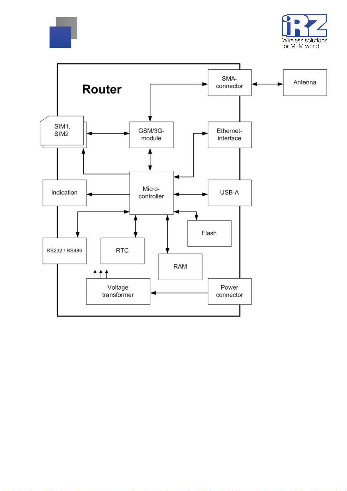
Fig. 2.1. Functional diagram of RUH2b rout er
10
Page 11

3. Appeara nce and interfa ces
3.1. Appearance
3.1.1. Connectors and external elements
The router is designed in an industrial version in a firm and lightweight plastic body.
Fig. 3.1. View from the SIM card side
Figure 3.1 numbers i ndicate:
1. SIM card #2 tray;
2. SIM card #1 tray eject button;
3. SIM card #1 tray;
4. SIM card #2 tray eject button;
5. Interface DB-9 connector (RS232 and RS485);
6. Reset settings button;
11
Page 12

Fig. 3.2. View from the antenna connect or side
Figure 3.2 numbers i ndicate:
7. Ethernet network connector;
8. USB Host connector;
9. SMA antenna connector, GSM antenna connections;
10. 6P6C power supply connector.
Fig. 3.3. View from the top (router indicators)
12
Page 13

3.1.2. Routers indicators
Router indi cators are l ocat ed on top of t he body (see fig. 3. 3). Pl ease see the Tabl e 3.1 f or t he expl anati on
of LED indicators signals and colours. The first column shows the name and a brief description of each
indicator purpose.
Table 3.1: Router indicators explanation
RUH2b router external indicators
Color
Description
POWER
power
ETHERNET
Ethernet port activity
CONNECT
GSM-module mode
SIGNAL
inpu t signal level
BUSY
busy of downloading *
SIM 1
SIM card #1 activity
Green Yellow Red No light
power is
connected
network cab le is
connected
3G
(HSPA/UMTS)
CSQ 20...31 CSQ 10...19 CSQ 0...9 GSM module is off
software download
or upgrade
SIM1 sel ected --- --- SIM1 is not used
--- --- no power
--- data transfer
2G
(EDGE)
--- ---
2G
(GPRS)
network cab le is
disconnected
no connection is
established
device is operating
or turned off
SIM 2
SIM2 sel ected --- --- SIM2 is not used
SIM card #2 activity
* – downloading is a process of preparing the router's operating system and software for work.
The maxi mum downlo ad t ime should not exceed 2-3 minutes .
13
Page 14

3.1.3. Decoding device label
Fig. 3.4. Product label
14
Page 15

3.2. Interfaces
3.2.1. Power supply
The power supply of the iRZ RUH2b router m ust be from a stabilised po wer supply with a voltage out put i n
the range 8-30 Volt s and the maximum current not less than:
800 m A at the voltage + 12V;
400 mA when the voltage is +24V.
A standard connect or 6P6C (RJ-25) i s used as a power co nnector. Please see t able 3.2 for connect ors
description.
Fig. 3.5. Power supply connector
Table 3.2: Purpose of connectors
Contact Signal Purpose
1
2 not used -
3 not used 4 not used 5 not used 6 GND System body (negative pole “-“)
+ U sup.
The positive pole of the DC power supply. It is protected by fused circuit and
overvoltage protection (when applied to the input voltage of over 30V) and
reverse polarity
15
Page 16

3.2.2. Serial port (COM-port, DB-9 connector)
A serial port defines the router f unctionality and allows solving t elemetry and telem echanics challenges. I t
can be used for:
Col lecting data or controlling the equipment on the network with additional software;
Connect ing two remote devices with COM interfaces via the Internet.
There are two serial ports available in RUH2b router, they are RS232 and RS485 interfaces. DB-9
connector (Fig. 3.6) is used to connect COM ports; please see Tabl e 3.3. for the connector purpose.
Note: A connection with external devices via RS422 interface can be obtained using the external RS422,
CAN converters
ATTENTION! Connecting the device to the rout er serial port is allowed only when bot h devices are turned
off.
Fig. 3.6. Interface connector
Table 3.3: Purpose of interface connect ors pins
Pin Signal Direction Purpose
1 not used - 2 RS232 - RXD Device → R outer Data reception
3 RS232 - TXD Router → Device Data transfer
4 RS485 - B Router ↔ Device Line B
5 GND general System body
6 not used - 7 not used - 8 RS232 - Power Router → Device External interface power supp ly
9 RS485 - A Router ↔ Device Line A
16
Page 17

3.2.3. Ethernet interface
The Ethernet interface is designed u sing a standard connec tor 8P8C (“RJ-45”). Please see table 3. 4. for
the description of the connector pins.
Fig. 3.7. Ethernet connector
Table 3.4: Purpose of Ethernet connectors pi ns
Pin Signal Direction Purpose
1 ETX P
2 ETX N
3 ERX P
4 not used - 5 not used - 6 ERX N
7 not used - 8 not used - -
Router ® PC
Router ® PC
PC ® Router
PC ® Router
Transfer, positive pole
Transfer, negative pole
Recepti on, positive pole
Recepti on, neg ativ e pole
17
Page 18

3.2.4. USB interface
The USB interface is designed using a standard USB-A "f emale" connector, and it works in accordanc e with
the USB 1.1 specification standard. Please see Table 3.5. for the descriptions of the connec tor pins.
Fig. 3.8. USB connector
Table 3.5: Purpose of USB connector pins
Pin Signal Purpose
1 VBUS
2 D- Differential data signal
3 D+ Differential data signal
4 GND
Power sup ply to p eripheral devices
Power sup ply to p eripheral devices
+5 Volts
"Body" circuit
3.2.5. SMA antenna connector, GSM/3G-antenna
The router is equipped wi th SMA type antenna connector.
When selecti ng an antenna, f irst please pay attent ion to t he positions f or operating on UMT S network, as
RUH2b router is desi gned prim arily to operat e on UMTS networks. O ther antenna m odels can also prov ide a
normal operation in cellular networks, but will not provide a full use of the router functionality, and
communication channels speed will be limited.
The process of connect i ng the ant enna t o the device is one of the key poi nt s f or the qual ity of a com put ing
complex buil t on the basi s of GSM-r outers. Before connecting an ant enna, it i s recommended t o install/check
the following settings:
Antenna cable connector quality;
Cable length and antenna sensitivity;
Antenna purpose (i.e. a miniGSM antenna is not always suited for tasks that require a broad
bandwidth).
18
Page 19

Fig. 3.9. SMA connector and antennas
To simplif y the process of determining the qual ity of connecti on, please see the tabl e 3.6 f or approximate
level of GSM/3G signal.
Note: It is not recommended to use a very long antenna cable. When using RG-58U cable, please take i nto
account the signal at tenuation rate, using the calculation of
Table 3.6: Signal level gradation
Signal le vel
dBm CSQ
-113 … -83 0 … 15 low (connection not guaranteed)
-81 … -67 16 … 22 medium
-65 … -51 23 … 31 good (steady reception)
~1 dB per meter.
Determination of GSM signal quality
Reminder: If the signal level is low, or there are connection problems, please refer t o the document
“Diagnostics and Troubleshooting of iRZ Routers”
19
Page 20

4. Pr eparing for operatio n
4.1. Connecting a SIM card
To ensure the connectivity of the router to the Internet through a cellular network you will require a SIM card
of a mini-SIM format. Prepare the SIM card (mini-SIM), reset your PIN code if necessary.
Please note: SIM card of a mini-SIM f ormat is different from other cards in size. P lease make sure you
receive a correct card from your provider, as the router is not designed to work with SIM cards of other
formats.
Please perform the following steps to ensure the router connectivity to the internet via a cellular network:
1. Remove the tray from the device
2. Fully extract the tray by pulling it towards you;
3. Place the SIM card
in the tray;
, by pushing the appropriate button;
20
Page 21

4. Insert the tray with your SIM card
in the slot for SIM #1 (slot on the router end).
If you require a redundant connec tion to t he Internet , please repeat al l the steps wit h the second S IM card
and place it in the tray slot for SIM #2.
Note: If the shutdo wn of the PIN verifi cation on the SIM car d is undesirable, pl ease refer to the I nternet
Connection Settings section of the document “Control and Moni toring of iRZ Routers”
Note: If the PIN-c ode test of the SIM card was not turned off , you can always do it t hrough the router web-
interface. Please see "Disable PIN" section of the “Control and Monitoring of iRZ Routers”
ATTENTION! Please remember that the tray placed in SIM card slot #1 must be turned so that the contact
part of the SIM card is facing down. T he opposite is true for the second SIM card: when i nstalling, t his SIM
card should hav e the cont act part up. Failure t o follow these instruc tions m ay resul t in a corr upted SIM card
and tray
21
Page 22

4.2. Device access
The device ac cess can be remote (v ia t he Internet, after the router i s connected on G PRS/EDGE/ 3G) and
locally (use an Et hernet cable), connecting the router directly to a computer.
Fig. 4.1. Device operation diagram
22
Page 23

4.2.1. Web interface access
To obtain acc ess to the router web-interface, please use any standard Internet browser that supports HTTP
1.0 , for example, Opera, Firefox, IE, Chrome.
Open the browser and perform the following steps:
1.
Enter the router IP address into the browser address line
;
Note: The IP address to access the router settings used by default is listed on t he sticker on the bottom side
of the router body.
If router is switched on, you will see a welcome page.
The welcome page cont ai ns a bri ef i nform ation about t he dev i ce stat us and t he net work: The dev i ce nam e
(unit name), the uptime since the device connect ion, the provider name, GSM connecti on type, GSM signal
level, the IP address, the connection speed, the number of transmitted and received data, etc.
2.
Enter your login and password
;
If your login and the password are correct, the access to the device main control interface opens.
Note: If you have forgotten the password to change the settings, you can reset the router to the default
factory settings with a standard login and password (see section 4.2.3 "Return to the facto ry settings" of
this guide).
23
Page 24

4.2.2. Internet connection via 3G/GSM channel
To connect the router to the Internet you will require:
3G ant enna, SMA antenna cable connec tor;
SI M card wit h a the Internet access servi ce package, and settings documentation;
SIM card tray (supplied with t he router).
Note: If you plan to connect the router to the Internet through an Ethernet connector, it may require a cable
(preferably CAT 5e) for connecting to the device with the provider's equipment
Recommendation: In order to avoid an unexpected loss of connec tion with the router because of a zero
balance, it is recommended to have a corporate agreement with your cellular service provider allowing post payment
For the router to connect to the Internet, please f ollow these steps:
1. Place the SIM card in a SIM card tray;
2. Place the SIM card into the slot (at the end of the router);
3. Connect the antenna;
4. Turn the unit power on;
5. Wait for 2 to 5 minutes.
The router m ust connect t o the Internet . To obtai n the Internet acc ess, please connect the com puter with
the router via the Ethernet interface (IP address will be issued automatically as per DHCP).
4.3. Return to the factory settings
Please follow these steps to return to the factory settings:
1. Turn off the power (the router must be off);
2. Connect the power, turn t he router on;
3. Press and hold "RST" button (i ndicated by digit "6" on Figure 3.1);
4. In 25 seconds, "BUSY" LED must blink 3 times;
5. This means that the settings have been changed and you can release "RST" button.
After this, t he rout er wil l be reset t o the factory setti ngs. Pl ease note t hat i n thi s case t he rout er I P addre ss
is 192.168.1.1
24
Page 25

4.4. Device installation
RUH2b router has special slots on the bottom of it s body to enable mounting i t on a DIN-rail without any
additional tools:
1.
Take your router and simply clip its bottom part to a DIN-rail
When mounting on a wall, the bottom of the router has special openings for mounting. The distance
between the openings is 90 mm. Both the horizontal and the vertical mounting are possible.
;
Fig. 4.2. Installation plan
25
Page 26

RUH2b has HardFix-mount, to securely hold the device for DIN-rail.
Installinf on DIN-rail Removing from DIN-rail
1. Hook the router overhead fasteners for one
edge of the DIN-rail;
2. Pull the router to compress the upper fasteners;
3. Snap on DIN-rail mounting bottom element;
1. Pull the router towards the antenna connector to
compress the upper fasteners;
2. At time of the upper compression elements,
unsnap from the DIN-rail bottom of the router;
3. Then simply remove the router;
26
Page 27

When installi ng the router on a wall , you can use a speci al pad, please see abov e. You can pri nt out this
figure, cut it out, and easily determine the distance for the openings without any additional measurements.
Attention: Printers can distort the dimensions when printing. Aft er printing page, please make sure that t he
information provided in scale on the figure (the size is specified in centimeters) is the same as the actual size.
27
Page 28

4.5. Software functionality
Table 4.1: Router functionality description
Name Brief description Explanation and operating principle
Key functions
OpenVPN
2 SIM
Serial Port
Deployment and network protection
IPSec
Firewall
GRE
Secure network tool OpenVPN is one of the core services, defining iRZ
Reserving the SIM card Protects against the loss of communication with the
Processing COM port data Provides and monitors operation with data going
Transmitted data security A high-reliability data protection tool often used in the
Built-in network screen The network screen is one of the main components of
Point-to-point data tunnelling. Virtual channel connection tool between two IP network
router functionality. OpenVPN service has many facets,
and its setting depends on a specific application. Key
features are:
Secure data channel possibility;
Combining multiple geographically separated points
in a single virtual space (a virtual IP-network);
Cost reduction for external IP addresses by
changing the role of nodes at the connection time
(client - server)
object by automatically transitioning to the second SIM
card
through the COM port. Defines the primary router
functionality using the possibility of a transparent
communication channel between the connected device
and a remote object (dispatch, or other device)
banking communications. It allows creating a point-topoint connection between two nodes, while
consolidating subnets dispersed in space.
any network border device. It provides protection
against the penetration into the internal network space
that the router is connected to. It can also perform
tasks, s uch as ports redirection (port forwarding)
nodes. It can be used to connect networks.
DHCP
Port Forwarding
Static Routes
The s ervi ce of pr ovidi ng IP ad dresses. It provides and monitors the network address space
that the router is connected to.
TCP/UDP ports forwarding It allows communicating with devices located in the
inner IP network to which the router is connected by
forwarding traffic from the external interface to the
initially designated internal node.
Static routing It stores user specified routes to a subnet, or a node.
28
Page 29

Table 4.1: Router functionality description (continuation)
Name Brief description Explanation and operating principle
Redundancy and fault-tolerance
Watchdog
Reserve Link
USB-LAN
Alias
Daily Reboot
Backup/Restore
VRRP
Management, maintenance and diagnostics
Web-interface
Telnet
Watchdo g timer It constantly monitors the state of the operating system
Reservi ng an Internet channel Allows using a GSM connection as a reserve channel
Additional Ethernet interface via USB It provides the possibility to use a USB interface as a
A virtual IP address on the main Ethernet It allows using a seco nd IP address on a single
Daily reset It can be used for a daily reboot of the router. It is used
Save / restore the configuration It ensures the safety of all the device settings, and
Reserving the main network gatew ay VRRP protocol is designed to provide a possibility to
Remote access to web interface
Remote access to the console It provides the user with the ability to control the router
for deadlocks. The function is relevant in solutions with
an increased requirement for fault-tolerance .
when there is no wired Internet connection.
network (Ethernet) interface. It may be included in the
operation with the Reserve li nk function.
physical Ethernet interface.
as a preventive measure for the device deadlock.
allows recovering them on this or other devices.
maintain a network performance through the use of
multiple replaceable routers in the event of a failure of
one of them.
The main tool for the router management, setting and
status monitoring
using Linux commands. The use of the management
console greatly expands the router control possibilities.
SSH
SNMP
Send Report
Ping Test
System Log
Connection Log
Note: You can see the list of a vailable commands in
the document “Control an d Monitoring of iRZ Routers”
Secu re remote access to the console Equivalent to Telnet, all the data input and output is
performed thr ough a s ecure channel
Monitor the status in the network A dedicated protocol for the control and monitoring of
the network devices. In the current version, it only
allows monitoring the interfaces status, and receiving
more information about the device
Generating all the debug information Page to send the debug information. Please use It
when contacting iRZ support team to reduce the time
required to identify the issue
Check the connection wi th the node A standard command to check the connection to the
node at the IP level, may be made via a web interface
Sys tem even ts r egistration service System log page allows monitoring all system events.
Several modes of registering messages are accessible.
Internet connections registration service Internet connection log It allows to obtain information
on the past connections and connection err ors.
29
Page 30

Table 4.1: Router functionality description (continuation)
Name Brief description Explanation and operating principle
Functional expansion
Startup Script
IP-Up Script
IP-Down Script
Additional functions
Send SMS
Disable PIN
NTP / Clock
Unit Name
Autorun Script It allows to significantly increase the in-built
functionality of the router. Commands/script saved on
this page will be performed every time t he device
starts.
Autorun Script It is equivalent to Stаrtup-Sсript , but run
script/command occurs after a successful GPRS
connection
Autorun Script It is performed when the GPRS connection is off
Send user SMS messages It allows sending a short message to a specified
number. Only Latin letter s are s upported
Disable PIN verification on SIM card It disables protection of PIN-code access on a SIM card
Clock setting and synchronization It allows specifying the exact time, and set up an
integrated NTP "server time". It supports
synchronization with ext ernal root NTP ser vers
Device unique name A string specified on this page is used to make the
router recognizable within the project
30
Page 31

5. Con tact s and Suppor t
New document versions and software are available using:
St. Petersburg
The company’s website: www.radiofid.ru
Phone number in St. Petersburg: +7 (812) 318 18 19
E-mail: support@radiofid.ru
Moscow
The company’s website: www.digitalangel.ru
Phone number in Moscow: +7 (495) 974 74 22
E-mail: info@digitalangel.ru
Our support team i s ready to assist you with any quest ions you might have when installing, configuring or
solving issues with our equi pm ent.
In the event of an issue, when contacting our technical support, please indicate t he router soft ware version.
We also recomm end that you attach to your email the logs of issues you hav e experienced wit h the service,
screen shots, and any other useful inf ormati on. The more i nf ormati on you can pr ovi de t o t he support t eam, the
faster they can resolve the issue.
Note: Before contacting the technical support, it is strongly recommended that you update the router
software.
Attention! The violation of conditions of use (m isuse of the router) voids the devi ce warranty.
31
 Loading...