

iRZ iON FM User Manual

USER GUIDE
Navigation User Terminal
iON FM

Table of Contents
1. INTRODUCTION ................................................................................................................... 5
1.1. Warnings and Recommendations ........................................................................................... 5
1.2. Technical Specifications ...................................................................................................... 6
1.3. Package Contents ............................................................................................................... 7
1.4. Device Overview ................................................................................................................ 8
1.4.1. Device Overview and Purpose ...................................................................................... 8
1.4.2. Navigation Terminal Functions .................................................................................... 8
1.4.3. The Tracking System Operation Diagram ........................................................................ 9
1.4.4. Navigation Terminal Connectors .................................................................................10
1.4.5. Navigation Terminal System ......................................................................................11
1.4.6. Terminal Inputs/Outputs ..........................................................................................11
1.4.7. Terminal Operation Modes .........................................................................................14
1.5. Dimensional Drawing .........................................................................................................21
2. DEVICE PREPARATION PROCEDURES ......................................................................................22
2.1. Interface Cable .................................................................................................................23
2.2. Indication .......................................................................................................................24
2.3. Replacing SIM Card and Connection to a PC ...........................................................................25
3. DEVICE CONNECTION ...........................................................................................................27
3.1. Connecting Power without Battery Cutoff Switch ....................................................................28
3.2. Connecting Power with a Battery Cutoff Switch ......................................................................28
3.3. Ignition Circuit Connection ................................................................................................29
3.4. RS485 LLS Connection .......................................................................................................29
3.5. Tachometer Connection ...................................................................................................... 30
22

3.6. Alarm Button and Any Contact Sensor Connection .................................................................. 30
3.7. Connecting the LLS with an Analog Output ............................................................................ 31
3.8. Current Output Analogue Sensor Connection ..........................................................................31
3.9. Connecting Analog/Pulse Sensor with an Open-Collector Output ...............................................32
4. CONFIGURING the DEVICE USING the CONFIGURATOR UTILITY ..................................................33
4.1. Driver Installation ............................................................................................................. 33
4.1.1. Installing Drivers on Windows XP ................................................................................33
4.1.2. Installing Drivers on Windows 7 ..................................................................................37
4.1.3. Installing Drivers on Windows 8 ..................................................................................41
4.2. Overview .........................................................................................................................48
4.3. Terminal Configuration ......................................................................................................50
4.3.1. “Server” Tab...........................................................................................................51
4.3.2. “SIM Configuration” Tab ...........................................................................................52
4.3.3. “Track Points” Tab ..................................................................................................53
4.3.4. “Inputs” Tab ..........................................................................................................54
4.3.5. “Outputs” Tab ........................................................................................................56
4.3.6. “RS-485” Tab .........................................................................................................57
4.3.7. “Powersaving” Tab ..................................................................................................61
4.3.8. “Data Grouping“ Tab ................................................................................................62
4.4. Service Configuration of the Terminal ...................................................................................63
4.4.1. Firmware Update .....................................................................................................63
4.4.2. Password Change.....................................................................................................64
4.4.3. Service Commands ...................................................................................................64
4.4.4. Working with the Configuration File ............................................................................64
4.5. CAN-LOG iRZ Online Diagnostic ............................................................................................65
33

TERMS AND ABBREVATIONS ......................................................................................................67
4

1. Introduction
This document contains information on preparation procedures of the iON FM navigation user terminal for
operation.
Version Date Prepared by Revisions
1.0 14.03.2016 V. Golovin Main document
1.0.2 07.04.2016 V. Golovin Revisions: minor changes in sections 1.4.6, 1.4.7, 2.2, 2.3, 4.3.4, 4.4.1
1.1 15.07.2016 V. Golovin Added: Section 4.3.5 “Aggregation” Tab
Changes: Section 4.31.1 – adjustments of data (configuration app.)
1.1.1 30.08.2016 V. Golovin Revisions: maximal voltage (1.4.6)
1.2 06.12.2016 V. Golovin Revisions: configurator updates (4.3, 4.3.1–4.3.8, 4.4, 4.4.1–4.4.4, 4.5)
1.2.1 07.12.2016 V. Golovin Revisions: corrections in chapter 4.4
1.2.2 23.01.2017 V. Golovin Revisions: corrections in chapter 1.2
1.2.3 09.06.2017 V. Golovin Revisions: figure in chapter 1.4.3
1.2.4 27.07.2017 V. Golovin Revisions: adjustment of working with CAN-LOG (4.5)
1.2.5 17.08.2017 V. Golovin Revisions: parameters of frequency input (1.4.6)
1.2.6 08.11.2017 V. Golovin Revisions: added parameters I/O (1.4.6)
1.1. Warnings and Recommendations
Before starting to use the device, please read the safety rules described in this section.
CAUTION! The device uses the cellular technology and can cause radio interference to medical and other
equipment. Thus, if you are in the area where use of cellular devices is not allowed, disable the controller.
CAUTION! The controller can cause interference to cardiac pacemaker or hearing aids. Switch off the device
in medical centres.
CAUTION! Switch off the device if you are in the area of blasting operations. The controller can cause inter-
ference when the operations are underway. Thus, follow the instructions and directions in such areas.
5

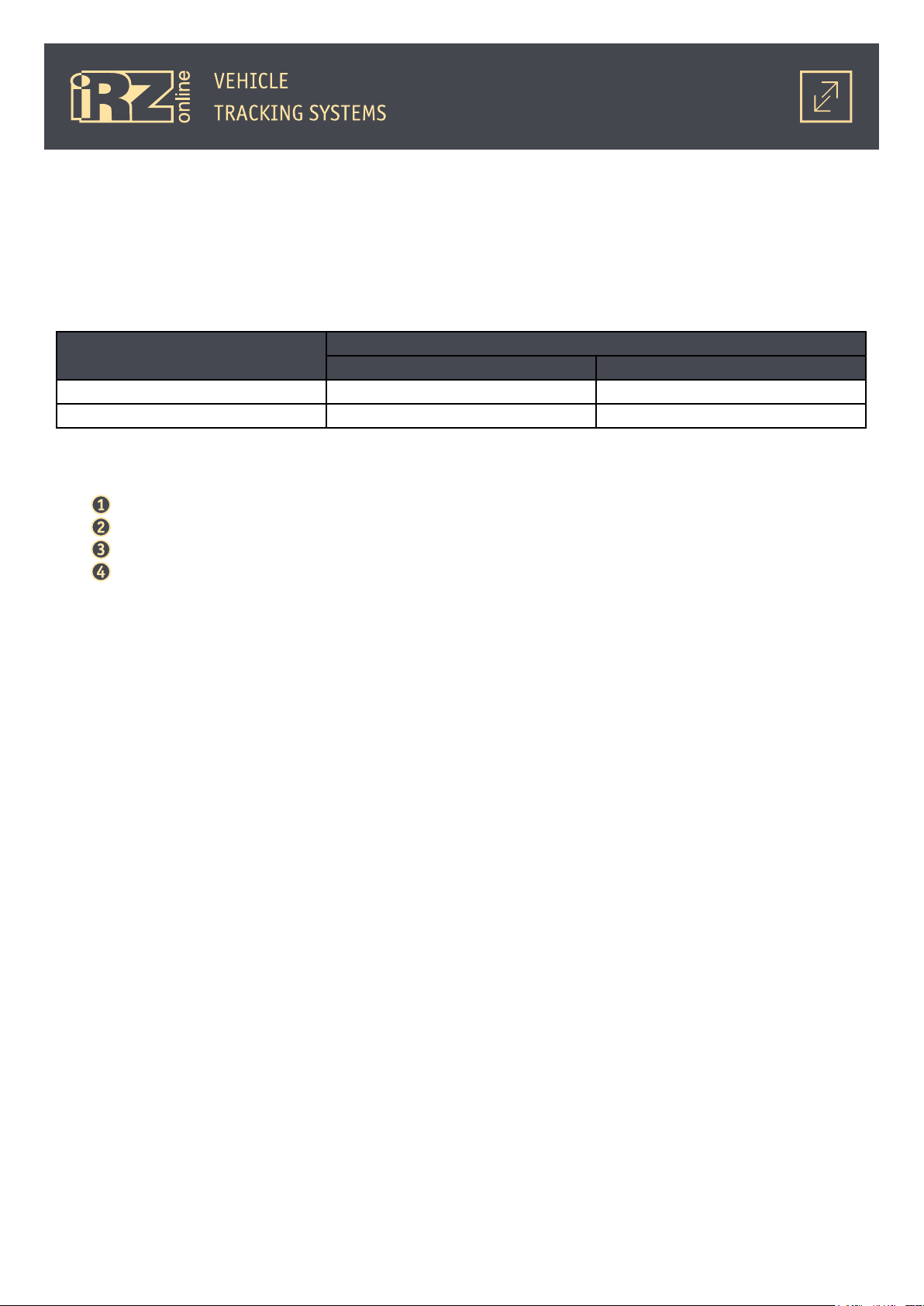
1.2. Technical Specifications*
General Features
Navigation receiver GPS/GLONASS
Frequency bands GSM/GPRS 900/1800 MHz
Antennas External GPS/GLONASS antenna
External GSM antenna
Flash-memory 16 MB
SIM card holder Inside the case
Built-in accelerometer Three-axis
Electrical Specifications
Supply voltage from 8 to 48 V
Current consumption in various modes
(at 12V power voltage), not exceeding
Built-in battery Li-Pol, 550 mAh
Microfit 10 connector Device power
FAKRA SMB connector Connection of an external GPS/GLONASS antenna
FAKRA SMB connector Connection of an external GSM antenna
SIM card Mini SIM - standard SIM card (or SIM-chip**)
Micro USB connector (inside the housing)
Dimensions
Net weight net, not exceeding 90 g
Gross weight, not exceeding 120 g
Operating temperature
* technical specifications are subject to change by the manufacturer without prior notice
** optional
*** total number of inputs/outputs amounts to 6
● 100 mA (operating mode, the battery is charged)
● 250 mA (operating mode, the battery is discharged)
● up to 10 mA (sleep mode)
Connectors and Interfaces
RS485 interface
4 multipurpose inputs (analog, discrete [logic], frequency, pulse)***
2 outputs (open collector)***
Connection to a PC for configuration
Physical Specifications
94
× 74 × 20 mm
from -30
ºС to +80ºС
6

1.3. Package Contents
The delivery package of the iON FM navigation user terminal contains the following components*:
Indication Name Quantity
iON FM 1 pcs
GSM antenna 1 pcs
GPS/GLONASS antenna 1 pcs
10-pin interface cable 1 pcs
* the package collection and content are subject to change by the manufacturer without prior notice
7

1.4. Device Overview
1.4.1. Device Overview and Purpose
iON FM is a navigation user terminal (NUT) designed for installation on the object of observance, collection, storage and transmission of data to the server for further processing. The navigation terminal receives
location and time data from the GPS/GLONASS satellites. The collected data is transmitted to the server over
the GSM network using the GPRS packet-switched service. The data on the server is available to a user through
the dispatching software.
It is necessary to remember that iON FM is just a part of the tracking system. m. The navigation terminal
itself is responsible for data acquisition and transmission from the surveillance object to the server where the
data is processed and provided to an end user.
Overall, the tracking system enables you to complete a wide range of tasks:
● safety issues — vehicle travel data, operating disturbances, etc.;
● efficiency improvement — control of a vehicle use only in authorized operations, efficiency analysis
of the performed tasks;
● ensuring operation transparency — all data on vehicle travels, fuel consumption and other data is
transmitted to the server and available online;
● statistical data collection — in the process of vehicle operation an end user is provided with various
data which can simplify and even improve efficiency of performing tasks. Moreover, this data helps to make
calculations of different economy-related measurements.
1.4.2. Navigation Terminal Functions
The iON FM navigation terminal as a part of the tracking system fulfils the following functions:
● fixes the vehicle location (space coordinates) using GPS/GLONASS module;
● determines overload, direction change, turns using the built-in accelerometer;
● collects data from the sensors:
• digital sensors;
• analog sensors.
8
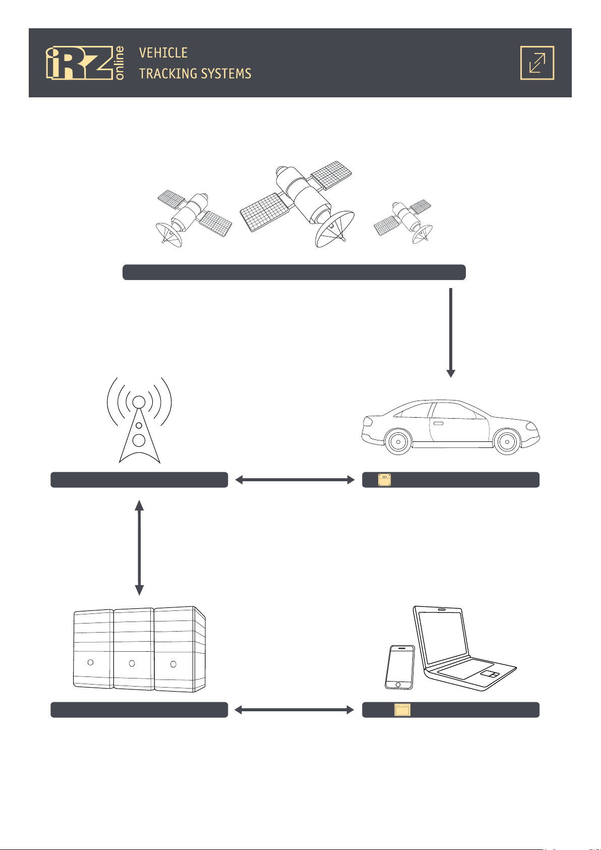
1.4.3. The Tracking System Operation Diagram
GPS/GLONASS Satellites
location data
Monitored object (vehicle)
GSM Base Station Navigation Terminal
GSM/GPRS
user commands, location data,
sensors data, etc.
Internet
Tracking System Servers Web browser
user commands
User devices
Internet
location data,
sensors data, etc.
Fig. 1.1. The Tracking System Operation Diagram
9
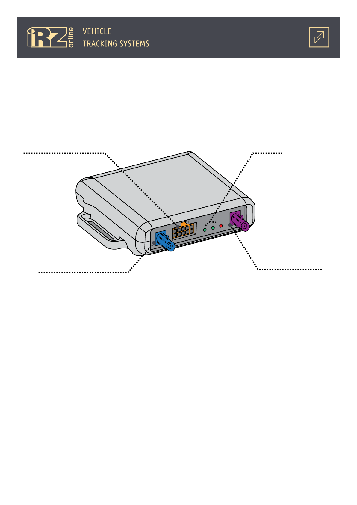
1.4.4. Navigation Terminal Connectors
iON FM is a compact device encased in a plastic housing which supports connection to external power, as
well as to various external devices and sensors.
Interface connector is situated outside of the casing, while SIM card access, Micro USB connector and a
battery are fitted inside.
Navigation terminal connectors are shown in the figure:
Microfit 10 Connector LEDs
FAKRA connector
GPS/GLONASS antennas
Fig. 1.2. iON FM navigation terminal connectors
FAKRA connector
GSM antenna
10
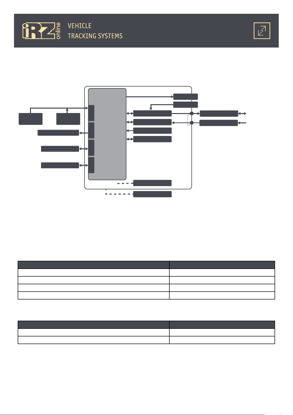
1.4.5. Navigation Terminal System
Navigation terminal structure diagram:
iON FM
Analog LLS 1
...
Analog LLS 4
Actuating mechanism
Digital sensors
PC
Processing unit
INPUTOUTPUTRS485
USB
GSM module
GPS/GLONASS module
Accelerometer
Flash memory
Battery
Power supply
Indicators
SIM card
GSM antenna
GPS/GLONASS antenna
FAKRA SMB
Fig. 1.3. iON FM navigation terminal structure diagram
GSM/GPRS
Satellites
GPS/GLONASS
1.4.6. Navigation Terminal Inputs/Outputs
Inputs:
Parameter Value
ADC measurement range: 0 to 30 V
Trigger thresholds of discrete inputs adjustable value*
Input resistance of inputs ~150 kΩ
Inputs pull-up voltage 4 V
* Levels of logical 1 and 0 can be adjusted. Minimal value is 0V, maximal — 30V
Outputs:
Parameter Value
Maximal output load current 500 mA
Outputs polarity coupled to negative
Inputs.
Inputs IN1-IN4 of Microfit 10 connector are multipurpose and are intended for reading external devices,
connected to iON FM terminal. All the read data may be transmitted to web-monitoring server for the following
processing.
11

Operating mode can be set for each of the physical inputs (IN1 - IN4). There are 4 types of inputs:
● frequency;
● pulse;
● analog;
● logic.
Correct operation of all iput types, excep analog, require the following parametetrs to be configured:
● set levels for logic 0 and logic 1;
● enable/disable pull-up resistors.
Configure input type, logic 1 and 0 levels via
NOTE! To decrease GPRS traffic, iON FM is fitted with input readings filter: if the reading has not changed,
the device does not transmit it to server. This allows for significantly economise GPRS traffic and funds at
the user’s SIM card.
Frequency input type.
Frequency input type is intended for measuring the frequency of periodic signal, received by input, and
its subsequent transmitting to a server. The measured may also be read using control commands.
Electrical parameters of frequency input:
● form of the input signal may be of the following types: sine, rectangle, square;
● periodic signal frequency range: 0 (Hz) to 4 (kHz);
● maximum permissible voltage of input signal: 30 (V);
● recommended minimal voltage of the impulse signal: 0.5 (V);
● input pulse is determined by rising edge;
● maximal error of frequency measurement: 10%.
Conf_iRZ.exe program, in Multipurpose inputs tab.
NOTE! Connecting input to the frequency generator with open collector requires enabling pull-up connec-
tion to this input.
Pulse input type.
Pulse input type is intended for injecting a singular pulse or a periodic pulse. The amount of such pulses
will be counted and summarized for consecutive transmission of the resulting value to web-monitoring server.
The resulting value may be read using the corresponding control commands. Functionally, pulse input type is
a pulse counter.
Electrical parameters of the pulse input:
● pulse signal frequency range: 0 (Hz) to 4 (kHz);
● form of the input signal may be of the following types: sine, rectangle, square;
● maximum permissible voltage of input signal: 30 (V);
● recommended minimal voltage of the impulse signal: 0.5 (V);
● input pulse is determined by rising edge;
12

● maximal value of pulse counter: 65535. (after reaching that value, the calculation starts over);
● maximum counter error: 1%.
NOTE! Connecting input to the frequency generator with open connector requires enabling pull-up connec-
tion to this input. Zero the counter out only when it is necessary to reset previously accumulated values.
Analog input type.
iON FM terminal supports feeding analog signal of steady voltage that will be measured and averaged out
for further transmission to a server.
Electrical parameters of analog input:
● maximum permissible voltage of input signal: 30 (V);
● recommended minimal voltage of the impulse signal: 0.5 (V);
● input signal level measurement is only taken when the voltage is positive in relation to negative
power supply; negative voltage is ignored;
● maximum voltage error: 1% (300 mV).
NOTE! Disconnect pull-up resistors when configuring input to function as analog.
Logic input type.
Logic input type is used for feeding signal with steady voltage level. The voltage will be measured and interpreted as logic 1 or logic 0 for further transmission of the interpreted logic value to web-monitoring server.
The measured may be read using corresponding control commands.
Electrical parameters of logic input:
● minimal level of logic 0: 500 (mV);
● maximal level of logic 1: 30000 (mV);
● cosntant component of voltage on input with enabled pull-up resistors: ≈ 4 (V);
● input signal’s logical level is only determined only at positive voltage, negative is ignored;
● negative is ignored;
● maximum voltage error: 1% (300 mV).
Control outputs.
Control outputs OUT5 and OUT 6 are intended for controlling external devices connected via Microfit 10
connector. Output status is configured using the corresponding commands. These two outputs are fitted with
open collector (OC) and commute (close) any connected external devices (e.g. a relay) to negative of power
supply (return wire, mass).
Electrical parameters of OUT5 and OUT 6 outputs:
● maximal value of commutation current (load current): 0.5 (A);
● maximal voltage on collector at each output: 30 (V);
● there is no need to connect a fuse diode when commutating inductive load; there is a built-in one.
13

Default settings of multipurpose inputs/outputs.
Inputs/Outputs Default setting
IN1, IN2 analog
IN3, IN4 logic (logic 1 = 2.8 V, logic 0 - 2.2 V)
OUT5, OUT6 disabled
1.4.7. Terminal operating modes
iON FM terminal supports 5 operating modes, each assigned for different tasks as well as regulated within
certain range of power consumption for power-saving modes. Power saving is achieved by disabling certain
functional modules for prolonged intervals of time.
List of iON FM terminal operating modes:
● “Main mode” — fully functional operating mode with maximal power consumption;
● “Power-saving mode” — power-saving mode, may also be designated as “Mode 1”;
● “Sleep mode” — power-saving mode, may also be designated as “Mode 2”;
● “Deep sleep mode” — power-saving mode, may also be designated as “Mode 3”;
● “Active mode” — fully functional operating mode with maximal power consumption.
14
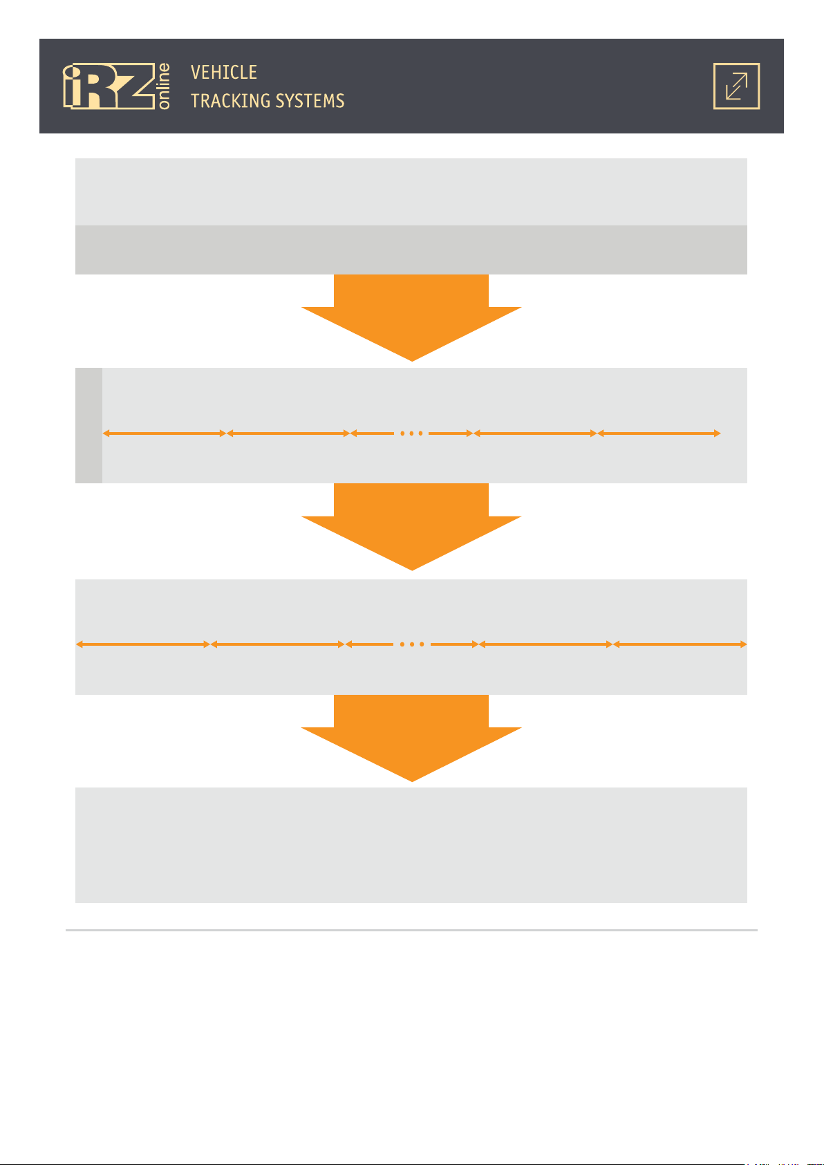
Main mode
Vehicle movement is registered. Terminal is powered from onboard network or built-in battery.
Vehicle movement halt
1 hour*
Vehicle movement is not registered. Terminal is powered from onboard network or built-in battery.
12 hours **
The terminal goes online for transmitting accumulated data and current GPS coordinates at set periods of time
Vehicle movement is not registered. Terminal is powered from onboard network or built-in battery.
12 hours ****
The terminal goes online to transmit current LBS coordinates at set periods of time (once per 24 hours by default).
Vehicle movement was not detected for a set amount of time (1 hour by default).
Switch
to Mode 1
Mode 1 (power-saving mode)
1 hour*** 1 hour***
(once per 60 minutes by default).
Switch
to Mode 2
Mode 2 (Sleep mode)
24 hours**** 24 hours**** 24 hours****
Notes:
Battery charge is depleted
to critical level
Switch to Mode 3
Mode 3 (deep sleep mode)
The terminal is in maximum power-preservation mode. External power supply is absent.
* the time may be set using the configurator
or PW#TW1 command
** the time may be set using the configurator
or PW#TW2 command
Fig. 1.4. iON FM operating modes diagram
*** the time may be set using the configurator
or PW#TS1 command
**** the time may be set using the configurator
or PW#TS2 command
15
Main mode
In the “Main mode”, iON FM terminal performs all of its function in real time; all of its electronic peripherals are enabled to provide complete functionality. In this mode, the device determines GPS and LBS coordinates, reads multipurpose inputs and RS-485 bus, and transmits these readings to web-monitoring server via
GPRS channel.
“Main mode” current consumption:
Built-in battery status External power supply voltage
12 V 24 V
Charged Max. 90 mA Max. 50 mA
Discharged Max. 250 mA Max. 130 mA
“Main mode” is the only mode that is able to automatically switch to other operating modes for power
preservation. iON FM is configured to switch to other modes in the following order:
“Main mode”;
“Power-saving mode” (Mode 1);
“Sleep mode” (Mode 2);
“Deep sleep mode” (Mode 3).
List of “Main mode’s” continuously operating peripheral modules:
● multipurpose inputs/outputs - data reading and controlling of connected devices;
● motion sensor - accelerometer for determining acceleration during motions.
● RS485 data bus - for processing LLS or CAN-LOG data;
● internal memory (black box) - for recording of all accumulated data;
● GPS module - for determining precise GPS coordinates;
● GSM module - for transmitting all of the accumulated date to monitoring and LBS location server.
By default (factory settings), iON FM terminal works in “Main mode” after external power supply over 9 V
has been connected and OS has been launced. The terminal also switches to “Main mode” after waking from
power-saving modes:
“Mode 1”, “Mode 2” and “Mode 3” ( if the terminal has been previously set to work in “Main mode” 0.
“Main mode” is a default operating mode of iON FM, but may be switched to any other via PW#MODE control command.
iON FM terminal remains in “Main mode” while motion sensor detects motion. For example, when the terminal is installed in a vehicle. Once movement halts, movement timeout is initiated (configured via PW#TW1
and PW#TW2 commands or configurator program). After timeout expires, the terminal switches to a certain
power-saving mode, depending on how much time has passed: “Mode 1” or “Mode 2”.
For operation in “Main mode”, it is not important, which power source is used. Regardless of whether it
is external or built-in battery, the terminal will switch its power-saving modes in the order described above.
“Power-saving mode” (Mode 1)
While in “Power-saving mode”, iON FM keeps performing most of its functions in real time. However, only
some of its electronic peripherals are enabled continuously - others are only activated periodically. For example, determination of GPS and LBS coordinates and their transmission to web-monitoring server over GPRS
channel is not carried out continuously, but at periods of time, set using configurator or PW#TS1 control command. This interval is 60 minutes by default. While the connection is disabled, the terminal saves the data in
16

the internal memory (black box) for furhter transmission to monitoring server.
“Mode 1” current consumption:
Built-in battery status External power supply voltage
12 V 24 V
Charged Max. 40 mA Max. 20 mA
Discharged Max. 250 mA Max. 130 mA
List of periodically transmitted data in “Mode 1”:
● GPS coordinates
● accumulated LLS and CAN-LOG data
● accumulated data from multipurpose inputs.
List of data, periodically received from server, in “Mode 1”:
● user commands.
List of continuously active peripheral modules in “Mode 1”:
● multipurpose inputs/outputs — data reading and controlling of connected devices;
● motion sensor — accelerometer for determining acceleration during motions.
● RS485 data bus — for processing LLS data;
● internal memory (black box) — recording of all accumulated data;
● GPS module — for determining GPS coordinates.
List of periodically active peripheral modules in “Mode1”:
● GSM module — determining LBS coordinates and transmission of all accumulated data to monitoring
server.
iON FM terminal switches to “Power-saving mode” only if this mode is allowed by PW#EN1 command (al-
lowed by default), and the following conditions are consecutively met:
The terminal is at rest and motion sensor does not detect movement;
Motion timeout set by control command PW#TW1 (60 minutes by default) has expired.
When setting timeout for switching to “Mode 1” via PW#TW1 command, make sure its value is less than
that of PW#TW2 command (for “Mode 2”). Otherwise the value will not be accepted and user will receive an
error message. Keep in mind, that timeout counter starts for PW#TW1 and PW#TW2 simultaneously, in other
words, these intervals are not summarized.
The terminal remains in “Power-saving mode” until one of the following events occurs:
● motion sensor sends alerts upon movement detection (in this case the terminal switches to “Main
mode”);
● timeout for switching to next power-saving mode -”Sleep mode” (“Mode 2”) - expires. Set with
PW#TW2 command;
● built-in battery charge depletes to a critical level (with external power disabled). In this case the ter-
minal switches to “Deep Sleep Mode” (“Mode 3”), i.e. the terminal automatically switched from “Mode
1” to “Mode 3”, bypassing “Mode 2”. Switching do “Mode 2” can be forbidden with PW#EN2 command
(allowed by default).
17

To manually switch the terminal to “Mode 1”, send PW#MODE=2 command. Keep in mind, that if switched
to “Mode 1” manually, the device will keep operating in this mode only. It will not switch to other modes except for “Mode 3”, since the terminal always switches to “Mode 3” when the built-in battery charge is depleted
to a critical level.
If iON FM terminal has switched to “Mode 1” from “Main mode”, then power source is irrelevant — be it
built-in battery or external source - since the terminal will follow the same order of switching from one powersaving mode to another to preserve energy.
“Sleep mode” (Mode 2)
In “Sleep mode”, iON FM terminals ceases to perform most of its functions and all of its electronic peripherals, except for motion sensor, is disabled for energy conservation. At set periods of time (set by configurator
or PW#TS2 control command), the terminal wakes up for transmitting LBS coordinates via GPRS channel to
monitoring server. By default, the period is set to 1440 minutes (24 hours). When configuring this interval,
keep in mind, that timeout counter starts for PW#TW1 and PW#TW2 simultaneously, in other words, these intervals are not added up.
“Mode 2” current consumption:
Built-in battery status External power supply voltage
12 V 24 V
Charged Max. 9 mA Max. 5 mA
Discharged Max. 250 mA Max. 130 mA
List of periodically transmitted data in “Mode 2”:
● location LBS coordinates (no other data is transmitted).
List of data, periodically received from server, in “Mode 2”:
● user commands.
List of continuously active peripheral modules in “Mode 2”:
● motion sensor — accelerometer for detecting acceleration during movement and for “waking up”.
List of periodically active peripheral modules in “Mode2”:
● GMS module — for determining LBS coordinates to transmit them to monitoring server.
The terminal switches to “Sleep mode” only if it is allowed by PW#EN2 command (allowed by default) and
the following 2 conditions are met consecutively:
The terminal is at rest and motion sensor does not detect movement;
Motion timeout, set by control command PW#TW2 (720 minutes by default), has expired.
iON FM remains in “Sleep mode” until one of the following events occurs:
● motion sensor sends alerts upon movement detection (in this case the terminal switches to “Main
mode”, if this mode has not already been set as operational);
● built-in battery charge is depleted to a critical level (with external power disabled); the terminal
switches to “Deep Sleep Mode” (“Mode 3”).
To manually switch the terminal to “Mode 2”, send PW#MODE=3 command. Keep in mind, that if switched
18

to “Mode 2” manually, the device will keep operating in this mode only. It will not switch to other modes except for “Mode 3”, since the terminal always switches to “Mode 3” when the built-in battery charge is depleted
to a critical level.
Power supply of the terminal is particularly important: external power or built-in battery. In this mode,
the terminal will draw power supply from external source if such is available. This means that the terminal will
remain in “Mode 2” indefinitely, until external supply’s voltage decreases to 9 V. For example, when the vehicle’s ignition is switched off. After that, the terminal will switch to built-in battery until its charge is depleted
to a critical level, while remaining in “Mode 2”. After that, it will switch to “Deep Sleep Mode” (“Mode 3”).
NOTE! During prolonged parking, iON FM may completely discharge the vehicle’s AC battery. To avoid that,
connect the terminal to the part of the fuse box that is de-energized when ignition is switched off. Alternatively, use battery disconnect switch.
“Deep Sleep Mode” (Mode 3)
In “Deep Sleep Mode”, the terminal disables all of its peripheral modules for maximal energy conservation. In this mode the device may only be powered from built-in battery.
For automatic switch to “Mode 3”, two conditions must be met:
● external power supply must be disconnected or its voltage must be below 9 V;
● internal power voltage of built-in battery must drop to a critical level (set by manufacturer).
The terminal cannot be switched to “Mode 3” by PW#MODE command. The terminal will remain in this
mode until external supply is detected. The terminal periodically checks its presence.
After receiving power supply with voltage over 9 V, the terminal “wakes up” and switches to mode previously set to it by PW#MODE command; built-in battery will start charging up. No communication sessions are
carried out in “Mode 3”.
Active mode
In “Active mode”, iON FM terminal performs all of its functions in real time; all of its electronic peripherals
are enabled to provide complete functionality. In this mode, the device determines GPS and LBS coordinates,
reads multipurpose inputs and RS-485 bus, and transmits these readings to web-monitoring server via GPRS
channel.
“Active mode” is similar to “Main mode”, but has some significant differences. In this mode, the terminal
is fully functional for as long as internal or external power allows it. As opposed to “Main mode”, the terminal
cannot automatically switch to other power-saving modes (except for “Mode 3”).
Enable “Active mode” when continuous operation of the terminal is required or there is no need to conserve energy. With the exception of features listed above, list of peripheral modules, functions and energy
consumption of “Active mode” is identical to that of “Main mode”.
The only way to switch the terminal to “Active mode” is manually via PW#MODE=1 command.
If iON FM terminal was switched to “Mode 3” from “Active mode”, then, after external power supply over 9
V has been connected, the device will switch to “Active mode” and the built-in battery will start charging up.
Power source is very important for operating in “Active mode”. Please keep in mind, that if voltage of
external power is over 9 V (for example, vehicle’s AC battery), then the terminal will be powered from that
external source as opposed to its built-in battery. This way, the terminal will remain in “Active mode” indefi-
19

nitely, until external power voltage drops below 9 V. After that, the device will switch to built-in battery, while
remaining in “Active mode”, until its charge is depleted to a critical level. In this case, the device will automatically switch to “Deep Sleep Mode” (“Mode 3”).
NOTE! During prolonged parking, iON FM may completely discharge the vehicle’s AC battery. To avoid that,
connect the terminal to the part of the fuse box that is de-energized when ignition is switched off. Alternatively, use battery disconnect switch.
20
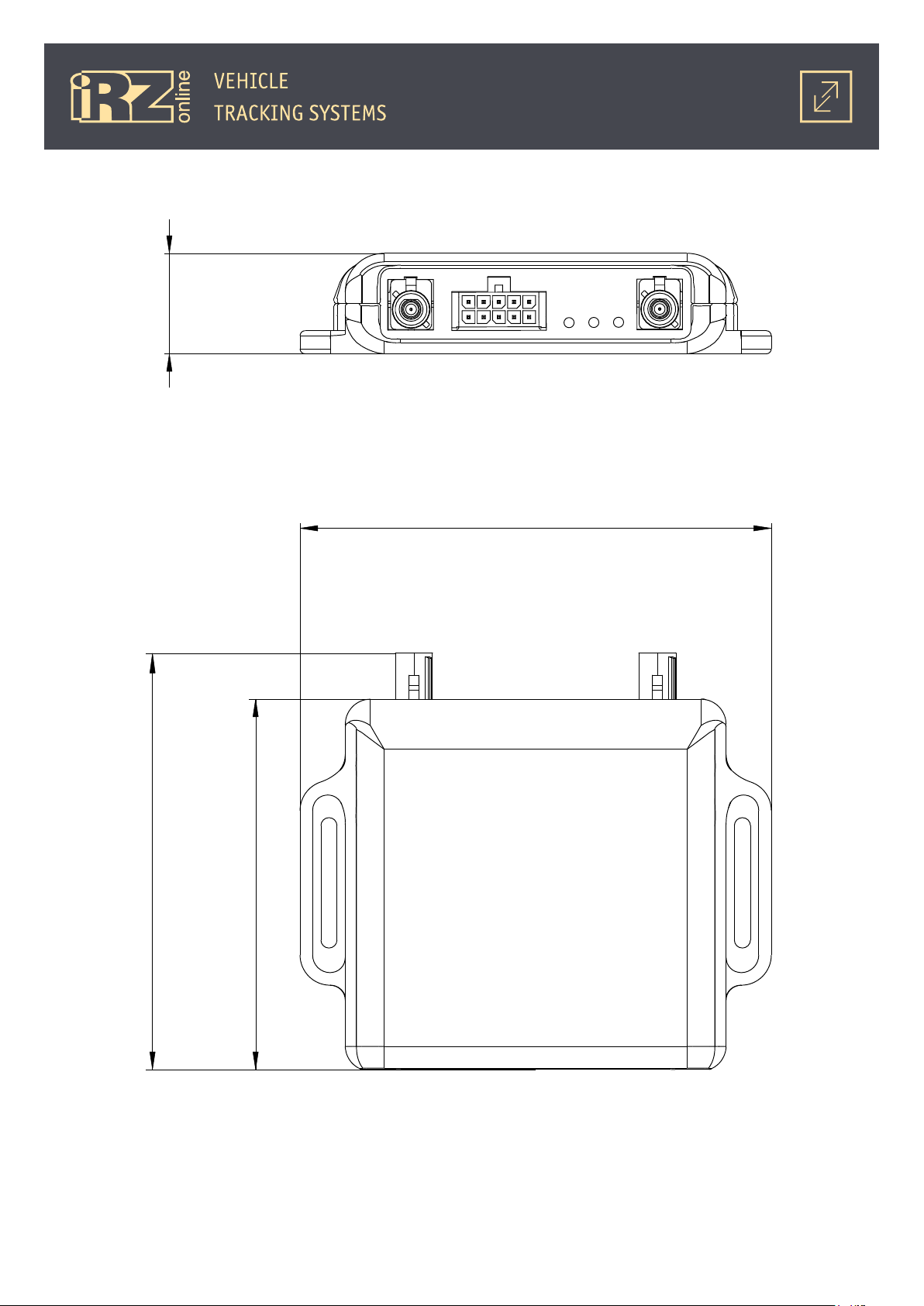
1.5. Dimensional Drawing
20
93,8
83
73,6
Fig. 1.5. iON FM navigation terminal dimensional drawing
21
 Loading...