

iRUGGY
G10/G10s Mobile Tablet
User Manual
Version 1.7
September 25, 2017

G10/G10s User Manual 2
Copyright
Copyright 2017
All Rights Reserved
Manual Version 1.7
The information contained in this document is subject to change without notice.
We make no warranty of any kind with regard to this material, including, but not limited to, the implied
warranties of merchantability and fitness for a particular purpose. We shall not be liable for errors
contained herein or for incidental or consequential damages in connection with the furnishing,
performance, or use of this material.
This document contains proprietary information that is protected by copyright. All rights are reserved.
No part of this document may be photocopied, reproduced or translated to another language without
the prior written consent of the manufacturer.
Trademark
The material in this manual is subject to change without notice. Bluetooth is a registered trademark of
Bluetooth SIG. Microsoft® and Windows® are either registered trademarks or trademarks of Microsoft
Corporation.
All other product or service names are the property of their respective owners.
Safety
Regulatory Information
Caution: Only use approved and UL Listed accessories, battery packs and battery chargers. Do NOT
attempt to charge damp/wet mobile computers or batteries. All components must be dry before
connecting to an external power source.
Power Supply
Use only the approved power supply shipped with the unit. Use of an alternative power supply will
invalidate any approval given to this device and may be dangerous.
Warning for Use of Wireless Devices
Please observe all warning notices with regard to the usage of wireless devices.
Potentially Hazardous Atmospheres
You are reminded of the need to observe restrictions on the use of radio devices in fuel depots,
chemical plants, etc., and areas where the air contains chemicals or particles (such as grain, dust, or
metal powders) and any other area where you would normally be advised to turn off your vehicle
engine.
Confidential and Proprietary Information

G10/G10s User Manual 3
Safety in Aircraft
Switch off your wireless device whenever you are instructed to do so by airport or airline staff.
Pacemakers
Pacemaker manufacturers recommend that a minimum of 15cm (6 inches) be maintained between a
handheld wireless device and a pacemaker to avoid potential interference with the pacemaker. These
recommendations are consistent with independent research and recommendations by Wireless
Technology Research.
Persons with Pacemakers
Persons with pacemakers should ALWAYS keep the device more than 15cm (6 inches) from their
pacemaker when turned ON and hence they should not carry the device in a breast pocket. They should
use the ear furthest from the pacemaker to minimize the potential for interference. If you have any
reason to suspect that interference is taking place, turn OFF your device.
Hearing Aids
The wireless device may interfere with some hearing aids. In the event of interference you may want to
consult your hearing aid supplier to discuss solutions.
Other Medical Devices
Please consult your physician or the manufacturer of the medical device, to determine if the operation
of your wireless product may interfere with the medical device.
FCC/EU RF Exposure Guidelines
FCC Statement
This equipment has been tested and found to comply with the limits for a Class B digital device,
pursuant to part 15 of the FCC Rules. These limits are designed to provide reasonable protection against
harmful interference in a residential installation. This equipment generates, uses and can radiate radio
frequency energy and, if not installed and used in accordance with the instructions, may cause harmful
interference to radio communications. However, there is no guarantee that interference will not occur
in a particular installation. If this equipment does cause harmful interference to radio or television
reception, which can be determined by turning the equipment off and on, the user is encouraged to try
to correct the interference by one or more of the following measures:
- Reorient or relocate the receiving antenna.
- Increase the separation between the equipment and receiver.
- Connect the equipment into an outlet on a circuit different from that to which the
receiver is connected.
- Consult the dealer or an experienced radio/TV technician for help.
This device complies with FCC SAR exposure limits set forth for an uncontrolled environment. This
device complies with Part 15 of the FCC Rules. Operation is subject to the following two conditions: (1)
this device may not cause harmful interference, and (2) this device must accept any interference
received, including interference that may cause undesired operation.
Confidential and Proprietary Information
G10/G10s User Manual 4
Caution!
Any changes or modifications not expressly approved by the party responsible for compliance could void
the user's authority to operate the equipment.
CE Marking and European Economic Area
The use of 2.4GHz RLAN's, for use through the EEA, have the following restrictions:
- Maximum radiated transmit power of 100 mW EIRP in the frequency range 2.400 -2.4835 GHz
- In France, outside usage is restricted to 2.4 - 2.454 GHz.
- Italy requires a user license for outside usage.
Bluetooth® Wireless Technology for use through the EEA has the following restrictions:
- Maximum radiated transmit power of 100mW EIRP in the frequency range 2.400 -2.4835 GHz.
- In France, outside usage is restricted to 10mW EIRP.
- Italy requires a user license for outside usage.
Battery Information
Our rechargeable battery packs are designed and constructed to the highest standards within the
industry. However, there are limitations to how long a battery can operate or be stored before needing
replacement. Many factors affect the actual life cycle of a battery pack, such as heat, cold, harsh
environmental conditions and severe drops. When batteries are stored over six (6) months, some
irreversible deterioration in overall battery quality may occur. Store batteries discharged in a dry, cool
place, removed from the equipment to prevent loss of capacity, rusting of metallic parts and electrolyte
leakage. When storing batteries for one year or longer, they should be charged and discharged at least
once a year. If an electrolyte leakage is observed, avoid any contact with the affected area and properly
dispose of the battery. Batteries must be charged within the 0° to +35°C (32° to 95° F) ambient
temperature range. Replace the battery when a significant loss of run time is detected.
Battery Caution
There is a risk of explosion if the battery is replaced by an incorrect type. Dispose of used battery
according to the local disposal instructions.
Waste Electrical and Electronic Equipment (WEEE)
For EU Customers: All products at the end of their life must be returned to the reseller for recycling.
Confidential and Proprietary Information
G10/G10s User Manual 5
Version
Date
Changes
1.3
Nov 16, 2016
Initial release
1.4
Jan 10, 2017
Updated battery level indicator status definition in 4.6.2
1.5
Apr 24, 2017
Added stylus, mPOS brackets to 1.2 Accessories; removed
references to rotating hand strap (discontinued); aligned 2.3
Specification with current datasheet; updated instruction for
installing mPOS brackets in 5.3; added caution on placing tablet
correctly in the POS dock in 6.3
1.6
July 15, 2017
Added G10s (Cherry Trail), additional ADD-f(x) accessories and
kits. Added section on disabling tactile feedback/vibration
motor. Updated information on Battery Status LED Indicator.
1.7
Sep 25, 2017
Added note regarding power button settings and bridge battery
(4.1.3, 4.7.1), and touch sensor default mode (4.2).
Revision Table
Confidential and Proprietary Information

Table of Contents
1 Unpacking the unit ................................................................................................................................ 8
1.1 Standard items .............................................................................................................................. 8
1.2 Accessories .................................................................................................................................... 8
2 Hardware Overview ............................................................................................................................ 12
2.1 Features ...................................................................................................................................... 12
2.2 System Overview......................................................................................................................... 13
2.3 Specifications G10 G10s ............................................................................................................. 14
3 Product Labelling ................................................................................................................................ 15
4 Basic Operation ................................................................................................................................... 16
4.1 Power On/Off Button .................................................................................................................. 16
4.1.1 Turning on the Unit ............................................................................................................. 16
4.1.2 Turning off the Unit ............................................................................................................. 16
4.1.3 Turning off the Display Backlight ........................................................................................ 16
4.2 in4Touch™ Touch Mode Control Button .................................................................................... 16
4.3 Adjusting Screen Brightness........................................................................................................ 17
4.4 Adjusting System Volume ........................................................................................................... 17
4.5 Programmable Function Key ....................................................................................................... 17
4.6 Charging the Battery ................................................................................................................... 17
4.6.1 Charging via Cable to AC Adapter ....................................................................................... 17
4.6.2 Battery Level Indicator on Tablet ........................................................................................ 18
4.6.3 Battery Charge Level Indicator on Battery .......................................................................... 18
4.7 Replacing the Battery .................................................................................................................. 19
4.7.1 Removing the Battery ......................................................................................................... 19
4.7.2 Installing the Battery ........................................................................................................... 19
5 Installation and Setup ......................................................................................................................... 20
5.1 System Software ......................................................................................................................... 20
5.2 Attaching the Hand Strap ............................................................................................................ 20
5.3 Disabling Tactile Feedback .......................................................................................................... 20
5.4 Installing a microSD card or Micro SIM for 3G or LTE data ......................................................... 21
5.5 Installing ADD-f(x)™ Modules ..................................................................................................... 21

G10/G10s User Manual 7
5.6 Attaching an mPOS Integration Bracket ..................................................................................... 22
6 Using the G10 POS Docking Station .................................................................................................... 23
6.1 Connecting to Power ................................................................................................................... 23
6.2 Connecting to Network and Peripherals ..................................................................................... 23
6.3 Placing the Tablet in the Dock .................................................................................................... 24
6.4 Installing the LCM Customer Display .......................................................................................... 25
6.5 Installing a third-party payment device ...................................................................................... 26
7 Using the G10 VESA Mount................................................................................................................. 27
8 Using the G10 Vehicle Mount ............................................................................................................. 28
9 Software Configuration ....................................................................................................................... 29
9.1 Integrated NFC reader tags supported: ...................................................................................... 29
Confidential and Proprietary Information
G10/G10s User Manual 8
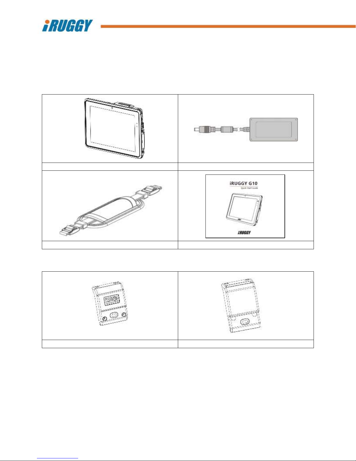
Tablet
AC Adapter
Standard Hand Strap
Quick Start Guide
1D/2D Barcode Scanner ADD-f(x) Module
Long Range Scanner ADD-f(x) Module
1 Unpacking the unit
The following items may be shipped with each unit.
1.1 Standard items
1.2 Accessories
Confidential and Proprietary Information
G10/G10s User Manual 9
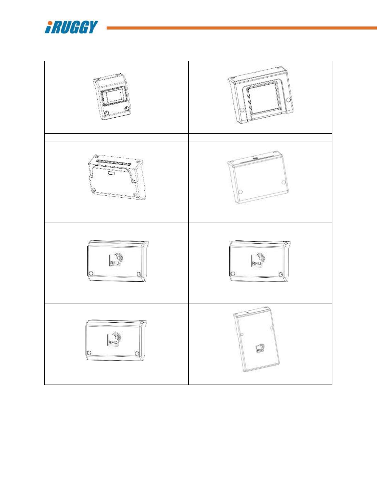
Fingerprint Reader ADD-f(x) Module
Dual Fingerprint Reader ADD-f(x) Module
MSR / Smart Card Combo ADD-f(x) Module
Contact Smart Card Reader ADD-f(x) Module
NFC (HF RFID) Reader ADD-f(x) Module
Dual SAM Reader ADD-f(x) Module
LF RFID Reader ADD-f(x) Module
UHF RFID Reader ADD-f(x) Module
Confidential and Proprietary Information

G10/G10s User Manual 10
LAN & COM IO ADD-f(x) Module
2mm Tip Stylus
G10 mPOS Integration Bracket Mounting Plate
mPOS Integration Bracket for Ingenico iCMP
mPOS Integration Bracket for Verifone e355
mPOS Integration Bracket for Miura M010
G10 POS Docking Station
POS Dock Mounting Arm
Confidential and Proprietary Information

G10/G10s User Manual 11
POS Dock LCM
7” USB Display and Adapter Plate
G10 VESA Mount
G10 Vehicle Mount
Confidential and Proprietary Information

G10/G10s User Manual 12
1
2MP webcam
2
Programmable capacitive function key
3
Battery status indicator
4
Ambient light sensor
5
Touch screen
6
Kensington lock slot
7
ADD-f(x) expansion module bays (3)
8
AF camera with LED flash
9
Battery
10
Battery release latch
11
Speakers (2)
12
DC-in
13
Docking connector
14
Access cover for 3G/LTE, microSD slots
15
Stylus port
16
Access cover for USB 2.0, Micro USB
(OTG) and Micro HDMI port
17
Location of internal NFC reader
18
Audio jack
19
in4Touch™ touch mode control
20
Power On/Off
21
Microphone
Front View
Back View
2 Hardware Overview
2.1 Features
Confidential and Proprietary Information

G10/G10s User Manual 13
2.2 System Overview
Confidential and Proprietary Information

G10/G10s User Manual 14
Touch Display
10.1” (1920 x 1200 resolution) projected capacitive multi-touch display
User-selectable touch mode for Hand, Glove, Stylus or Rain
Programmable capacitive function key on front-bezel
Processor
G10: Intel® Quad-Core 1.83GHz Intel® Quad-Core 2.56GHz
Operating systems
Windows® 10 IoT Enterprise for Tablet
G10: Android™ 4.4.4 Android™7.0
Memory / Storage¹
2GB DDR3L memory / 64GB storage 4GB DDR3L memory / 64GB storage
(Android Model: 32GB) (Windows and Android)
microSDXC socket for expansion
Camera
5MP AF rear camera with LED flash 8MP AF rear camera with LED Flash
2MP front-facing camera
Expansion I/O ports
USB 2.0
Micro HDMI
Micro USB (supports OTG)
Additional peripheral I/O available through optional POS Docking Station
Audio
1W stereo speakers
Audio jack
Microphone
Communications
WLAN 802.11 ac
Bluetooth 4.0 + LE (class 2)
NFC contactless card reader
3G data² and dedicated GPS (factory option) LTE data² and dedicated GPS (factory option)
Power Supply
3.7V 8000 mAh battery, hot swappable* with up to 8 hours per charge³
DC-in, with external AC adapter (Output 5V DV, 4A, Input 100-240VAC, 50/60Hz) for
charging
Environmental
IP65 rated protection from liquid and dust ingress
Designed to MIL-STD-810G 1.2M drop specification
Operating temperature: -10°C ~ 50°C (14°F ~ 122°F);
max. 35°C (95°F) when charging battery
Storage temperature: -20°C ~ 70°C (-4°F ~ 158°F)
Humidity: 90% RH non-condensing
Dimensions (W x H x D)
227 x 185 x 20 mm (10.9” x 7.3” x 0.78”)
Weight (with Battery)⁴
997g (2.19 lbs)
ADD-f(x) modules⁵
1D/2D optical barcode scanner, 1D/2D long range scanner
Fingerprint readers
LF, NFC (HF), UHF RFID readers
Contact smart card reader (EMV Level 1 and 2 certified) and 3 track encrypted MSR
Rear mounting bracket for mPOS devices
LAN and COM I/O Module
Optional accessories⁵
POS docking station (1x LAN, 3x USB 2.0, 1x COM, 1x CD)
VESA charging mount
Vehicle charging mount
2m tip stylus
2.3 Specifications G10 G10s
1 1GB=1 billion bytes; actual formatted capacity will be less
2 Subject to service provider’s broadband subscription and coverage area; additional charges may apply
3 Standard configuration with Intel Z3735F CPU, 2GB memory and 64GB eMMC tested using PCMark® 8 battery life benchmark. Results may be used for product
comparison and may vary under different situations including hardware configuration, software, operating conditions, power management settings and other
factors. Battery life will decrease with time and use
4 Weight shown represents base configuration with battery, excluding any optional accessories
5 Accessories may vary depending on your configuration. Accessories are sold separately
*Hot swappable feature is only available with 3G or LTE data communication and dedicated GPS option.
Confidential and Proprietary Information

G10/G10s User Manual 15
Product
certification
label
3 Product Labelling
Safety certification and other compliance labels may be found on the inside of the battery
compartment, along with product serial number and Windows license sticker. See section on Removing
the Battery for instructions on removing the battery module to view this information.
All tablets are labelled with a unique serial number. This number is important in tracking units through
production and shipment and may be required for servicing the product under the warranty.
Confidential and Proprietary Information

G10/G10s User Manual 16
4 Basic Operation
4.1 Power On/Off Button
Power On/Off button
in4Touch™ touch mode control button
4.1.1 Turning on the Unit
Press and hold the power button down to turn on the system. Release the button once you feel the
vibration. NOTE: The tablet must be docked, plugged into AC or battery charged before turning on the
unit for the first time.
4.1.2 Turning off the Unit
The unit should be shut down normally via the operating system. To force shutdown and manually
power off the unit, press and hold the power button for 5 seconds or longer.
4.1.3 Turning off the Display Backlight
System settings can be used to turn off the backlight automatically for power savings when the system is
idle. When the unit is powered on, pressing the power button momentarily will turn off and on the
backlight unless power button settings have been changed by the user. NOTE: If the tablet is equipped
with a backup battery, keep factory default power button setting (Sleep) unchanged to prevent autoshutdown when hotswapping the main battery module.
4.2 in4Touch™ Touch Mode Control Button
Press and hold the in4Touch button to display and cycle through a menu of graphic icons representing
four different modes for touch operation. Once the icon for desired touch mode is highlighted, release
the button to activate that touch mode and exit the menu.
Hand Supports normal touch operation using a bare finger. This mode is the default mode;
system will automatically return to this mode after cold reboot.
Glove Enables touch operation when the user is wearing gloves.
Stylus Restricts input to stylus, ignoring finger or palm contact. Must be used with a G Series
stylus connected to the stylus port on the tablet.
Rain Supports touch operation using bare finger while reducing interference from random
drops of liquid on the screen.
Confidential and Proprietary Information

G10/G10s User Manual 17
4.3 Adjusting Screen Brightness
Windows display settings allow screen brightness to be set manually or adjusted automatically for
power savings or for comfort under different lighting conditions. There are 4 manual settings: 100%,
75%, 50% and 25%. Factory default setting for the display is fixed at 100% brightness.
An ambient light sensor located on the front of the display may be used to sense and reduce the
brightness level for comfort in low light environments. This feature is disabled at the factory but can be
enabled through system software settings.
4.4 Adjusting System Volume
Volume levels on the integrated dual stereo speakers and devices connected through the audio jack
must be set manually through Windows or Android system software settings.
4.5 Programmable Function Key
The capacitive button on the top right of the tablet display is activated by touch. For Windows and
Android models, this button is pre-programmed in the factory as the Windows or Home key, but the
button may be re-programmed by the user to open applications or access specific functions. For
information on re-programming this key, contact your iRuggy Systems authorized distributor or reseller.
4.6 Charging the Battery
The G10 Mobile Tablet is equipped with an interchangeable 8000mAH battery module supporting up to
8 hours per charge depending on usage.
4.6.1 Charging via Cable to AC Adapter
The battery may be charged by connecting the supplied AC power adaptor directly to the DC-in
connector located on the bottom of the tablet. Pull the protective rubber seal out to plug the cable
directly into the connector. Then plug the adaptor directly into an AC outlet.
Confidential and Proprietary Information

G10/G10s User Manual 18
4.6.2 Battery Level Indicator on Tablet
A battery level indicator LED on the front of the tablet signals charge status:
GREEN Battery charge level at 95% or higher (Tablet is plugged in or placed in dock)
ORANGE Battery is charging (Tablet is plugged in or placed in dock)
RED/Flashing Battery level below 15%
RED Battery level below 10%
4.6.3 Battery Charge Level Indicator on Battery
With the battery module removed from the unit, press the icon shown above. The row of LEDs will light
up for 3-4 seconds indicating battery charge level as follows:
No charge (No LEDs lit)
< 10% charged (Single flashing LED)
11-24% charged (1 LED on)
25-49% charged (2 LEDs on)
50-74% charged (3 LEDs on)
75-100% charged (All LEDS on)
Confidential and Proprietary Information

G10/G10s User Manual 19
4.7 Replacing the Battery
4.7.1 Removing the Battery
Unless the tablet is equipped with a bridge battery supplied on LTE or 3G-enabled models, always power
down the system first. Unplug the AC cable if connected directly to the DC-in port on the tablet. Place
the tablet face down on a flat surface. Next, slide the latch down as shown to unlock and release the
battery module so it can be lifted out of the unit.
If the tablet is equipped with a bridge battery, the system will automatically enter Connect Standby
Mode and turn off the screen backlight. The battery level indicator LED on the front bezel will flash and
the system will beep every 3 seconds for the first 3 minutes. After 3 minutes, the LED will flash and a
beep will sound every half second. System will automatically shut down at 4 minutes.
NOTE: If the tablet is equipped with a backup battery, keep factory default power button setting (Sleep)
unchanged to prevent auto-shutdown when hotswapping the main battery module.
4.7.2 Installing the Battery
Angle the battery module so that the left side with exposed connector pins is inserted first into the
battery compartment. The press the battery into place and slide the latch upward to lock the battery
module back into position.
Confidential and Proprietary Information

G10/G10s User Manual 20
5 Installation and Setup
5.1 System Software
System is factory-installed with the supported Windows or Android operating system and required
drivers for most device options, whether or not the device is installed on the unit when shipped. No
additional software or device drivers must be installed to begin using the system.
On initial bootup of a system loaded with Windows, the Windows activation screen will show and
prompt the user through the activation process.
See section on Software Configuration for more information on drivers supplied with the system.
5.2 Attaching the Hand Strap
Use of the standard hand strap shipped with the tablet is optional. Depending on the situation, the user
may attach the hand strap between any two of six anchor points across the top or either side of the
tablet. To attach the strap to the tablet, thread both ends of the strap into an anchor point, fold back
and tighten in the plastic buckle. Any excess length can be tucked into the sleeve handle at the center of
the strap.
5.3 Disabling Tactile Feedback
By default, the vibration motor is enabled to provide tactile feedback during touch operation. If desired,
vibration can be disabled in the system BIOS settings.
To access BIOS settings, plug a keyboard into the USB port on the tablet, dock or mount and boot up the
system while pressing the Delete key.
When the BIOS main menu appears, touch to open the Setup Utility. Select Advanced to display the
Vibrator Control setting. Touch the setting to change the value to Disabled. Finally, touch the F10 or
ESC button on the touchscreen or keyboard to save and exit. The vibration motor will be disabled upon
completing boot into Windows or Android and will remain disabled the next time the system is
restart. To re-enable the vibration motor, simply repeat the steps above and change value back to
Enabled.
Confidential and Proprietary Information

G10/G10s User Manual 21
5.4 Installing a microSD card or Micro SIM for 3G or LTE data
The user may install a user-supplied SDXC or compatible microSD card on the unit to load or save files,
or expand working data storage capacity. On select tablet models configured for 3G or LTE data
communication, a separate slot is available for installing a user-supplied Micro SIM card.
To install either type of card, first power down the system. Both slots are accessed by removing the two
screws securing a protective, watertight seal located on the bottom of the tablet.
Orient either card so that the gold contact edge faces down towards the front of the tablet. Slide the
card in until it clicks in place. To remove the card, press the outer edge to click and release the card.
5.5 Installing ADD-f(x)™ Modules
Optional ADD-f(x) modules are available to expand tablet functionality. To install any module, first
power down the system. Locate the three universal expansion bays on the top, back side of the tablet.
Depending on the number and size of the modules selected, one or all three bays may be used to install
1, 2 or up to 3 ADD-f(x) modules.
Remove the two screws and lift off the plastic cover covering each bay. This cover may be saved or
discarded. Slide the module in place and fasten in place with the four screws provided with the ADD-f(x)
module kit
Confidential and Proprietary Information

G10/G10s User Manual 22
5.6 Attaching an mPOS Integration Bracket
Custom brackets are available for on-tablet integration of third-party mobile point-of-sale (mPOS)
payment devices, such as the Ingenico iCMP.
To attach the bracket, place the tablet face down. Position the universal G10 mPOS Mounting Plate over
the battery module as shown and attach with the four screws provided (you may need to first remove
and discard cosmetic rubber covers placed over the screw holes).
Use another set of two screws provided to attach the device-specific bracket to the mounting plate.
The mPOS device may slide into the bracket from the top or bottom, depending on design. Charging
port will remain accessible to allow connection of a charging cable (supplied by the vendor) without
removing the device from the tablet.
Confidential and Proprietary Information

G10/G10s User Manual 23
6 Using the G10 POS Docking Station
An optional countertop mount is available to allow the G10 tablet to be operated at different angles
when docked for charging, LAN communication and/or connection with wired peripherals. The docking
station also supports optional mounting of an LCM or 7” customer display or third-party payment
terminal.
6.1 Connecting to Power
Before the docking station can be used to charge the tablet or connect to peripherals, the dock must be
connected to AC power via the 19V/65W AC adaptor shipped with the dock. Locate the DC-in connector
on the dock and plug in the power cable from the AC adaptor.
6.2 Connecting to Network and Peripherals
Disconnect the power cable from the docking station. Plug network or peripheral cables into available
ports located in the base:
RJ45 10/100 Ethernet LAN
Cash drawer port, 12V or 24V selectable through jumper settings (default 24V)
One RJ45 RS-232 port, 0V, 5V or 12V selectable through jumper settings (default 0V)
Three 5V USB 2.0 ports
Confidential and Proprietary Information

G10/G10s User Manual 24
Open
position
Locked
position
Tab on
POS Dock
Extension
on tablet
6.3 Placing the Tablet in the Dock
The tablet may be placed on the dock either powered on or
off.
NOTE: When placing the tablet on the dock, take care to
locate the extension on the back center of the tablet and
make sure this slides over and covers the tab on the dock. If
this tab is not engaged as shown below, the docking
connection will be loose and the tablet may not charge or
connect to LAN or peripherals.
There is a latch mechanism to secure the tablet in the dock, accessed on the back of the mount. Before
placing the tablet in the dock, check to make sure the latch is in the open position.
When removing the tablet from the dock, you may encounter some resistance as there is a strong
magnet to hold the tablet firmly in place and ensure docking connectors remain in contact during
operation.
Confidential and Proprietary Information

G10/G10s User Manual 25
6.4 Installing the LCM Customer Display
An optional 2 line x 20 graphic LCM customer display may be mounted on the back of the docking
station. Contact your iRuggy Systems or authorized sales representative for a copy of the separate user
guide and OPOS driver for the customer display option.
To install the customer display, remove the single screw securing a cover over the rear mount area and
discard.
Thread the customer display cable through the opening and fasten the display mount into place with the
four screws provided. Connect the host end of the cable to any of the available USB ports.
Confidential and Proprietary Information

G10/G10s User Manual 26
6.5 Installing a third-party payment device
An optional mounting post is available to attach a third-party payment device or 7” USB Display on the
back of the docking station. The post is compatible with device-specific mPOS brackets supplied by
iRuggy Systems.
To install the device mount, remove the screw and discard the blanking cover over the rear mount
access (see previous section). Attach the post to the base with the four screws provided before
attaching the iRuggy Systems mPOS bracket.
Confidential and Proprietary Information

G10/G10s User Manual 27
DC-in
Latch
USB
7 Using the G10 VESA Mount
An optional fixed position mount is available to operate the tablet while charging. This mount features a
75 x 75 mm VESA hole pattern for attaching the mount to any VESA compatible wall or post bracket.
The AC adapter shipped with the tablet may then be plugged directly into the DC-in connector on the
charging dock. A PC USB port is also available on the dock.
The tablet may be placed on the dock powered on or off. The G10 VESA Mount includes a latch
mechanism to hold the tablet securely in position, similar to the G10 POS Docking Station. See
illustration in Section 6.3 for illustration on engaging and disengaging the latch.
Confidential and Proprietary Information

G10/G10s User Manual 28
Thumb
screw
DC-in
USB
Latch
8 Using the G10 Vehicle Mount
An optional vehicle mount is available to secure the tablet onto a vehicle-specific bracket. This mount
features a 75 x 75 mm VESA hole pattern. A cigarette lighter adapter shipped with the vehicle mount is
plugged into the mount and standard cigarette lighter outlet to keep the tablet charged. The vehicle
mount also features a 5V PC USB port to connect a USB device.
To mount the tablet, lift the top frame and place the tablet into the base at an angle. Push the frame
down and fasten the rear latch to secure the top frame into position. Align and tighten the thumbscrew
to hold the tablet firmly in place.
Confidential and Proprietary Information

G10/G10s User Manual 29
9 Software Configuration
System is factory-installed with the supported Windows or Android operating system and required
drivers for most device options, whether or not the device is installed on the unit when shipped. No
additional software or device drivers must be installed to begin using the system.
Contact your iRuggy Systems authorized distributor or reseller for technical information required for
software integration or specific device configuration. Most answers can be found in iRUGGY Tech Notes
created for reference by system integrators or software developers.
9.1 Integrated NFC reader tags supported:
All G10 models ship with an integrated NFC reader, with read-only support for the following tag types:
NXP Mifare Ultralight
NXP DESFire
Sony FeliCa
Broadcom Topaz
Confidential and Proprietary Information
 Loading...