

Page 1
Hardware Guide
WiFi
Version 2013.02
Page 2
The following produtc
Is conrmed to comply with
Hardware Guide WiFi
EG Declaraon of Conformity
IRTrans WiFi
DIN EN 55024: 1998 + A1: 2001 + A2: 2003 .
2
©2012 IRTrans GmbH
Page 3

Hardware Guide WiFi
Contents
1. IRTrans WiFi / WLAN .................................................................. 4
1.1 Connections ..................................................................................... 4
1.2 Power supply .................................................................................... 4
1.3 USB connection / installing drivers ................................................... 5
1.4 Settings / startup .............................................................................. 5
1.5 Web Interface ................................................................................... 6
1.6 Jumpers ............................................................................................ 7
2. External IR Transmitters ............................................................ 10
3.1 stick on minitransmitters ................................................................... 10
3.2 external high power transmitters ...................................................... 10
3.3 Devices with 2X option ..................................................................... 11
3. Connecting external IR receivers.............................................. 11
4. RS232 interface ........................................................................... 11
© 2012 IRTrans GmbH
3
Page 4
Hardware Guide WiFi
1. IRTrans WiFi
The IRTrans WiFi is an IR transceiver with WLAN (IEEE 802.11bgn) interface.
Basic features include:
Receive and transmit IR
1 output for external IR transmitters
1 input for external IR Empfängers
WLAN (IEEE 802.11bgn)
USB connection for configuration
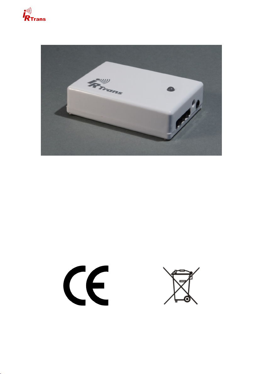
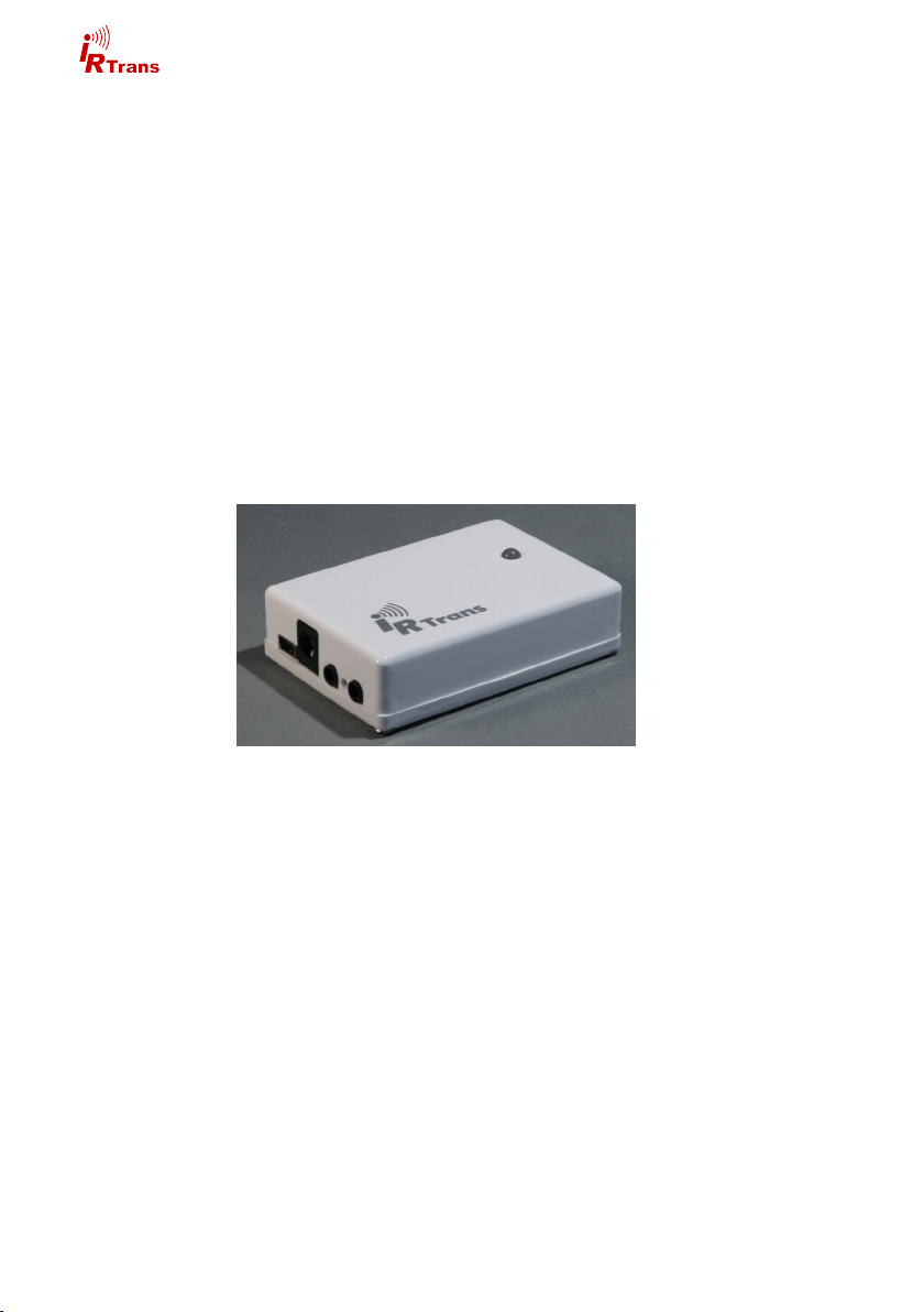
1.1 Connections
On the back there are left to right:
IRTrans WiFi back
USB connector (Mini USB)
Connector for power supply
2nd output (not active without 2X option)
WLAN Status LED
1st output
The left 3,5mm jack is present on all IRTrans devices but not active unless a second output (2X option) or bidirectional RS232 option is installed.
1.2 Power supply
The IRTrans Ethernet is powered by an external power supply. It must deliver 8-
16V and 300mA per IRTrans device. The positive lead is wired to the center ter-
minal of the 5,5/2,1mm hollow connector. Powering the IRTrans by USB is not
possible.
4
©2012 IRTrans GmbH
Page 5

Hardware Guide WiFi
1.3 USB connection / installing drivers
The IRTrans WiFi is equipped with a mini USB connector for configuration and
firmware updates.
IPAssign does not work with IRTrans WiFi. Use USB for configuration.
Before connecting the IRTrans to the PC the software / drivers must be
installed.
Windows 2000 / XP / Server 2003 / Vista / 7
IRTrans USB drivers are digitally signed and included in the IRTrans software
installer (setup.exe). Futhermore the drivers are available from the Microsoft driver database as well.
After connecting the IRTrans driver installation will start automatically.
Linux / MAC
Drivers and the configuration software are located on the cd in the folder linux or
mac respectively or can be downloaded from the IRTrans website. This software
requires Java JRE 1.6 or later.
1.4 Settings / Start-Up
For the first start-up the IRTrans WiFi has to be configured by USB.
For this purpose use the configuration software „IRConfig. The WLAN settings
are available through the tab „WLAN / IP“. Most important are „SSID“, „WLAN
Preshared Key“ and DHCP or fixed IP as applicable.
After writing these settings to the device it will try to start the WLAN connection.
Color codes for the WLAN status LED are:
off: WLAN deactivated / not configured
Solid red: no WLAN connection
Solid green: WLAN connection
Flashing green: transferring data
Flashing red: error during connection
© 2012 IRTrans GmbH
5
Page 6

Hardware Guide WiFi
WLAN troubleshooting
In most cases the WLAN connection will work after entering SSID and Key. Here
are a few tips in case there is a connection problem:
Sometimes there are problems with access points that have a hybrid B/G
mode. In this case select either B or G.
Selecting a lower speed in the WLAN settings also helps sometimes.
Using a fixed IP instead of DHCP sometimes solves problems as well.
If there is an error with the WLAN connection there will be an error code displayed in the configuration dialogue:
Error 1-3 Error initialising the radio module (Hardware problem)
Error 4 Error scanning available WLANs
Error 5 Error reading parameters of the radio module
Error 6/7 Error setting WLAN parameters (SSID/Channel)
Error 8 Error setting the WLAN Key
Error 9 Error connecting to the WLAN
Error 10 Error setting the IP Parameter
Error 11-14 Error opening the TCP / UDP sockets
Error 15 Error verifying the IP parameters
Error 16 connection aborted by USB access
1.5 Web Interface
First configuration has to be done by USB.
Once the IRTrans is accessible by network further configuration can be done
using the integrated web interface. Additionally the IRTrans software may be
used via network as well as USB.
IRTrans devices with Ethernet offer a browser based configuration interface. All
parameters that can be altered by the web interface can be accessed by the IRTrans servers device status dialogue as well.
To access the web interface simply type the IP adress of the IRTrans in an internet browser:
http://192.168.0.32
The adress will chance according to your network settings.
6
©2012 IRTrans GmbH
Page 7

Hardware Guide WiFi
Now you will see the Login page:
To access the configuration enter username and password. The default password is::
username: admin
password: irtrans
This password may be changed by clicking „Change Password“
All options accessible through the webinterface are identical to the corresponding
options of the device status. For a detailed description refer to the software handbook.
1.6 Jumpers
Inside the IRTrans WiFi there are several jumper for configuration purposes. These will be set by factory and must not be altered.
Changing jumper settings inside the IRTrans will not activate additional
features. It may however result in the IRTrans not working correctly anymore.
© 2012 IRTrans GmbH
7
Page 8

Hardware Guide WiFi
The IP Settings dialog to configure
the IP parameter. The following fields
are defined:
Use DHCP: Activates the automatic
IP assignment via DHCP.
Fallback …: When no DHCP server
is available the device falls back to
the default address 192.168.0.32
after 30s.
IP Address: Manually configured IP
address
Subnet mask: Manually configured
IP subnet mask
Default Gateway: Manually configured default gateway
In the lower lines the currently active parameters including the MAC address are
displayed.
The button „Store Configuration“ transfers all values to the non-volatile EEPROM
of the device.
The Access Rights dialog configures the access rights of the device. If no values
are entered here, any client can access the device. As soon as at least one value
is entered only clients that fit into at least one of the entries are allowed to access
the device.
Each entry consists of an IP address
and a subnet mask: 192.168.0.0 /
255.255.255.0 enables all clients
within the network 192.168.0.x. An
entry 192.168.0.1 / 255.255.255.255
allows only one client to use the
IRTrans LAN. The access rights are
active for all TCP and UDP functions.
To avoid a complete lock-out it is always possible to access the web front end
from within the local network of the device – even if there is no entry for that subnet.
8
©2012 IRTrans GmbH
Page 9

Hardware Guide WiFi
The IR Relay configuration is used to configure the relaying of IR signals from
one IRTrans Ethernet to another. In general IR signals received by other IRTrans
Ethernet modules will be relayed automatically. This relaying works without a
server – even with IRTrans devices without an integrated IR database. The exact
configuration of the relaying is done in this dialog.
In the list below “Accept IR Relay
from“ all IRTrans IP Addresses can
be entered from which IR relaying
should be enabled. If the list is empty, all signals will be relayed.
The list below “Send IR Relay to“ tells
the system to which devices received
IR codes should be relayed. Normally
it is enough to enable the checkbox
„Broadcast IR Relay“. Only if IR data
should be relayed to routed networks
it is important to enter a target address because broadcasts will not be
routed. The IR receiving of the irserver is also done via that broadcasts.
That means either broadcast has to
be enabled or the address of the host
running the irserver has to be in this
list – otherwise the irserver will not receive IR codes from this IRTrans module.
The UDP Broadcast fields are only used for modules with integrated IR Database. They define to which address and port formatted IR receive data has to be
sent. The precise format of these telegrams is configured via the IR database.
The IR parameters can either be configured using the IRTrans GUI client or
via the webpage “IR Configuration”.
All the fields and their meanings are
explained in detail in the Users manual
for the IRTrans system.
Of course both ways of configuration
can be used alternately.
© 2012 IRTrans GmbH
9
Page 10

Hardware Guide WiFi
2. External IR transmitters
There are a variety of external transmitters available with 3,5mm jacks.
2.1 stick on minitransmitters
The minitransmitters can be sticked directly to the IR receiver of the your devices.
Please note:
The transmitter casing is not transparent all the way around. The transmit-
ters will only work when the paper of the sticker is removed.
Range is limited to 20-30cm (~1ft). The transmitters should be sticked
directly to the IR receiver.
Individual control of multiple external transmitters is not possible with the
IRTrans devices covered by this handbook.
Standard cable length is 1,8m (~6ft). Cables may be extendet to up to 5m
(~15ft). Longer cables may cause signal distortions.
Important: When using external high power transmitters there is a jumper
to enable full power. This jumper must be removed when using minitransmitters.
2.2 external high power transmitters
The external high power transmitters are equal to the built in IR LEDs. They are
available in a high frequency version as well (455kHz). The high frequency transmitters can be recognised by clear LEDs. High power transmitters can be
connected to all of the IRTrans devices.
Cables should not be extended beyond standard length (1,8m~6ft). Longer
cables lead to distorted IR signals.
For using external high power transmitters a jumper has to be set inside the IRTrans. The following pictures illustrate the position of this jumper:
The jumper must not be set when using stick on minitransmitters!
10
©2012 IRTrans GmbH
Page 11

Hardware Guide WiFi
2.3 Devices with 2X option
IRTrans modules with 2X option offer a second independent output for external
transmitters. This is normally done by the 2nd (left) 3,5mm jack. If the IRTrans is
equipped with a RS232 interface the RS232 interface will use the leth jack and
the 2nd IR output is available by stereo plug on the first (right) jack. Note: When
ordering external transmitters this must be taken into account.
3. Connecting external IR receivers
External receivers can be connected by a 3,5mm jack next to the built in IR receiver.
When using an external receiver it must be enabled in the device settings and the
correct receiver type has to be selected.
When using external receivers firstly the receiver must be enabled and
secondly the correct receiver type has to be selected with the IRTrans
software.
4. RS 232 interface
The IRTrans WiFi is available with a bi directional RS232 interface. The active
RS232 cable must be connected to the 2nd (left) output an the IRTrans.
If the IRTrans is equipped with the optional RS232 interface the 2nd IR
output (2X option) will be available by stereo plug using the right 3,5mm
jack.
© 2012 IRTrans GmbH
11
Page 12

 Loading...