

Version 2.12
Users Manual
Users Manual IRTrans Version 2.12
2
EU Declaration of Conformity
For the following products
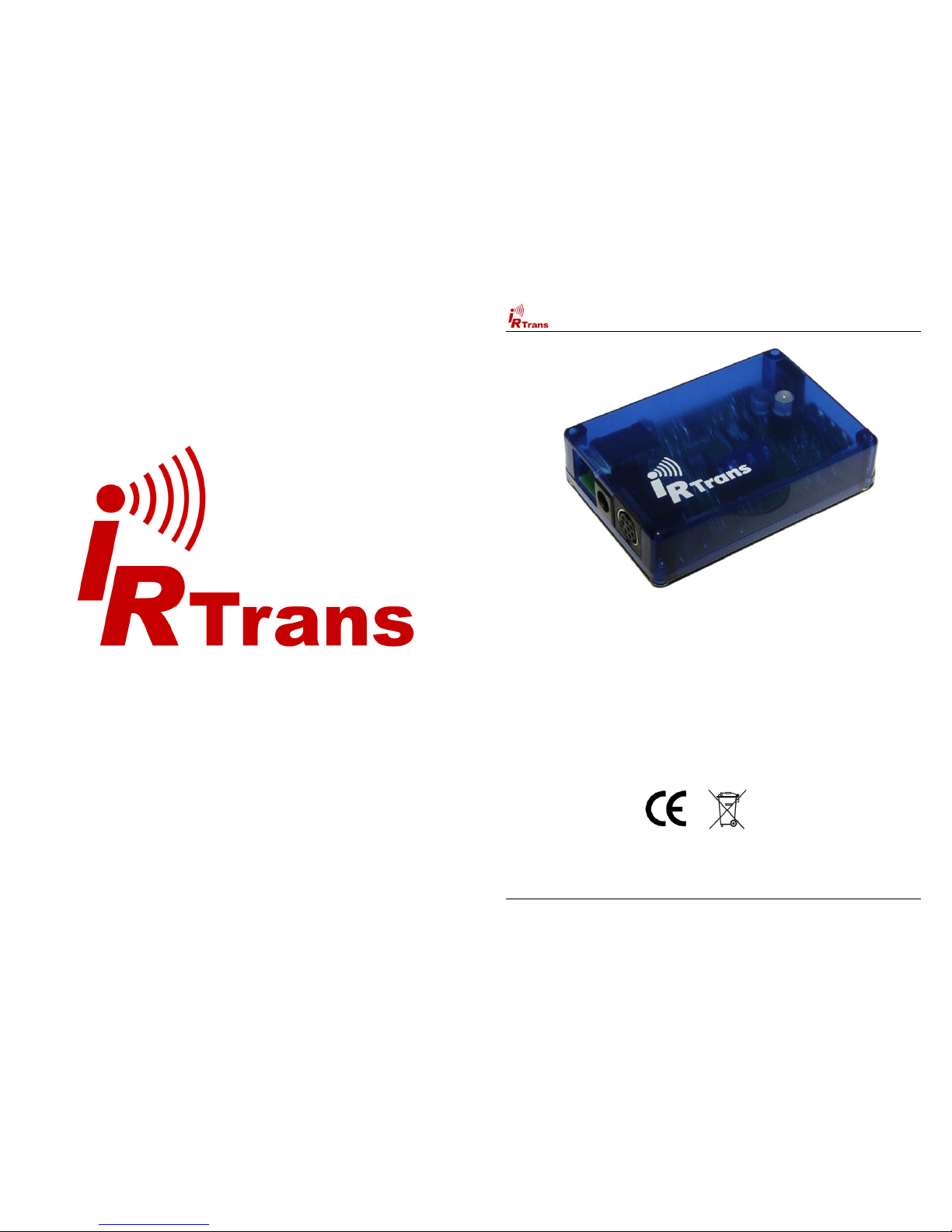
IRTrans USB
IRTrans Serial
IRTrans IR Bus Module
IRTrans Translator
IRTrans Mediacotroller
IRTrans Ethernet / IRDB
IRTrans Ethernet PoE / IRDB
IRTrans LAN Controller
IRTrans LAN Controller XL
we hereby declare that they conform to the declarations regarding Electromagnetic
Compatibility as defined in
EN 55024: 1998 + A1: 2001 + A2: 2003
Users Manual IRTrans System © 2006-2008 IRTrans GmbH
Users Manual IRTrans Version 2.12
3
Table of Contents
1. IRTrans – Quick reference Guide ..................................................................... 5
1.1. Installing the Hardware. .......................................................................... 5
1.2. Installing the Software ............................................................................ 5
1.3. Starting the Server. ................................................................................. 5
2. Installing and connecting the Hardware .......................................................... 6
2.1. General ................................................................................................... 6
2.2. USB Version ........................................................................................... 8
2.3. RS232 Version (with DSUB 9 Connector) .............................................. 8
2.4. RS232 Version (new Versions with Western Plug) ................................ 8
2.5. Connecting the PowerOn Option ............................................................ 9
2.6. Building a multizone system ................................................................. 10
3. USB Driver installation .................................................................................... 11
3.1. Windows 2000 / XP .............................................................................. 11
3.2. Linux ..................................................................................................... 11
4. Installing and using the software ................................................................... 12
4.1. IRTrans Server Software ...................................................................... 12
4.2. Starting and testing the Software ......................................................... 14
4.3. Starting the Server automatically.......................................................... 14
4.4. Format of the IRTrans IR Database ..................................................... 15
4.5. IRTrans GUI Client ............................................................................... 17
4.6. The ASCII / Batch Client (irclient) ......................................................... 24
4.7. Using LIRC Clients ............................................................................... 24
4.8. Girder Plug-in ........................................................................................ 25
4.9. IRTrans and Homeseer ........................................................................ 29
Informations regarding the Macintosh Software can be found in the Manual
shipped with the Macintosh Software.
Damage to the IRTrans, the computer system or even personal property might
arise as a result of not following advices marked by that symbol.
This symbol marks important tips for handling and using the IRTrans system.
All trademarks mentioned herein belong to their respective owners.
Users Manual IRTrans Version 2.12
4
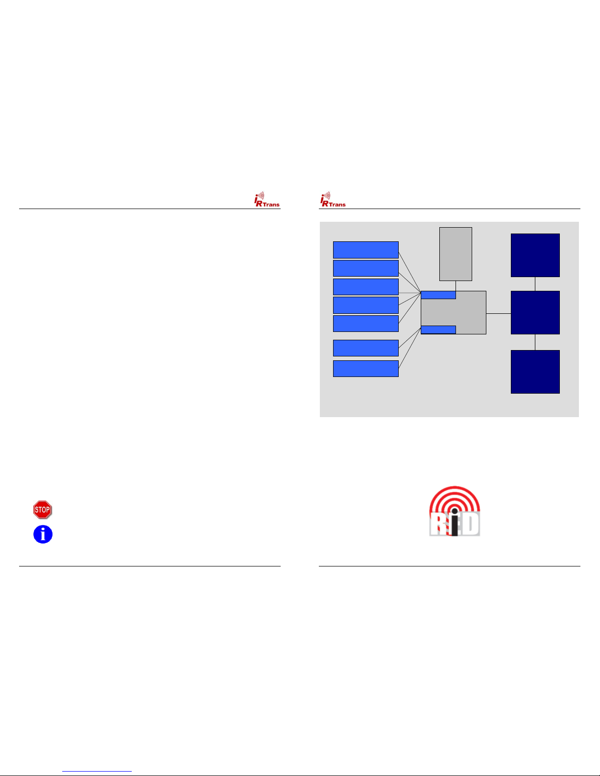
IrTrans Server
(irserver)
Windows or Linux
IRTrans
USB / RS232
IRTrans
LCD
Modul
IRTrans
IR Bus Modul
(max. 16 connected
to the Bus)
IR Data-
base
(ASCII Files)
IRTrans Socket
LIRC Socket
IRTrans Windows Client
incl. Learning of Codes
Other IRTrans
Clients (Win / Linux)
IRTrans
Web Client
LIRC Clients
(VDR, irexec…)
WinLIRC Clients
Girder via Plugin
Homeseer via Plugin
Architecture of the IRTrans System
USB or
RS232
Interface
for the PC
Serial
2 Wire Bus
Serial
2 Wire Bus
Overview of the Architecture of the IRTrans System
The iRed Mac Software uses a different architecture.
Please refer to the iRed Manual for details.
Please note that iRed is distributed exclusively via Download. Download
instructions are part of the iRed License Mail every new customer gets.
Users Manual IRTrans Version 2.12
5
1. IRTrans – Quick reference Guide
1.1. Installing the Hardware
The Installation of the Hardware is described in detail in Chapter 2 of this
manual. When using the USB Version the USB Driver has to be installed,
too. This is also described in detail in the corresponding chapter.
1.2. Installing the Software
! On Windows it is enough to just put the CD into the drive. Windows
now automatically starts the installtion on the CD. In most cases the
default installation is applicable.
! Ob LINUX the script install.sh on the CD has to be started. By default
the software will be installed in the folder /usr/local/irtrans. It can also
be copied to other folders:
cd /cdrom
./install.sh
! Installation Instructions for the Mac can be found together with the
Mac Software.
1.3. Starting the Server
! On Windows the server is started through the Start Menu. The Start
Menu uses the irtranstray utility, that puts the Server in the Windows
Toolbar. Wenn the RS232 Version is not connected to COM1 the
Menu Entry has to be modified accordingly.
! On LINUX the server is started with the command irserver <device>.
Device can either be a serial Port (e.g. /dev/ttyS0) or usb for an USB
Device. If the USB device can not be found automatically your LINUX
distribution uses non-standard USB device files. Then you need to
find out the active USB device node via
cat /proc/bus/usb/devices.
The irserver is TCP/IP based. Therefore it can be accessed by different
Clients that can even be installed on different Systems in a Network. Of
course it can also be accessed via large, routed Networks or even the
Internet. Of course it can be accessed by several Clients at a time that
can run on different Operating Systems.
All IRTrans Clients need a running irserver!
Users Manual IRTrans Version 2.12
6
2. Installing and connecting the Hardware
2.1. General
The DIP Switch is used to set the address of the controller on the serial
bus. The transceiver connected to the PC should have the address “0”.
The address is coded in binary. It is possible to set up to 16 different
addresses. Every Unit should have a unique ID. When a new USB /
RS232 Transceiver (Blue case) is used, the Address is set via Software.
The device connected to the PC should in general have the Address “0”.
All IR Bus Modules have “classic” DIP Switches.
The Ferrite Core shipped with the IRTrans should be attached to the
RS232 / USB Cable as shown in the picture below (it is no longer
needed & shipped for USB Devices with a version >= 3.6) :
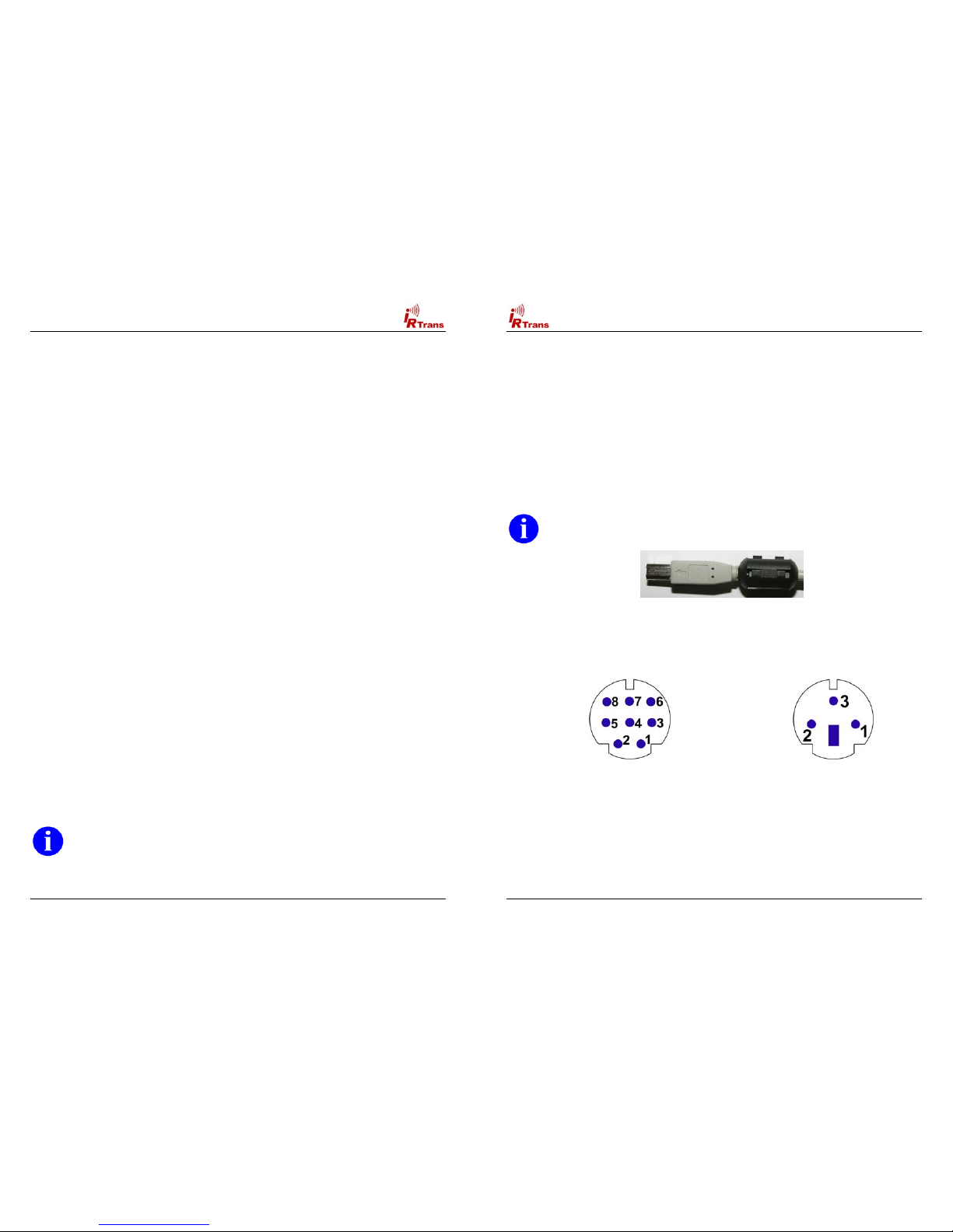
There are two different Mini DIN Connectors used to connect external
devices. The older versions have a 3 Pin connector, the newer ones 8
Pins. Despite from the different pin configuration both versions are
compatible.
Mini DIN 8 Socket Mini DIN 3 Socket
Both Sockets viewed from front
Pin Configuration of the 3pin MiniDIN Socket:
! 1: Masse / GND
! 2: +8 – 16V= Supply Voltage Serial Bus
! 3: Data I/O
Users Manual IRTrans Version 2.12
7
Pin Configuration of the 8pin MiniDIN Socket:
! 1: Masse / GND
! 2: +8 – 16V= Supply Voltage Serial Bus
! 3: Data I/O
! 4: +5V stabilized Voltage (Input)
! 5: Relay Contact PowerOn (1)
! 6: Output for additional IR Transmitter (Anode / +)
! 7: Output for additional IR Transmitter (Cathode / -)
! 8: Relay Contact PowerOn (2)
If the additional 5V Input (Pin 4) is used, care must be taken that only
a stabilized Voltage of 5V is applied. A wrong voltage on that Pin
might destroy the IRTrans.
This Pin can be used to power the IRTrans via the Standby Voltage of an
ATX Power supply. That allows switching on the PC via Infrared together
with the PowerOn Option.
To protect the PC form Short Cuts this Supply Line should be
protected by a fuse.
The output for additional IR Transmitters might get damaged by
Shortcuts or applied voltages. Therefore extra care should be taken
when connecting external Transmitters.
If every Transceiver has its own Power Supply only the Pins 1 & 3 are
needed to make up the Serial Bus. If the Pins 1, 2 & 3 are used only one
IRTrans needs to have a Power Supply connected. It is not possible to
power Transceivers connected to the Serial Bus by the USB or RS232
Interface of the PC.
Every Transceiver connected to the Serial Bus has to be powered.
Otherwise Termination Problems and Malfunctions of the Serial Bus
may arise.
The Power Supply connector is used to Power Bus units or PC Units
while the PC is switched off. The external Power Supply has to deliver 816V= with 50mA for each IRTrans connected to the Bus. The Plus Pole is
the inner contact of that Connector.
Only the DC Connector of the IRTrans should be used to power the
Serial Bus. This connector is protected by an automatic fuse. If the
power is supplied directly into the Serial Bus Cables a fuse should
be used to protect the Bus System from short cuts.
Users Manual IRTrans Version 2.12
8
2.2. USB Version
Before connecting the Device to the PC the Driver CD should be
inserted into the CD Drive.
A USB A-B Cable is used to connect the USB Device to the PC or a USB
Hub. After connecting the PC detects the Device and starts the Driver
installation. The USB Version is always powered by the PC. However, an
external Power Supply might also be connected.
2.3. RS232 Version (with DSUB 9 Connector)
To connect the RS232 version to the PC a simple pass-through RS232
cable is needed. (No Null-Modem!) Baud rate and parameters are set
automatically. To supply power to the IRTrans unit you need a complete
RS232 cable. If an external power supply is used, only GND / RxD / TxD
are needed.
Most PCs deliver enough power using the status lines of the RS232 port
to power the IRTrans even while sending. If you discover problems
sending codes you need to connect an external power supply.
This power supply needs to deliver 8-16V= with about 250mA. The
positive pole has to be connected to the inner contact of the power
connector (as usual). If codes are only received, the power delivered by
the PC should always be enough to power the IRTrans.
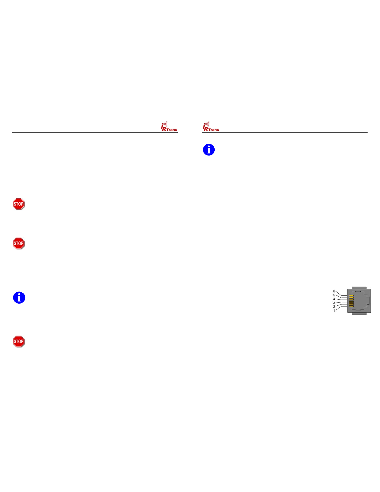
2.4. RS232 Version (new Versions with Western Plugs)
The new serial IRTrans Versions use a 6pin Western Connector to
connect the IRTrans to the PC. This cable has to be configured as
follows:
Signal Pin No. (PC DSUB 9) Pin No. IRTrans
GND 5 5
RTS 7 4
DTR 4 6
RxD 2 1
TxD 3 3
Of course a suitable cable may be ordered.

Users Manual IRTrans Version 2.12
9
If an external power supply is used, only GND / RxD / TxD are needed.
A power supply is needed for the IRTrans RS232 or Mediacontroller.
This power supply needs to deliver 8-16V DC with about 100mA. The
positive pole has to be connected to the inner contact of the power
connector (as usual).
2.5. Connecting the PowerOn Option
An IRTrans Module with PowerOn Option is shipped with a connecting
cable. This Cable can be connected to the Power Switch of the ATX PC.
To do that the cable is to be connected between the Power Switch and
the Main board.
In no case that Contact might be used to switch high current, high
voltage or even Mains!
The additional (isolated) Cable can be used to power the IRTrans with
+5V Standby Voltage. Then no external Power Supply is needed. To
allow that, the ATX Power supply has to deliver at least 1A on the
Standby Line. Unfortunately in most PCs that Voltage is not readily
available on a connector.
That means that a cable must be tapped. That should only be done
when you have the needed equipment (Measurment Tools) and
knowledge. Mistakes when connecting the Module (other Voltages
then 5V) might damage the IRTrans, Short-Cuts might damage the
PC / Power Supply or in the worst case might even cause Fires. To
avoid that, the system should always be protected by a Fuse in the
Cable.
Before making any connections the Mains Connector should always
be removed before making any connections because the Standby
Voltage is present even when the PC is switched off.
If there's any doubt an external Power Supply should be used.
The Software settings to use the PowerOn Options are done in the Status
Page of the GUI or ASCII Client. That is explained in Detail in Chapter 4.5
of this manual.
Users Manual IRTrans Version 2.12
10
2.6. Building a multizone system
The IRTrans System ist used to control larger homes, too. To do that up
to 16 IRTrans devices can be connected using the serial two wire bus.
Cables and infrastructure can be freely chosen, no special cables are
needed.
! The serial bus has been tested with cables up to 30m long.
Depending on the environment larger distances are possible.
However, connecting devices in different buildings is not allowed
without a galvanic isolation of the two devices.
! No special cables are needed. They do not have to be shielded
or twisted. Of course an existing TP wiring can be used.
! The topology can be freely chosen. It is possible to use bus and
star topologies. Even combinations are allowed.
If a three wire bus is used, the supply voltage for all units can be
transferred over the bus, too. Any of the connected units can be used to
power the bus. The power supply has to deliver 8-16V= with about 50mA
for each connected module.
Please also read the general instructions for the IRTrans Bus in
Chapter 2.1.

Users Manual IRTrans Version 2.12
11
3. USB Driver installation
3.1. Windows 2000 / XP
On a windows system you only need to unpack the driver archive into a
folder or just put the software CD into your CD-ROM drive. After
connecting the transceiver you only need to point the operating system to
the driver directory. Using XP it’s even enough to just insert the CD into
the drive. Windows will find the driver there. Using XP the message
informing you, that the driver is not signed can be safely ignored.
3.2. Linux
Starting with LINUX Kernel version 2.6.5 / 2.4.26 the USB drivers for the
IRTrans are included in the standard kernel.
For older versions the files ftdi_sio.c & ftdi_sio.h has to be patched using
the supplied .diff files. The original drivers can be found in the folder
/usr/src/linux/drivers/usb/serial. They can be patched with
# patch p0 < patchfile.diff
Afterwards the ftdi_sio Kernelmodule has to be compiled & installed. Of
course the drivers have to be activated first (see below for details):
# cd /usr/src/linux
# make modules
# make modules_install
In the kernel configuration the following USB drivers have to be activated:
! Usbserio
! FTDI_serio
! USB Subsystem
These drivers should be compiled as modules. If the USB Device daemon
is running the system automatically detects the IRTrans and loads the
correct driver. There are messages in the syslog documenting that
procedure. Now a device will be assigned to the IRTrans (mostly
/dev/ttyUSB0). If other serial USB devices are connected, that device
number may shift. Once more there will be a message in the syslog
showing which device was allocated.
Users Manual IRTrans Version 2.12
12
4. Installing and using the software
4.1. IRTrans Server Software
The IRTrans Software uses a client / server structure. Every command is
processed by the server (irserver). Therefore this server has to run all the
time. Right now there are no clients which connect directly to the IRTrans
hardware. This makes changes in the firmware and protocol a lot easier
as only one application has to be changed. Furthermore every client can
access the server and hardware using any TCP/IP network. Even an
access using the internet or a VPN is possible. Client and server don’t
need to run on the same computer. The installation of the server is very
simple:
On Windows setup.exe on the CD will install the complete IRTrans
Software. Afterwards there will be an entry in the Start Menu to start the
server using the tray utility irtranstray. Of course it is also possible to start
the server directly – then the server will run in an ASCII window.
The irtranstray Program (available only for windows) has got the following
additional functions:
! Diagnostics dialog showing the messages of the server
! List of received IR Codes (for debugging)
! Learning of IR Commands (without Client)
! Reload of the IR Database after manual changes
! Sending of IR Commands
On LINUX the installation script on the CD (install.sh) will copy the LINUX
Software into the folder /usr/local/irtrans. On LINUX the server will be
started in shell window. First the correct device has to be knwon: USB
devices are found automatically using the Pseudo Device “usb”. For serial
devices the port has to be known. The first serial port is /dev/ttyS0.
The command „irserver /dev/tty….“ will now start the server. There will be
some output from the server showing the startup procedure.

Users Manual IRTrans Version 2.12
13
The following command line parameters are supported by irserver (and irtranstray):
-daemon Start irserver in the background (only LINUX). Using Windows
irserver can be started via the autostart folder. See Chapter 4.3
-debug_code All received codes are logged
-hexdump The server prints the complete communication between Server and
Hardware. This can be used to debug codes or to record the
communication to use the IRTrans with other systems.
-hexfile <file> The server prints the complete communication between server and
device into <file>. This can be used to record the communication to
use the IRTrans with other systems.
-baudrate <baud> Use this baudate to communicate with an RS232 module
-http_port <port> Activate the integrated Webserver at port <port>
-learned_only Only Codes that have been learned are transmitted to the Network
clients. NOTE: This option will become default in later versions of the
irserver.
-logfile <file> Location of the logfile
-loglevel Sets the loglevel for debugging
0 No messages
1 Only fatal errors
2 Only errors
3 Show informational messages
4 Show Debug information
-netmask <mask> Access control for networked clients. When this option is used at least
once, only clients within the specified netmask are allowed to access
the Server. The format is ip/bits. That means 192.168.12.0/24 defines
a standard class C network. This option can be used more then once
to define different networks. A single host can be defined with IP/32.
The defined netmasks are used for all IRTrans and LIRC clients.
-no_lirc Disable the integrated LIRC Client Interface
-no_reconnect The server does not try to reconnect to the IRTrans device when the
device was removed (USB devices only)
-set_id <ID> Is used to set the Bus ID for new IRTrans Modules. Normally the
standard setting “0” is used here. Only in special cases a different
address is needed. This setting is stored in the IRTrans Module
permanently.
-stat_timeout <to> Sets the timeout (in s) after that the Cache for the device status is
reread from the devices.
-version Shows the version and the minimum needed version of the IRTrans
Firmware
-xap Enables the built in xAP Interface. It sends and receives standard
xAP IR Messages.
Users Manual IRTrans Version 2.12
14
4.2. Using and testing the software
To make the first Tests, the Server can be started in the Debug Mode. In
the Debug Mode it displays detailed Information about all Parameters
and the received IR Codes. To achieve that the Server has to be started
via irserver –loglevel 4 –debug_code <device>. During startup the
Server displays Information about the IR Database. Now the receiving of
IR Codes can be tested by pressing buttons of different Remote Controls.
The Server will show the decoded IR Data. If the command is found in
the IR Database the Server will show the Name of the Remote &
Command.
Furthermore the Debug Mode is very helpful when there is a
problem learning certain IR Commands.
If the server on Windows is started in the tray bar using the
irtranstray, this debug information can be accessed via the context
menu of the irtranstray utility.
4.3. Starting the Server automatically
After everything has been installed, most users want the server to be
started automatically in the Background.
Using LINUX that is done via entries in so called rc Files. The
Commandline Parameter –daemon (Option only available on LINUX) is
used to start the Server in the Background. The –loglevel Option is used
to indicate, where the Logfiles are to be stored by the Server.
On Windows Systems simply copy the correct irtranstray Startmenu
Item (in the Menu folder IRTrans) to the Autostart folder. If needed, the
Options used to start the server can be modified.

Users Manual IRTrans Version 2.12
15
4.4. Format of the IRTrans IR Database
The IR Database stores the Infrared Codes, that can be sent and received by the
IRTrans in ASCII files. They have names ending in .rem. They are maintained by
the irserver. Because they are in ASCII format, these files can also be modified
or copied. When doing that it is important to use the correct syntax as errors in
the remotedefinitions may affect the stability of the software.
When the files are copied, it is important to also change the names of the
remote control at the beginning of the file.
After making manual changes to the remote database the server has to be
restarted manually.
In general there might be three different formats inside a .rem file:
! IRTrans Standard format (decoded commands):
[REMOTE]
[NAME]Sony
[TIMING]
[0][N]3[1]2408 608[2]600 600[3]1200 600[RC]2[RP]24[FREQ]40[SB][RS]
[COMMANDS]
[Stop][T]0[D]S000111010001
[Play][T]0[D]S010011010001
[Pause][T]0[D]S100111010001
[Next][T]0[D]S100011010001
[Prev][T]0[D]S000011010001
This is the standard format for IRTrans commands. The timing data is stored
apart from the IR commands itself.
Inside the files as many timings as desired can be stored. The discrete fields
have the following meaning:
[0][N]3[1]2408 608[2]600 600[3]1200 600[RC]2[RP]24[FREQ]40[SB][RS]
[0] : Number of the timing
[N][3] : Number of time values inside of this timing
[1]2408 608 : Pulse / Pause pair. Values in µs. The resolution is 8 µs.
[RC]2 : Number of repeats
[RP]24 : Pause between two repeats in ms.
[FREQ]40 : Carrier frequency of the IR signal (0 = Not modulated)
[SB] : Code uses a Startbit
[RS] : Startbit is repeated
[RC5] : RC5 Code (No timing info needed)
[RC6] : RC6 Code (No timing info needed)
The structure of the commands itself is as follows:
[Stop][T]0[D]S000111010001
[Stop] : Name of the command
[T]0 : This command uses timing 0
[D]S00011.. : Command data. Refers the Pulse / Pause Pairs in the timing.
Users Manual IRTrans Version 2.12
16
! IRTrans RAW Format (for unusual command formats):
[REMOTE]
[NAME]raw
[TIMING]
[COMMANDS]
[1][RAW]87[FREQ]38[D]0 8 368 592 600 592 608 592 600 592 600 592 …
[2][RAW]87[FREQ]38[D]0 8 344 616 1176 616 584 616 576 616 576 616 …
[3][RAW]87[FREQ]38[D]0 8 344 616 584 616 1176 616 576 616 576 616 …
[4][RAW]87[FREQ]38[D]0 8 376 592 1200 592 1200 584 608 592 600 592 …
[5][RAW]87[FREQ]38[D]0 8 344 616 576 616 584 616 1168 616 584 616 …
The RAW Format is used to learn commands, that can not be learned using the
standard format. In general they should not be used to control the PC. Controlling
the PC is only possible if the option “Use always RAW Codes” is activated in the
setting of the IRTrans module. Of course this codes can be sent the same way as
other commands. They are described by Pulse/Pause pairs in µs. Values of more
then 2.040 µs are coded in form of two bytes with a leading 0 byte. In general it
does not make sense to enter RAW Codes manually, it is simply to complicated.
! IRTrans CCF Format (for Commands used by the Philips Pronto
™
):
[REMOTE]
[NAME]ccf
[COMMANDS]
[1][CCF]0000 0067 0000 000d 0060 0018 0018 001 8 0018 0018 0018 0018 0018 0018
0018 0018 0018 0018 0018 0018 0030 0018 0018 0018 0018 0018 0018 0018 0030 043c
[v+][CCF]0000 006d 0022 0002 0155 00aa 0016 003f 0016 0015 0016 003f 0016
003f 0016 003f 0016 003f 0016 003f 0016 0015 0016 0015 0016 003f 0016 0015 0016
0015 0016 0015 0016 0015 0016 0015 0016 003f 0016 003f 0016 0015 0016 003f 0016
003f 0016 0014 0016 0014 0016 0014 0016 003f 0016 0015 0016 003f 0016 0015 0016
0015 0016 003f 0016 003f 0016 003f 0016 0015 0016 05e7 0155 0055 0016 0e3b
The CCF Format allows to use the huge number of IR Codes available for the
Philips Pronto
™
for the IRTrans system. Currently all Mode 0, 1, 5 and 6 (first
Field = 0000, 0001, 0005, 0006) Commands can be used. These are almost all
files available for example at www.remotecentral.com
. The codes that are used
have to be extracted using the Pronto Edit
™
Software. Inform ations about the
Philips Pronto
™
can be found at www.pronto.philips.com. Ne w command files can
easily be created based on the file ccf.rem.
When copying definitions care sho uld be taken to change the name of the
remote in the [REMOTE] section of the file..
In any case the terms of license provided Philip s Corporation for the Pronto
Edit Software should be observed!

Users Manual IRTrans Version 2.12
17
4.5. IRTrans GUI Client
The VB client allows learning of IR Commands. Furthermore IR
Commands can be sent and you can set up a simple Remote Control.
Even commands that are not included in the simple Remote Control can
be sent. In addition, all the parameters of all IRTrans units connected to
the serial bus can be configured. The GUI client uses the IRTrans Server
Socket (21000) to connect to the server.
The GUI Client is a Windows program, nevertheless via a TCP/IP
Network it can also control a system connected to a LINUX Server. When
starting the Client the Hostname or IP Address of the IRTrans Server can
be entered as a command line Parameter. If it is not entered this setting
defaults to localhost.
Currently the GUI Client supports German and English. The
language is selected based on the language of the Operating
System.
Main window of the IRTrans GUI Client
After starting the program the GUI Client shows a sample Remote
Control. It is defined in the file remote.irm in the working folder of the GUI
Client. It can easily be configured by editing this file. Of course that
sample Remote Control does not work until the corresponding
commands have been learned.
Users Manual IRTrans Version 2.12
18
The format of the file remote.irm:
[MAIN]
[FRMPIX]400,300
[SEP]0,45 [END]500,45
[MOD]10,10 [SIZE]40,25[PANEL]TV
[MOD]60,10 [SIZE]40,25[PANEL]CD
[END]
[CD]
[FRMPIX]460,280
[LBL]10,250 [SIZE]300,30[TEX T]CD[FONT]14
[POS]10,10 [SIZE]100,30[TEXT]Power On [REMOTE]Yamaha [COMMAND]PowerOn
[POS]120,10 [SIZE]100,30[TEX T]Power Off [REMOTE]Yamaha [COMMAND]PowerOff
[POS]10,50 [SIZE]100,30[TEXT]Vol - [REMOTE]Yamaha [COMMAND]Vol[POS]120,50 [SIZE]100,30[TEX T]Vol + [REMOTE]Y amaha [COMMAND]Vol+
[POS]230,10 [SIZE]100,30[TEX T]CD [REMOTE]Yamaha [COMMAND]CD
[POS]340,10 [SIZE]100,30[TEX T]Tuner [REMOTE]Y amaha [COMMAND]Tuner
[POS]10,200 [SIZE]100,30[TEX T]Prev Track [REMOTE]Sony [COMMAND]Prev
[POS]120,200 [SIZE]100,30[TEXT]Play [REMOTE]Sony [COMMAND]Play
[POS]230,200 [SIZE]100,30[TEXT]Next Track [REMOTE]Sony [COMMAND]Next
[POS]340,200 [SIZE]100,30[TEXT]Stop [REMOTE]Sony [COMMAND]Stop
[END]
This excerpt shows a sample configuration
The „[Main]“ section defines the part of the remote that is always visible.
This section should be used to place commands to select different
devices or commands that should be available with every device (like
Volume +/-).
„[MOD]“ lines define commands used to switch between different panels
of the remote. In addition these remotes appear in the „Remotes“ menu.
„[FRMPIX]“ is used to define the size of different panels of the remote (in
Pixels). That allows to use different sizes for different panels of the
remote.
„[LBL]“ allows to insert texts in different sizes.
„[POS]“ finaly defines the Remote Buttons itself. They can have different
sizes and, of course, a text. „[REMOTE]“ and „[COMMAND]“ are used to
assign the remote commands. Commands that are not defined in the
current IR Database appear in Gray (disabled).

Users Manual IRTrans Version 2.12
19
Using the Learn Command in the Mode Menu new IR Commands can be learned.
To learn commands a remote control is entered at first. This is the name of the
ASCII File used by the database to store the commands of this remote. If the
remote control already exists the new commands will be appended.
First the Name for a new Remote control is
chosen and entered.Of course it is also possible
to enter the name of an existing Re mote. Then
the newly learned commands are added to the
existing ones.
After the remote has been defined, a timing has to be learned. This timing will be
the basis for the commands. To learn the timing the remote has to be kept in a
straight line with the receiver. The distance does not matter to much but the IR ray
should reach the receiver in a direct line and not reflected by walls.
The advantage of the separate learning of the timing is, that the commands can
be learned very easily afterwards because the exact timing does not matter. In
general it is best to press the key of the remote only once and for a short period of
time. If you hold the key depressed for a longer time the recognition of the codes
may be compromised by special repeat codes the remote control uses.
Now a Timing can be learned. During that
procedure the IRTrans measures the Pulse
lengths of the IR Codes and analyzes the
Protocol. This is done by shortly pressing one of
the Remote controls buttons.
When learning a timing the Remote control
should face the IRTrans directly, not reflected by
wall as that might affect the timings learned.
Users Manual IRTrans Version 2.12
20
After the timing is learned, the IR commands can be learned. Every command
gets an alphanumeric name that is used to identify the command later on. The
normal learn mode is based on the timing learned before. If you relearn a
command already in the database, the old command will be replaced by the new
one.
Next the IR Commands are learned. To do that
a command name is entered and the learning is
started by pressing Learn Command. Now the
corresponding Remote Button is pressed.
To learn a command the Button of the Remote
Control should be pressed very short.
This procedure is repeated for every Remote
Button. The VB Client always counts the
Commands and Timings and shows the Code of
the learned Commands.
For special purposes there are additional Learn modes:
! Repeat Code. This mode learns Repeat Codes. These codes are
sent if a key is held depressed. Not all remote systems use repeat
codes. You only need to learn them if keeping a button depressed
does not work. You only need to learn these codes for keys like “VolUp” or other keys you like to hold down. To learn these codes you
need to keep the corresponding button of the remote control pressed
a little bit longer (like 1s).

Users Manual IRTrans Version 2.12
21
! Learn command with timing. Some remote controls use different
timings for different commands. If some commands can not be
learned with the recorded timing, this function allows learning them.
The timing for every command is stored individually.
! Toggle Command. Some remotes use Toggle bit and command
variation. They send different codes every time you press a button.
This allows easier detection of keys that are held down. If you use this
option you have to learn the same command more then once
(normally 2-5 times is enough). Every code is stored individually. You
do not need this option for the popular Philips RC5 / RC6 codes. They
are recognized by the IRTrans firmware and the firmware takes care
of the Toggle Bits. RC5 / RC6 are the only popular systems using
Toggle bits.
! RAW Mode. Certain remotes use codes, which are very special and
can not be decoded by IRTrans on the fly. These codes are rare but
some exist. For instance some light control systems use very special
codes as the receivers are very simple. Using RAW mode IRTrans
can learn almost every Code and send it again. If you want to use
RAW Codes to control the PC, the IRTrans has to be set into RAW
mode in the status menu. You do not need to do that to learn and
send RAW codes. If this mode is activated, only RAW codes can be
used to control the PC. However you can still learn and send decoded
commands. If the RAW mode is activated, RAW codes are also used
on the serial bus. Because there is more data transferred and the
recognition of commands is not as safe as in decoded mode the RAW
mode of the IRTrans should only be enabled if you need to control the
PC using a special remote. You can learn and send RAW codes even
without activating the RAW mode.
! RAW Repeat. RAW Codes can also be learned as repeat codes.
Here you also have to press the key a bit longer.
All learning modes can be used via the serial bus, too. It does not matter,
which IRTrans unit is used.
Users Manual IRTrans Version 2.12
22
The Status page can be reached through the Menu Option Mode-Device Status.
All selections in this Page will be stored permanently in the EEPROM of the
IRTrans. If more then one IRTrans Module is connected the correct one has to be
selected in the Device list first.
IRTrans Set Mode Dialog
Depending on the Hardware and Firmware Versions of the IRTrans Modules
not all Options / Input Fields are active or shown.
! The Sendmask defines which source addresses are accepted as source for
IR commands to be repeated.
! IR Send. This flag activates the IR transmitter.
! IR Receive. This flag activates the IR Receiver.
! SBUS Receive. If this flag is set, IRTrans reacts on commands coming
through the serial bus.
! Remote Control IR. This flag activates the IR Remote control mode for a
connected PC.
! Remote Control SBUS. This flag activates the Remote control mode for a
connected PC through the serial bus.

Users Manual IRTrans Version 2.12
23
! Always RAW Mode. This mode allows controlling the PC using RAW Codes.
It is only needed, if the PC has to be controlled using a remote control that
can only be learned in RAW mode. Not all controllers on the serial bus have
to use this. Typically only the controller connected to the PC has to use this
mode.
If you use this special mode, every command that will be used to control
the PC has to be learned as a RAW code. Commands that will only be
sent can still be learned as decoded commands.
! Internal LEDs active. IR Codes will be sent using the internal IR LEDs
integrated in the IRTrans Modules. Using this Option the internal LEDs can be
disabled.
! External LEDs active. Codes will be sent via the external IR LEDs (if
connected).
! Standard Receiver act. The 38kHz Receiver (for standard IR Codes) is
activated. (This option is only active for the IRTrans Translator).
! 455 kHz B&O Codes. This option activates receiving of B&O ™ IR Codes.
Other 455kHz Codes can be received if this option is deactivated. (This option
is only active for IRTrans HF modules).
! Self Repeat. Received Commands will be repeated by the IRTrans Module.
This Repeat is also working if the PC is off. It can be used to relay IR
commands into enclosures (using external IR LEDs). To avoid echos the
option “Repeat via internal LEDs” should be disabled (see below).
! Repeat via internal LEDs. Self Repeat Codes are repeated using the internal
IR LEDs. This option allows to use the IRTrans as an IR Repeater externding
the range of remote controls. If the devices are also in direct range that might
lead to double reception of IR commands.
! PowerON Remote/Command. If you want to switch on the PC using the
IRTrans PowerOn module, you have to specify the command to use here.
(Remote + command to use). If you do not use the Power On module you can
leave these fields blank.
On USB modules without the PowerOn Option an USB Resume Event will be
triggered if this IR Code is received. By that event the PC can be woken up
from Standby. To use that function the IRTrans has to be connected to an
external power supply. On most Mainboards wakeup from Standby only works
from S1 Standby. Using the IRTrans PowerOn Option is a lot more versatile.
If you use the IRTrans in RAW mode this has to be a RAW command,
too.
! PowerOff Remote/Command. Using the PowerOn Option with USB modules
discrete codes can be asigned to PowerOn and PowerOff. Of course it is also
possible to leave out the PowerOff code entirely. The IR Code for PowerOn
can then be used in a different way if the PC is running.
Users Manual IRTrans Version 2.12
24
! Learn Timeout. This value defines how long the IRTrans Module waits for
the end of an IR code. The standard value of 90ms is suitable for almost all IR
codes.
Using shorter values will speed up the reaction of the IRTrans when
receiving IR Codes. Different timeouts may lead to different reception of the
same IR Codes. Therefore codes used to control the PC should be learned
with the same timeout that will be used to receive the codes. Using the very
short timeouts not all IR codes can be received. The 5ms value for example
works only with a few IR codes including RC5 / RC6 and Sony™.
Aside from the speed of the system lower timeouts also decrease the
chance to receive IR noise.
Codes that are to be sent again should be learned with the standard timeout
of 90ms. To do this there is no need to change this value. The timeout can
also be selected when learning IR codes.
! Repeat Timeout. The Repeat Timeout controls when the IR receiver trys to
find repeate IR codes. When using crititcal IR codes the alternative value of
25ms might improve the reception of the codes. This option is only rarely
used.
! SBUS Baudrate. This value sets the baudrate of the IRTrans Serial Bus. The
default value is 38400 Baud. When using very long cables or in noisy
environments lower values (down to 4800 Baud) can be used. The setting
“Classic” allows to use the system together with older IRTrans modules using
the first generation of the serial bus.
! Display Config. The Display Config values control the configuration of an
LCD/VFD display (if used). The Date and Time format and the intensity of the
display can be set here.
If your IRTrans Module does not work correctly (e.g. no IR Receive) you
should first check if the options of the Status Page are set correctly.

Users Manual IRTrans Version 2.12
25
4.6. The ASCII / Batch Client
works on Windows and LINUX. When the Server is running on the same
System the Client can be started with the Command line ./irclient
localhost. The Client allows Learning and Sending of Commands and the
setting of the Status flags of the IRTrans.
Normally it works Menu-Driven but it can also be used to send
commands with Programs and scripts. To do that it is started with
irclient <hostname> <Remote> <Command>. If needed an Adressmask
to control multi-zone systems can be used, too. When used it will be the
4
th
parameter.
When using the Menu Driven Mode it can also be used to control
the IRTrans Firmware settings.
4.7. Using LIRC Clients
Every LIRC client can be used with IRTrans. The IRTrans server
implements a standard LIRC application socket (only LINUX) and a
standard LIRC TCP/IP socket to be compatible with LIRC. Every LIRC
client can be used with IRTrans. Using LIRC clients you can remotecontrol your PC and send commands. Only the learning of commands
has to be done through the GUI or ASCII client as the LIRC protocol
does not support learning of commands.
The irserver completely replaces lircd. That means that the LIRC
server (lircd) should not run on the system.
There can be several LIRC and IRTrans clients connected to the server
at the same time. The TCP/IP socket allows connections from different
clients over the network.
A very versatile client is irexec, delivered with LIRC. It allows executing
any command triggered by an IR command received by IRTrans. It is
also possible to send commands. That can be used to store complex
commands: Switch on your Receiver and TV if you start the DVD player
on the PC …
The IRTrans Server is fully compatible with the LINUX VDR system. It is
used in the same way as LIRC. Of course you have to learn your
commands the right way, because the name of the commands is fixed
inside VDR.
Users Manual IRTrans Version 2.12
26
4.8. Girder Plug-in
Girder is a very powerful Program to control Windows PCs. Details about
Girder can be found at www.girder.nl.
The Girder Plugin connects the IRTrans Server and the Girder Software.
In the Settings Dialog for the IRTrans Plug-in the Hostname of the Server
is entered. When Client & Server are running on the same machine
localhost can be used here. After starting Girder the Devices have to be
activated. During that procedure the Girder Plug-in is connected to the
irserver.

Users Manual IRTrans Version 2.12
27
Now the commands can be learned with Girder. When the IRTrans Plugin is selected in the Learn Combo box, the commands will be learned
through the IRTrans Dialog and stored in the IRTrans IR Database.
This procedure also starts by
selecting the name for the
Remote Control. The Plug-in
remembers the current
settings. They do not have to
be reentered for every
command.
Now a Timing for that
Remote Control is learned
and stored. Of course this
step is also needed only
once. If there is already a
Timing stored for that
Remote Control this step is
skipped automatically.
Users Manual IRTrans Version 2.12
28
Now a name for the
Command / Event can be
entered. This name is used
to store the command in the
IR Database. Then the Event
is handed over to Girder and
Stored as an Action.
While Learning via the
Girder Plug-in the Status and
Number of Timings and
Commands are displayed
continuously by the Plug-in.
When the Learning Procedure is canceled via „Cancel Learn“ the
irserver will be blocked until the selected Timeout expired. The
Standard Setting for that Timeout is 30s.

Users Manual IRTrans Version 2.12
29
Using the Command Dialog that can be found in the Plug-in’s Tab IR
Commands can be sent by Girder. To do that, the Remote and Command
Names have to be entered here:
When the command has already been learned the corresponding Key of
the Remote Control can be pressed instead of entering the Names.
If the IRTrans LCD Module is used, it can be controlled with this Dialog,
too.
Users Manual IRTrans Version 2.12
30
4.9. IRTrans and Homeseer 1.x
Every IRTrans Module is shipped with a Plug-in for the Home Automation
Software Homeseer. That Plug-in allows to Control Homeseer via IR
Commands. It also allows to Send Commands using Homeseer.
For Homeseer 2.x there is a similar plugin available for download
from the Homeseer Homepage. Of course it is also freeware. It
includes all the needed documentation.
! Installation
The IRTrans Plug-in (hspi_irtrans.ocx) located on the IRTrans Software CD or
in the plugins folder of the IRTrans installation folder has to be copied into the
Homeseer Installation Directory. If Homeseer is installed in the standard path
this is done automatically by the IRTrans setup program.
! Setup
As for all IRTrans Clients the irserver has to be running. In the Dialog ViewOptions-Interfaces IRTrans has to be selected in the Combo box "Device" as
Infrared Interface. Now restart Homeseer. In the Event log a message should
appear, saying that Homeseer has connected to the irserver. In the Dialog
View-I/R Config the Button "Options" allows to set the IP Address of the
irservers. Normally (same Computer) this is "localhost".
Setup of the IRTrans Parameters
Homeseer Option dialog
In one Homeseer Version (1.6.0) there is a problem using IR devices that do
not have a direct Interface / Hardware Connection to Homeseer (IRTrans
connects to Homeseer through the irserver). If it is not possible to connect to
IRTrans it should be checked if there is an entry “ircomport=x” in the Section
[Settings] of the file <Homeseer>\config\settings.ini. This entry has to be
changed to “ircomport=1”. If this entry does not exist at all, please add this
line to the Section [Settings].

Users Manual IRTrans Version 2.12
31
! Learning
The IR Commands are controlled with the Dialog “View-I/R Config”. In the
Combobox “Labels” “Devices” should be selected first. Here the names for the
Devices Dialog in Homeseer IR Dialog in Homeseer
Devices are set. To keep the whole system simple, that names should not be
changed once commands have been learned. That means one should start
by selecting the names of the Devices. Now the Devices can be selected in
the “Labels” Combo box (e.g. TV). The Dialog now shows the Commands
together with their names. These names might be changed, too.
Using the “L” Button in front of every command the commands can be learned
now. Commands that already have a corresponding IR Command are marked
in red.
After clicking “L” a learn dialog with Remote and Command appears. By
clicking “Start Learn” the Learning process is activated. Now within 30s the
corresponding Button of the Remote Control has to be pressed. There is no
confirmation of the Learn Process but the learned Buttons will be marked in
Red in the IR Dialog. This is how Homeseer works when Learning IR
Commands.
The Commands are stored in the IRTrans Database as follows:
- The Remote is called _hs_<Remotename>; for example _hs_TV
- The command has the same name as the command in Homeseer
With the Button "T" (Test) the learned commands can be tested.
! Using Homeseer with IRTrans
In the section View-Events new Events can be created. If "By IR Received" is
selected as command type, a Combo box with all learned IR Commands
appears. In this Combo box now a Command can be selected that triggers
this Event.
To send IR Commands in "Infrared Control" IR Commands can be selected to
be sent. It is possible to select more then one command here.
Users Manual IRTrans Version 2.12
32
Declaration of Conformity
According to 47CFR, Parts 2 and 15 for
Peripherals Power Supplies used
with Class B Personal Computers:
We: IRTrans GmbH
Located at: Einsteinstraße 14, 85716 Unterschleißheim, Germany
Declare under sole responsibility that the product identified herein, complies with 47CFR
Parts 2 and 15 of the FCC rules as a Class B digital device. Each product marketed, is
identical to the representative unit tested and found to be compliant with the standards.
Records maintained continue to reflect the equipment being produced can be expected to be
within the variation accepted, due to quantity production and testing on a statistical basis as
required by 47CFR §2.909. Operation is subject to the following two conditions: (1) This
device may not cause harmful interference, and (2) This device must accept any interference
received, including interference that may cause undesired operation. The above named part y
is responsible for ensuring that the equipment complies with the standards of 47CFR
§§15.101 to 15.109.
Trade Name: IRTrans IR Control System
Types or
Model Numbers: IRTrans USB
IRTrans RS232
IRTrans Translator
IRTrans Busmodule
IRTrans Ethernet / IRDB
IRTrans Ethernet PoE / IRDB
IRTrans Mediacontroller
IRTrans LAN Controller
IRTrans LAN Controller XL
Signature of Party Responsible: ___________________
Printed name of Party Responsible: Marcus Müller
Executed on (Date), at (Place): 03-09-05, Dortmund
 Loading...