


Hardware guide
USB - RS232 - Mediacontroller - Translator
Version 2013.02
Hardware Guide USB - RS232 - Translator - Mediacontroller
EG Declaraon of Conformity
The following produtcs
are conrmed to comply with
DIN EN 55024: 1998 + A1: 2001 + A2: 2003.
IRTrans USB
IRTrans RS232
IRTrans IR Busmodul
IRTrans Translator / XL
IRTrans Mediacontroller
2
©2012 IRTrans GmbH

Hardware Guide USB - RS232 - Translator - Mediacontroller
Contents
1. IRTrans USB ................................................................................ 4
1.1 Connections ..................................................................................... 4
1.2 Power supply .................................................................................... 5
1.3 USB connection / installing drivers ................................................... 5
2. IRTrans Translator ...................................................................... 7
2.1 Connections ..................................................................................... 7
2.2 Power supply .................................................................................... 8
2.3 USB connection / installing drivers ................................................... 8
3. IRTrans RS232 ............................................................................ 10
3.1 Connections ..................................................................................... 10
3.2 Power supply .................................................................................... 10
3.3 RS232 interface ................................................................................ 11
4. IRTrans Mediacontroller ............................................................ 11
5. IRTrans Server Software ............................................................ 11
6. Mini DIN 8 connector for external accessories ....................... 12
5.1 External IR transmitter ...................................................................... 12
5.1.1 stick on minitransmitter ............................................................ 12
5.1.2 external high power transmitters .............................................. 13
5.2 Status input ...................................................................................... 14
5.3 IRTrans bus ...................................................................................... 14
5.4 PowerOn option ................................................................................ 15
© 2012 IRTrans GmbH
3
Hardware Guide USB - RS232 - Translator - Mediacontroller
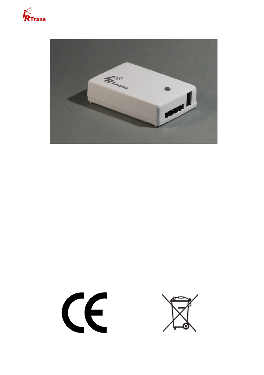
1. IRTrans USB
The IRTrans USB is an infrared (IR) Transceiver with USB PC interface. It can be
supplied with power by the USB connection as well as by an external power
supply.
It offers the following basic functions:
Transmit IR
Receive IR
1 output to connect external IR transmitters
USB interface
IRTrans 2/3 wire bus
RS232 interface
1 status input
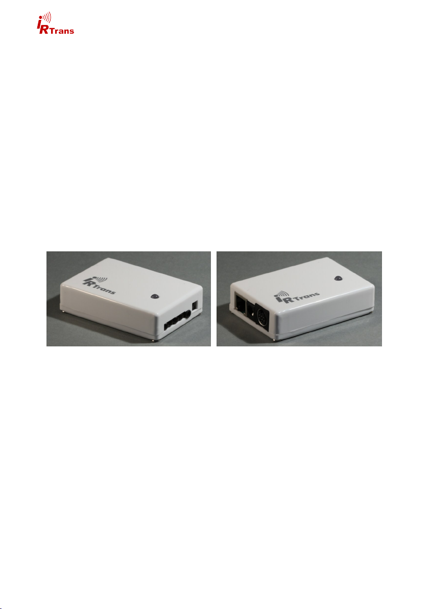
1.1 Connections
IRTrans USB back side
On the back side there are :
USB connector (USB B connector)
Connector for external power supply
MiniDin 8 connector for accesories
On the front side there are 4 IR LEDs next to the IR receiver (ref. picture on page
2).
4
©2012 IRTrans GmbH
Hardware Guide USB - RS232 - Translator - Mediacontroller
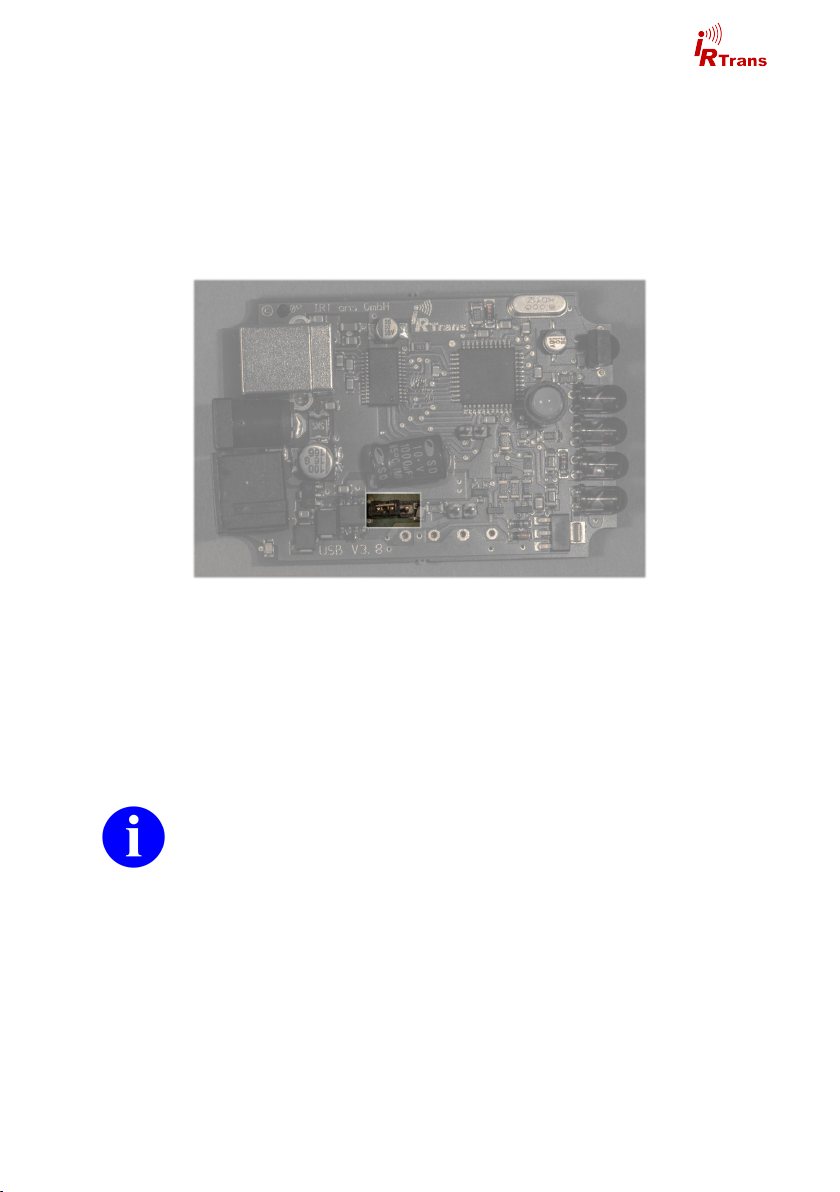
1.2 Power supply
The IRTrans USB can be supplied by the USB connection. If the PC allows for
this the IRTrans USB may be supplied with power during standby as well. This
function is normally deactivated because the USB standard only allows for 0,5mA
during standby. Some mainboards/PCs however have cam be configured to
power USB devices during standy. To do that please refer to your PC documentation. To supply the IRTrans with standby USB power the jumper shown in the
picture must be moved to the right.
Jumper for USB standby power (deactivated position)
For an external power supply there is a 5.5/2.1mm hollow connector. The external power supply should be capable of delivering 8-16V with approximately
100mA per IRTrans Module. The positive lead must be wired to the center termi-
nal.
1.3 USB connection / installing drivers
Before connecting the IRTrans to the PC the software has to be installed.
The IRTrans USB will be connected to the PC by an USB A to B type cable. After
connecting the IRTrans driver installation will start automatically.
Windows 2000 / XP / Server 2003 / Vista / 7
IRTrans USB drivers are digitally signed and included in the IRTrans software
installer (setup.exe). Futhermore the drivers are available from the Microsoft driver database as well.
© 2012 IRTrans GmbH
5

Hardware Guide USB - RS232 - Translator - Mediacontroller
Linux
Linux Kernels 2.6.5/2.4.26 include USB drivers in the standard kernel. The following driver packages have to be activated:
Usbserio
FTDI_serio
USB subsystem
These drivers should be configured as modules. If the USB device daemon is
running the system recognizes the IRTrans upon connection and will install the
correct drivers automatically. There will be entries to the syslog to monitor installation progress. The IRTrans USB will be assigned a device (e.g. /dev/tty/USB0).
The device ID will vary according to your system configuration.
Mac
Drivers for Mac OSX 10.4 or later are available on the IRTrans software CD or
are downloadable from the website http://www.irtrans.de/en/.
6
©2012 IRTrans GmbH

Hardware Guide USB - RS232 - Translator - Mediacontroller
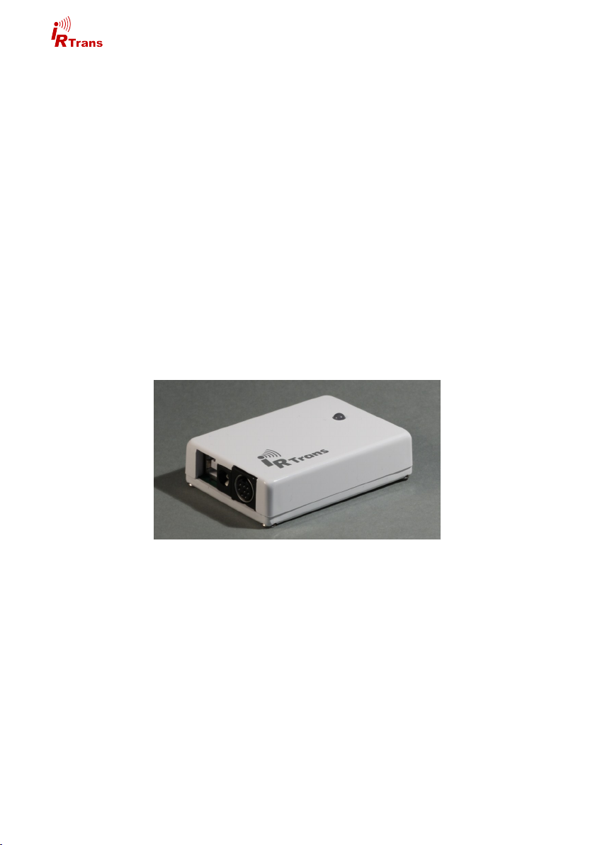
2. IRTrans Translator
The IRTrans Translator is based on an IRTrans USB. An integrated command
database allows to receive, translate and send IR commands independently.
Compared to the IRTrans USB the IRTrans Translator offers the following additional features:
128K IR database (sufficient for approx. 1000-1500 commands)
2 IR receivers
IRTrans Translator front
2.1 Connections
On the front there are left to right:
4 IR LEDs
Status LED
2 IR receivers
On the back you will find:
3,5mm jack for external receivers
MiniDin 8 connector for accessories
USB connector
Connector for external power supply
© 2012 IRTrans GmbH
IRTrans Translator back
7
Hardware Guide USB - RS232 - Translator - Mediacontroller
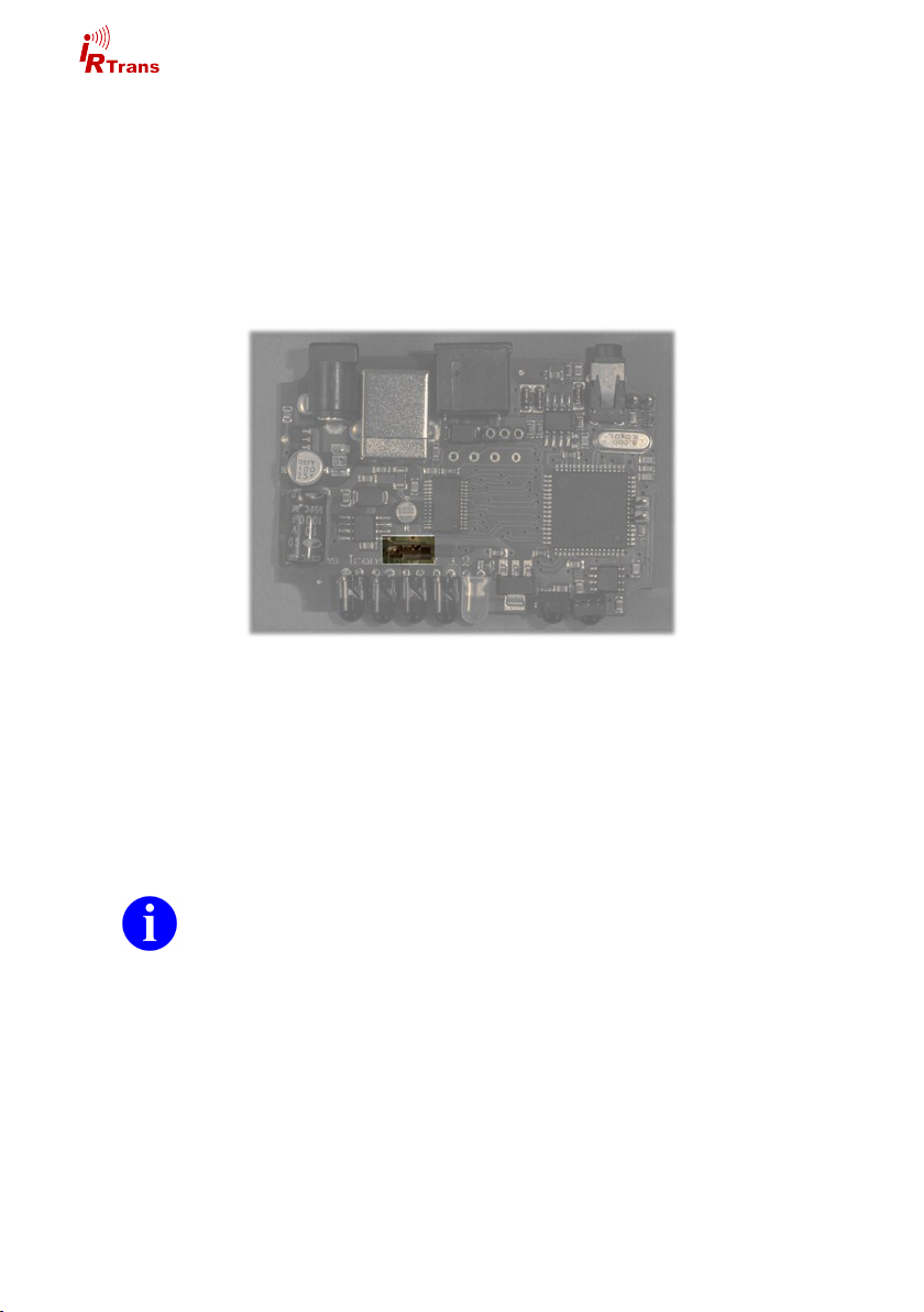
2.2 Power supply
The IRTrans USB can be supplied by the USB connection. If the PC allows for
this the IRTrans USB may be supplied with power during standby as well. This
function is normally deactivated because the USB standard only allows for 0,5mA
during standby. Some mainboards/PCs however have cam be configured to
power USB devices during standy. To do that please refer to your PC documentation. To supply the IRTrans with standby USB power the jumper shown in the
picture must be moved to the left.
Jumper for USB standby power
For an external power supply there is a 5.5/2.1mm hollow connector. The external power supply should be capable of delivering 8-16V with approximately
100mA per IRTrans Module. The positive lead must be wired to the center termi-
nal.
2.3 USB connection / installing drivers
Before connecting the IRTrans to the PC the software has to be installed.
The IRTrans USB will be connected to the PC by an USB A to B type cable. After
connecting the IRTrans driver installation will start automatically.
Windows 2000 / XP / Server 2003 / Vista / 7
IRTrans USB drivers are digitally signed and included in the IRTrans software
installer (setup.exe). Futhermore the drivers are available from the Microsoft driver database as well.
8
©2012 IRTrans GmbH

Hardware Guide USB - RS232 - Translator - Mediacontroller
Linux
Linux Kernels 2.6.5/2.4.26 include USB drivers in the standard kernel. The following driver packages have to be activated:
Usbserio
FTDI_serio
USB subsystem
These drivers should be configured as modules. If the USB device daemon is
running the system recognizes the IRTrans upon connection and will install the
correct drivers automatically. There will be entries to the syslog to monitor installation progress. The IRTrans USB will be assigned a device (e.g. /dev/tty/USB0).
The device ID will vary according to your system configuration.
Mac
Drivers for Mac OSX 10.4 or later are available on the IRTrans software CD or
are downloadable from the website http://www.irtrans.de/en/.
© 2012 IRTrans GmbH
9
Hardware Guide USB - RS232 - Translator - Mediacontroller
3. IRTrans RS232
The IRTrans RS232 is an IR Transceiver with RS232 serial interface.
This are the basic features:
Transmit IR
Receive IR
1 output for external IR transmitter
1 input for external IR receivers
IRTrans 2/3 wire bus
RS232 interface
1 status input
3.1 Connections
IRTrans RS232 front
Left to right:
4 IR LEDs
1 3,5mm jack for external IR
receivers
Internal IR receiver
3.2 Power supply
The IRTrans RS232 is powered through a 5.5/2.1mm hollow connector. The external power supply should be capable of delivering 8-16V with approximately
100mA per IRTrans Module. The positive lead must be wired to the center termi-
nal.
Left to right:
RS232 connector
Power supply connector
MiniDin8 connector for exter-
nal accessories
10
IRTrans RS232 back
©2012 IRTrans GmbH

Hardware Guide USB - RS232 - Translator - Mediacontroller
3.3 RS 232 Schnittstelle
The IRTrans RS232 uses a 6-pin modular jack for the serial sonnection. The cable must be wired like this:
Signal Pin (PC - SubD9) Pin IRTrans
GND 5 5
RTS 7 4
TxD 3 3
CTS 8 2
RxD 2 1
4. IRTrans Mediacontroller
The IRTrans Mediacontroller is an IRTrans RS232 with additional features:
128K IR database (sufficient for approx. 1000-1500 commands)
PowerOn option built in (ref. chapter 5.4)
5. IRTrans Server Software
The IRTrans server application is not specific to the IRTrans device you are using. Its usage is described by the software handbook. This is a short guide for
the first start.
Windows
The setup program copies the entire IRTrans software suite to the hard drive.
There will be corresponding entrires to the start menu.
Linux
In Linux the installation script will copy the irtrans software to /usr/local/irtrans.
Startup of the IRTrans server is to be carried out in a shell.
The IRTrans server software is capable of scanning USB ports for IRTrans devices but when used with RS232 devices the server must be started with the device ID: „irserver /dev/ttyS0“
Automatically searching for USB devices is accomplished with: „irserver usb“.
You may secify a device ID as well when starting the irserver.
© 2012 IRTrans GmbH
11

Hardware Guide USB - RS232 - Translator - Mediacontroller
5. Mini DIN 8 connector for external accessories
There is a Mini-DIN 8 connector to plug external accessories into the IRTrans.
The following options are available:
External IR transmitters
RS232 interface
Status input
IRTrans bus
PowerOn Relay
The pins are assigned as follows:
1: GND
2: +8-16V power
3: Data I/O
4: +5V power
5: PowerOn Relay (1)
6: Output for IR transmitter (anode / +)
7: Output for IR Transmitter (cathode / -)
8: PowerOn Relay (2)
5.1 External IR transmitter
There are a variety of external transmitters available for the IRTrans. They are
connected to pins 6 and 7 of the Mini-DIN connector
5.1.1 stick on minitransmitter
The minitransmitters can be sticked directly to the IR receiver of the your devices.
Please note:
Mini DIN 8 connector
View from the contact
side
12
The transmitter casing is not transparent all the way around. The transmit-
ters will only work when the paper of the sticker is removed.
Range is limited to 20-30cm (~1ft). The transmitters should be sticked
directly to the IR receiver.
Individual control of multiple external transmitters is not possible with the
IRTrans devices covered by this handbook.
Standard cable length is 1,8m (~6ft). Cables may be extendet to up to 5m
(~15ft). Longer cables may cause signal distortions.
Important: When using external high power transmitters there is a jumper
to enable full power. This jumper must be removed when using minitransmitters.
©2012 IRTrans GmbH
Hardware Guide USB - RS232 - Translator - Mediacontroller
5.1.2 external high power IR transmitters
The external high power transmitters are equal to the built in IR LEDs. They are
available in a high frequency version as well (455kHz). The high frequency transmitters can be recognised by clear LEDs. High power transmitters can be
connected to all of the IRTrans devices.
Cables should not be extended beyond standard length (1,8m~6ft). Longer
cables lead to distorted IR signals.
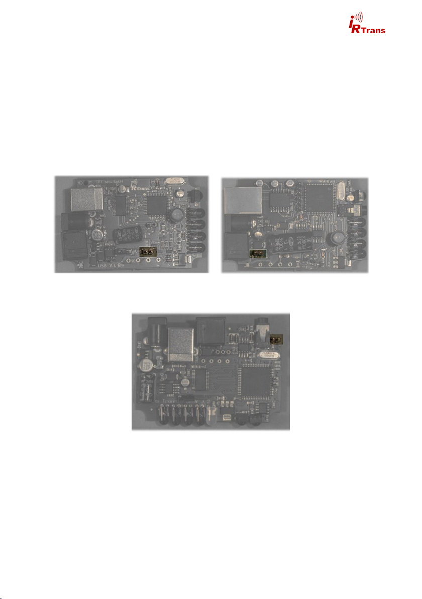
For using external high power transmitters a jumper has to be set inside the IRTrans. The following pictures illustrate the position of this jumper:
The jumper must not be set when using stick on minitransmitters!
IRTRans USB
© 2012 IRTrans GmbH
IRTrans RS232 / Mediacontroller
Translator
13

Hardware Guide USB - RS232 - Translator - Mediacontroller
5.2 Status input
Using the state input the IRTrans can recognise the state of a device and send
different IR codes accordingly. The state input will be configured with the IRTrans
software.
Do not exceed 5,0V on the state input!
5.3 IRTrans bus
The IRTrans 2 wire bus is a serial bus that can be controlled by an IRTrans USB
or RS232. IRTrans bus modules extend IR coverage to multiple rooms and can
be addressed independently through the IRTrans USB / RS232. One bus can be
made up of up to 16 IRTrans devices.
When using the IRTrans bus all connected devices have to be powered
to avoid communication problems.
There are no special requirement to the cables used for the IRTrans bus. Topology is no constraint as well, even tree topologies are possible.
The IRTrans Bus has been tested with cable lengths up to 30m (100ft). Loger
cables may be possible. When connecting different buildings there must galvanic
isolation.
The IRTrans bus uses pins 1 (GND) and 3 (data).
There is the option of using 3 wires and connecting power to the bus modules by
using pin 2 (+8-16V). Do not use pin 4 it is not protected against too high current.
Also long cable runs lead to a drop in voltage which in turn may cause the bus
module not to work correctly.
When using 3 wires only one IRTrans device must be powered by an external
power supply. Powering the entire bus by USB is not possible, an external power
supply has to be used.
Powering the bus should be accomplished by using the hollow connector
of one of the IRTrans modules. This connector is equipped with a fuse to
protect the IRTrans bus.
14
©2012 IRTrans GmbH

Hardware Guide USB - RS232 - Translator - Mediacontroller
5.4 PowerOn relay
IRTrans devices with the PowerOn option have an additional relay to switch on
ATX PCs. The two pin connector of the power on cable has to be connected to
the power on pins of your mainboard. The power on connector of the PC case
can be connected in turn to the power on cable.
This relay is only capable of switching 24V/500mA. Do not use higher
voltages or currents.
© 2012 IRTrans GmbH
15

 Loading...