

Hardware Guide
Ethernet - Ethernet PoE
Version 2013.02

Hardware Guide Ethernet - Ethernet PoE
EG Declaraon of Conformity
The following products
are conrmed to comply with
DIN EN 55024: 1998 + A1: 2001 + A2: 2003.
IRTrans Ethernet / IRDB
IRTrans Ethernet PoE / IRDB / IO
2
©2012 IRTrans GmbH

Hardware Guide Ethernet - Ethernet PoE
Contents
1. IRTrans Ethernet ......................................................................... 4
1.1 Connections ..................................................................................... 4
1.2 Power supply .................................................................................... 5
2. IRTrans Ethernet PoE ................................................................. 6
2.1 Connections ..................................................................................... 6
2.2 Power supply .................................................................................... 7
3. Ethernet interface ....................................................................... 8
4. External transmitters .................................................................. 9
4.1 stick on minitransmitters ................................................................... 9
4.2 external high power transmitters ...................................................... 9
4.3 Devices with 2X option ..................................................................... 10
5. Connecting external IR receivers.............................................. 10
6. RS232 interface ........................................................................... 10
7. Start-Up ........................................................................................ 11
8. Webinterface ............................................................................... 12
9. Reset to factory defaults ............................................................ 15
© 2012 IRTrans GmbH
3

Hardware Guide Ethernet - Ethernet PoE
1. IRTrans Ethernet
The IRTrans Ethernet is an IR Transceiver with network interface.
Basic features are:
Receive an transmit IR
1 output fo external IR transmitter
1 input for external IR receivers
10/100 MBit network interface
Webinterface for configuration
IRTrans devices with the optional IR database offer additionally:
128k IR database (sufficient for approx. 1000-1500 IR commands)
Use withour IRServer
128k flash memory for own html pages
IRTrans devices with the optional 2X option:
2nd independent IR output (stereo jack output)
1.1 Connections
On the back there are:
IRTrans Ethernet back
Ethernet connector
5,5/2,1mm connector for power supply
Output for external IR transmitters
On the front there are 4 IR LEDs, 1 IR receiver and a 3,5mm jack to connect external IR receivers.
4
©2012 IRTrans GmbH

Hardware Guide Ethernet - Ethernet PoE
1.2 Power supply
The IRTrans Ethernet is powered by an external power supply. It must deliver 8-
16V and 300mA per IRTrans device. The positive lead is wired to the center ter-
minal of the 5,5/2,1mm hollow connector.
A 5,5/2,5mm connector may fit as well but will not have reliable contact.
The IRTrans will encounter seemingly inexpliccable reboots.
When using external high power transmitters the power supply should be
capable of delivering 500mA.
© 2012 IRTrans GmbH
5

Hardware Guide Ethernet - Ethernet PoE
2. IRTrans Ethernet PoE
The IRTrans PoE is mostly identical to the IRTrans Ethernet devices. It is available with IR database and 2X option as well.
Differences to the IRTrans Ethernet:
Power supply over Ethernet (PoE). Alternatively an external power supply
may be used.
2x option with own connector
2.1 Connections
IRTrans Ethernet PoE back
On the back there are from left to right:
Ethernet connector
2nd output for external transmitter: 3,5mm jack
1st output for external transmitter: 3,5mm jack
above: connector for external power supply
status LED of the power supply
The left 3,5mm jack is always built into the devices but deactivated without 2X
option.
6
©2012 IRTrans GmbH

Hardware Guide Ethernet - Ethernet PoE
2.2 Power supply
The IRTrans Ethernet PoE may be supplied with power by an IEEE 802.3af conformal Power over Ethernet switch. According IEEE802.3af the power may be
supplied by a free conductor pair as well as by a data pair.
Older switches not conforming to IEEE802.3af may not be usable to power the
IRTrans PoE.
For an external power supply there is a 5.5/2.5mm hollow connector. The external power supply should be capable of delivering 4,5-6V with approximately
300mA. The positive lead must be wired to the center terminal.
If there is power available either via PoE or by external supply the blue
LED next to the power connector will be lit´.
The IRTrans Ethernet PoE requires a different voltage power supply
compared to other IRTrans modules. For this reason the power connector is 5,5/2,5mm.
© 2012 IRTrans GmbH
7

Hardware Guide Ethernet - Ethernet PoE
3. Ethernet interface
The Ethernet interface allows to integrate the IRTrans in any IP based Ethernet.
The IP stack runs on a Freescale MC9S12NE64 processor.
The ethernet interface is configured to use 10MBit/s per default. 100MBit/s is
possible but not recommended due to higher power consumption and more heat
generated inside the IRTrans. The packages used to control the IRTrans are usually not larger than 100 bytes so using 100MBit does not improve performance.
Switching to 100MBit is accomplished by setting a jumper inside the device. The
jumper must short pins 4 and 5 of the 6 pin header.
Position of the 6 pin header
Communication between the IRTrans and the server usually happens on
TCP/UDP port 21000. This port is registered for IRTrans and may have
to be opened in firewalls.
When there is an active link the green LED on the Ethernet connector will light
up. The yellow LED flashes when data is transmitted.
By default the IRTrans uses DHCP to acquire an IP Adress. If there is no DHCP
Server available the device automatically falls back to 192.168.0.32.
8
©2012 IRTrans GmbH

Hardware Guide Ethernet - Ethernet PoE
4. External IR transmitters
There are a variety of external transmitters available with 3,5mm jacks.
4.1 stick on minitransmitters
The minitransmitters can be sticked directly to the IR receiver of the your devices.
Please note:
The transmitter casing is not transparent all the way around. The transmit-
ters will only work when the paper of the sticker is removed.
Range is limited to 20-30cm (~1ft). The transmitters should be sticked
directly to the IR receiver.
Individual control of multiple external transmitters is not possible with the
IRTrans devices covered by this handbook.
Standard cable length is 1,8m (~6ft). Cables may be extendet to up to 5m
(~15ft). Longer cables may cause signal distortions.
Important: When using external high power transmitters there is a jumper
to enable full power. This jumper must be removed when using minitransmitters.
4.2 external high power transmitters
The external high power transmitters are equal to the built in IR LEDs. They are
available in a high frequency version as well (455kHz). The high frequency transmitters can be recognised by clear LEDs. High power transmitters can be
connected to all of the IRTrans devices.
Cables should not be extended beyond standard length (1,8m~6ft). Longer
cables lead to distorted IR signals.
For using external high power transmitters a jumper has to be set inside the IRTrans. The following pictures illustrate the position of this jumper:
The jumper must not be set when using stick on minitransmitters!
IRTrans Ethernet
© 2012 IRTrans GmbH
IRTrans Ethernet PoE
9

Hardware Guide Ethernet - Ethernet PoE
4.3 Devices with 2X option
IRTrans modules with 2X option offer a second independent output for external
transmitters. The IRTrans PoE is equipped with a second 3,5mm jack for this
purpose. The IRTrans Ethernet uses a stereo plug for the second output.
5. Connecting external IR receivers
External receivers can be connected by a 3,5mm jack next to the built in IR receiver.
When using an external receiver it must be enabled in the device settings and the
correct receiver type has to be selected.
Older IRTrans Ethernet modules (up to hardware revision 2.2) cannot select the
receiver by software. When using an external receiver with this devices a jumper
has to be set inside the IRTrans. This jumper is located behind the built in receiver and will disable the internal receiver thus enabling the external input. This is
not necessary with current revision or PoE devices.
When using external receivers firstly the receiver must be enabled and
secondly the correct receiver type has to be selected with the IRTrans
software.
6. RS232 interface
Instead of connecting an external IR receiver the connector may be used as a
serial communication port. To use this a special active RS232 cable is required
and the connection can only be uni directional.
10
©2012 IRTrans GmbH

Hardware Guide Ethernet - Ethernet PoE
7. Start-Up
For configuring the IRTrans Ethernet / PoE there is a password. By default
(factory settings) this password is:
user: admin
password: irtrans
The password may be changed in the user interface.
The IRTrans Ethernet / PoE devices ship with DHCP enabled. Hence the IRTrans
searches for a DHCP Server and requests an IP adress with its MAC. The MAC
adress is printed on the label.
If there is no DHCP server or the server does not assign an IP adress to
the IRTrans the device will fall back to the IP adress 192.168.0.32.
Included in the IRTrans software suite is the tool „IPAssign“. It is available both
as GUI (Windows) and as console (Windows & Linux). Using IPAssign it is possible to modify the IRTrans IP settings. IPAssign „mimics“ a DHCP server for this
purpose therefore the DHCP ports must not be blocked by a firewall.
IPAssign searches the network for IRTrans devices and sorts them according to
MAC adresses. An entry marked with „DHCP“ means that this device obtained ist
settings from a DHCP server. After selecting an IRTrans device its settings can
be changed. Writing the settings to the device („Set IP“) requires the correct device password to be entered
Now knowing the IP adress of the IRTrans the IRTrans server can be started.
Additional settings can be modified by the IRTrans servers „device status“ dialogue or the devices web interface.
© 2012 IRTrans GmbH
11

Hardware Guide Ethernet - Ethernet PoE
8. Webinterface
IRTrans devices with Ethernet offer a browser based configuration interface. All
parameters that can be altered by the web interface can be accessed by the IRTrans servers device status dialogue as well.
To access the web interface simply type the IP adress of the IRTrans in an internet browser:
http://192.168.0.32
The adress will chance according to your network settings.
You will now see the Login page:
IRTrans Webinterface - Login
The password may be changed by selecting „Change Password“. Although access to the IR functions of the IRTrans may be restricted using access rights
(refer to software handbook) the webinterface is always reachable from the sub-
net where the IRTrans is located.
All options accessible through the webinterface are identical to the corresponding
options of the device status. For a detailed description refer to the software handbook.
12
©2012 IRTrans GmbH

Hardware Guide Ethernet - Ethernet PoE
The IP Settings dialog to configure
the IP parameter. The following fields
are defined:
Use DHCP: Activates the automatic
IP assignment via DHCP.
Fallback …: When no DHCP server
is available the device falls back to
the default address 192.168.0.32
after 30s.
IP Address: Manually configured IP
address
Subnet mask: Manually configured
IP subnet mask
Default Gateway: Manually configured default gateway
In the lower lines the currently active parameters including the MAC address are
displayed.
The button „Store Configuration“ transfers all values to the non-volatile EEPROM
of the device.
The Access Rights dialog configures the access rights of the device. If no values
are entered here, any client can access the device. As soon as at least one value
is entered only clients that fit into at least one of the entries are allowed to access
the device.
Each entry consists of an IP address
and a subnet mask: 192.168.0.0 /
255.255.255.0 enables all clients
within the network 192.168.0.x. An
entry 192.168.0.1 / 255.255.255.255
allows only one client to use the
IRTrans LAN. The access rights are
active for all TCP and UDP functions.
To avoid a complete lock-out it is always possible to access the web front end
from within the local network of the device – even if there is no entry for that subnet.
© 2012 IRTrans GmbH
13

Hardware Guide Ethernet - Ethernet PoE
The IR Relay configuration is used to configure the relaying of IR signals from
one IRTrans Ethernet to another. In general IR signals received by other IRTrans
Ethernet modules will be relayed automatically. This relaying works without a
server – even with IRTrans devices without an integrated IR database. The exact
configuration of the relaying is done in this dialog.
In the list below “Accept IR Relay
from“ all IRTrans IP Addresses can
be entered from which IR relaying
should be enabled. If the list is empty, all signals will be relayed.
The list below “Send IR Relay to“ tells
the system to which devices received
IR codes should be relayed. Normally
it is enough to enable the checkbox
„Broadcast IR Relay“. Only if IR data
should be relayed to routed networks
it is important to enter a target address because broadcasts will not be
routed. The IR receiving of the irserver is also done via that broadcasts.
That means either broadcast has to
be enabled or the address of the host
running the irserver has to be in this
list – otherwise the irserver will not receive IR codes from this IRTrans module.
The UDP Broadcast fields are only used for modules with integrated IR Database. They define to which address and port formatted IR receive data has to be
sent. The precise format of these telegrams is configured via the IR database.
The IR parameters can either be configured using the IRTrans GUI client or
via the webpage “IR Configuration”.
All the fields and their meanings are
explained in detail in the Users manual
for the IRTrans system.
Of course both ways of configuration
can be used alternately.
14
©2012 IRTrans GmbH
Hardware Guide Ethernet - Ethernet PoE
9. Reset to factory defaults
If it should become neccessary to reset the IRTrans to factory defaults (e.g. the
password has been lost) this can be accomplished as follows:
Remove power from the device and open the case.
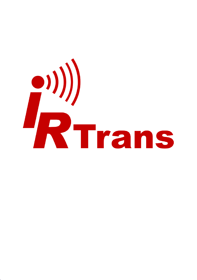
Resetting the IRTrans will be done by shorting pins 5-6 of the 6 pin header inside
the device:
6-pin header
After putting a jumper on pins 5 and 6 power up the device and wait a few seconds. The status LED will flash green-red once. Now remove power again and
remove the jumper. The IRTrans is reset to factory defaults.
© 2012 IRTrans GmbH
15

 Loading...