

Page 1

3006-dva.ib.doc Page 1 of 8 26.02.2003
IRT Eurocard Types
DVA-3006
270 Mb/s ASI/SDI 8 O/P
Distribution Amplifier
Designed and manufactured in Australia
IRT can be found on the Internet at:
http://www.irtelectronics.com
I R T Electronics Pty Ltd A.B.N. 35 000 832 575
26 Hotham Parade, ARTARMON N.S.W. 2064 AUSTRALIA
National: Phone: (02) 9439 3744 Fax: ( 02) 9439 7439
International: +61 2 9439 3744 +61 2 9439 7439
Email: sales@irtelectronics.com
Web: www.irtelectronics.com
IRT Communications
www.irtcommunications.com
Page 2

3006-dva.ib.doc Page 2 of 8 26.02.2003
DVA-3006
270 Mb/s ASI/SDI 8 O/P
Distribution Amplifier
Instruction Manual
Table of Contents
Section Page
Operational Safety 2
General Description 3
Specifications 4
Technical description 5
Installation 5
Front and rear layouts 6
Maintenance & Storage 7
Warranty and service 7
Equipment return 7
Drawing list index 8
This instruction manual applies to units later than S/N 0303051
Operational Safety:
WARNING
Operation of electronic equipment involves the use of voltages and currents that
may be dangerous to human life. Note that under certain conditions dangerous
potentials may exist in some circuits when power controls are in the OFF position.
Maintenance personnel should observe all safety regulations.
Do not make any adjustments inside equipment with power ON unless proper
precautions are observed. All internal adjustments should only be made by suitably
qualified personnel. All operational adjustments are available externally without
the need for removing covers or use of extender cards.
IRT Communications
www.irtcommunications.com
Page 3

3006-dva.ib.doc Page 3 of 8 26.02.2003
General Description
The DVA-3006 270 Mb/s serial digital video distribution amplifier provides the user with a single standard
module to cover a wide range of distribution and monitoring functions for ASI or SDI signals.
Due to the fact that standard loop through techniques used in the analogue domain are unsuitable to the digital
domain most digital equipment comes with no facility to route the input signal to other locations.
As a result a DA is required at almost every point in the digital chain.
Serial digital signals also suffer severe deterioration over relatively short cable distances. The DVA-3006 provides
a means of extending the working distances that can be achieved by equalising and re-transmitting the data in mid
route.
The DVA-3006 may also be used to provide input equalisation for devices not having this feature, as most
unequalised inputs will only support cable lengths of less than 20 metres.
Frequent re-clocking of serial digital signals can lead to serious increases in jitter with resultant data errors. The
DVA-3006 does not include re-clocking so as to minimise these errors, leaving re-clocking to be done by the
receiving device. For applications requiring reclocking the DVA-3007 should be used.
An optional rear assembly, ZVA-3006RL (sold separately), provides a bypass relay to switch the Input (SK1) to
Output 1 (SK2) in the event of a power failure. When this bypass rear assembly is used, number of outputs is
reduced to 6.
The DVA-3006 may be mounted in IRT’s 1 RU or 3 RU frames with other analogue or digital modules.
Standard Features:
• For use as buffer or distribution amplifier.
• 8 x in phase 270 Mb/s ASI or 143, 177, 270, 360 Mb/s SDI non reclocked outputs.
• Automatic input equalisation to 250 metres.
• Front panel monitoring output, signal presence LED and external alarm contacts.
• Non reclocking design ideal for use in conjunction with reclocking DA to provide
additional outputs.
O/P 2
O/P 3
O/P 4
O/P 5
O/P 6
O/P 7
O/P 8
OUTPUTS
EQUALISER
SIGNAL FAIL
DETECTION
INPUT
Relay RL 1 = Output Alarm
LINK
ALARM O /P
RL 1
BLOCK DIAGRAM DVA-3006 SIGNAL PATH
O/P 1
MON O/P
(Optional ZDA-3006RL Bypass Rear
Assembly)
(Number of outputs reduced to 6)
RL1
IRT Communications
www.irtcommunications.com
Page 4

3006-dva.ib.doc Page 4 of 8 26.02.2003
Technical specifications
DVA-3006
Input:
Number 1.
Impedance 75 Ohm.
Return loss >20 dB 5 MHz to 270 MHz.
(>15 dB with optional ZVA-3006RL bypass
rear assembly)
Equalisation Automatic better than 250 metres at
270 Mb/s for Belden 8281 or equivalent cable
(reduces to 200m when LK2 is closed).
Outputs:
Number 8 ASI or SDI plus one front panel monitoring output.
Signal level 800 mV ± 10%
Impedance 75 Ohm.
Return loss >20 dB 5 MHz to 270 MHz.
(>15 dB with optional ZVA-3006RL bypass
rear assembly)
DC offset Nil.
Performance:
Output rise time <1 ns, (700 ps typically).
Residual Jitter <0.1 UI (measured with up to 300m of Belden 8281 or
equivalent cable)
Connectors:
BNC.
Indicators:
Power LED (green) for +5v.
Signal present LED (green) when valid ASI/SDI signal present.
Power requirement:
Voltage 28 Vac CT (14-0-14 Vac) or ±16 Vdc.
Consumption 2.0 VA (including ZVA-3006RL optional rear assembly).
General:
Temperature range 0 - 50° C ambient
Mechanical Suitable for mounting in IRT 19" 1RU and 3RU rack
chassis
Size 6 HP x 3U Extended Eurocard (220 mm x 100 mm).
Weight With rear assembly 340g.
Finish:
Front panel Grey background, black lettering & red IRT logo.
Rear assembly Detachable silk screened PCB with direct mount
connectors to Eurocard and external signals.
Standard accessories: Rear connector assembly (supplied with module).
Optional accessories ZVA-3006RL relay bypass rear assembly (6 O/P).
Due to our policy of continuing development, these specifications are subject to change without notice.
IRT Communications
www.irtcommunications.com
Page 5

3006-dva.ib.doc Page 5 of 8 26.02.2003
Technical Description
The input circuit of the DVA-3006 consists of an adaptive cable equaliser IC, which automatically adapts to
equalise any cable length from zero metres to lengths that attenuate the signal by 40 dB at 200 MHz. This
corresponds to 300 metres of Belden 8281 cable. When link LK2 is closed equalisation is reduced to 200 metres for
use in noisy environments or when a short input cable is used. A carrier detect and output mute circuit is used to
mute the output when no signal is present. The DVA-3006 is insensitive to the pathological patterns that can be
present in the serial digital video signal.
The DVA-3006 also features an OUTPUT MONITOR point on the front panel. The output monitor is a isolated
copy of the signal present at the rear panel outputs.
The output of the input stage is coupled to cable driver circuits to provide the eight isolated in phase outputs from
the DVA-3006.
The input cable equaliser circuit U1 incorporates a carrier detection circuit to mute the output when no signal is
applied to the unit. The carrier detect signal energises a relay, RL1 via a transistor, Q1, when carrier is present.
The relay contacts are connected to SK10 on the rear panel to give a failure alarm in the form of a make (or break)
to ground on failure as set by a link LK1, on the circuit board.
The dual AC inputs are rectified and then regulated by a switch mode regulator circuit to provide the +5V
operating voltage for the unit.
+5Vdc is fed to pin 32a of the rear Euro-connector via a polyfuse, JP2. The +5V is to provide power for a signal
bypass relay on the optional ZVA-3006RL bypass rear assembly, should one be used. The polyfuse protects the
+5V power rail by going high impedance should pin 32a be shorted to ground. This protects against the accidental
insertion of the DVA-3006 in anything other than its standard rear assembly or the optional ZVA-3006RL rear
assembly.
Installation
Handling:
The DVA-3006 contains static sensitive devices and proper static free handling precautions should be observed.
When individual modules are stored, they should be placed in antistatic bags and proper antistatic procedures
should be followed when inserting and removing cards from these bags.
Power:
Ensure that the voltage selection of the IRT mounting frame used to house the DVA-3006 and the local AC mains
supply voltage match and that the correct rating fuse is installed in the mounting frame power supply.
Earthing:
Chassis earth connection of the equipment mounting frame is via the earth connection on the three pin (IEC) AC
mains supply inlet. This is a safety earth and must be connected.
Installation in frame or chassis:
See details in separate manual for selected frame type.
LK1 is factory set for a contact make to ground on signal failure at SK10 pin 2 on the rear panel, move LK1 from
the normally closed (N/C) to the normally open (N/O) position for a break to ground on signal or power loss.
Link LK2 closed reduces the input equalisation to 200m for use in noisy environments or when short input cable is
used.
The presence of signal is indicated by the ‘SIGNAL PRESENT’ front panel LED (green).
The presence of the internal +5 Vdc supply is indicated by the front panel LED (green).
It is recommended that unused outputs on the rear panel be terminated with 75 ohm termination plugs.
IRT Communications
www.irtcommunications.com
Page 6
3006-dva.ib.doc Page 6 of 8 26.02.2003
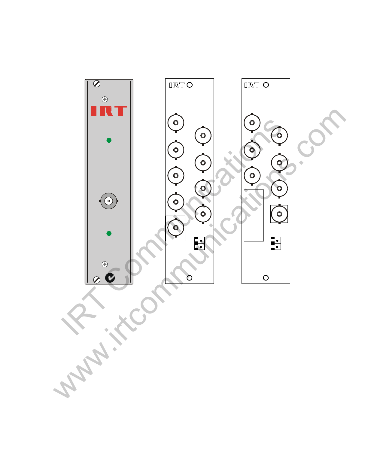
Front & rear panel connector diagrams
The following front panel and rear assembly drawings are not to scale and are intended to show connection order
and approximate layout only.
Note that the ZVA-3006RL is an optional relay bypass rear assembly (sold separately), which bypasses the input
direct to output 1 in the event of a power failure. This optional rear assembly is only compatible with both the
DVA-3006 and DVA-3007 ASI distribution amplifiers and not the previous ASI/SDI distribution amplifiers,
DVA-3001 to DVA-3005.
A
B
C
B
A
SIGNAL
PRESENT
OUTPUT MON
DC
DVA-3006
N140
SK1
2
1
SK10 2 = Alarm
SK10 1 = Gnd
OUTPUTS
SK2
SK8
SK6
SK4
SK9
SK7
SK5
SK3
OUTPUTS
INPUT
SK10
8 O/P ASI/SDI D.A.
RL1R
2
1
SK10 2 = Alarm
SK10 1 = Gnd
SK1
SK6
SK4
SK3
SK7
SK5
SK2
OUTPUTS
INPUT
SK10
6 O/P ASI/SDI D.A
POWER OFF BY PASS SK1-SK2.
ZVA-3006RL
Optional bypass relay
rear assembly
IRT Communications
www.irtcommunications.com
Page 7

3006-dva.ib.doc Page 7 of 8 26.02.2003
Maintenance & storage
Maintenance:
No regular maintenance is required.
Care however should be taken to ensure that all connectors are kept clean and free from contamination of any kind.
This is especially important in fibre optic equipment where cleanliness of optical connections is critical to
performance.
Storage:
If the equipment is not to be used for an extended period, it is recommended the whole unit be placed in a sealed
plastic bag to prevent dust contamination. In areas of high humidity a suitably sized bag of silica gel should be
included to deter corrosion.
Where individual circuit cards are stored, they should be placed in antistatic bags. Proper antistatic procedures
should be followed when inserting or removing cards from these bags.
Warranty & service
Equipment is covered by a limited warranty period of three years from date of first delivery unless contrary
conditions apply under a particular contract of supply. For situations when “No Fault Found” for repairs, a
minimum charge of $A100.00 will apply, whether the equipment is within the warranty period or not.
Equipment warranty is limited to faults attributable to defects in original design or manufacture. Warranty on
components shall be extended by IRT only to the extent obtainable from the component supplier.
Equipment return:
Before arranging service ensure that the fault is in the unit to be serviced and not in associated equipment. If
possible, confirm this by substitution.
Before returning equipment contact should be made with IRT or your local agent to determine whether the
equipment can be serviced in the field or should be returned for repair.
The equipment should be properly packed for return observing antistatic procedures.
The following information should accompany the unit to be returned:
1. A fault report should be included indicating the nature of the fault
2. The operating conditions under which the fault initially occurred.
3. Any additional information which may be of assistance in fault location and remedy.
4. A contact name and telephone and fax numbers.
5. Details of payment method for items not covered by warranty.
6. Full return address.
7. For situations when “No Fault Found” for repairs, a minimum charge of $A100.00 will apply, whether
the equipment is within the warranty period or not.
Please note that all freight charges are the responsibility of the customer.
The equipment should be returned to the agent who originally supplied the equipment or, where this is not
possible, to IRT direct as follows.
Equipment Service
IRT Electronics Pty Ltd
26 Hotham Parade
ARTARMON
N.S.W. 2064
AUSTRALIA
Phone: 61 2 9439 3744 Fax: 61 2 9439 7439
Email: service@irtelectronics.com
IRT Communications
www.irtcommunications.com
Page 8

3006-dva.ib.doc Page 8 of 8 26.02.2003
Drawing List Index
Drawing # Sheet # Description
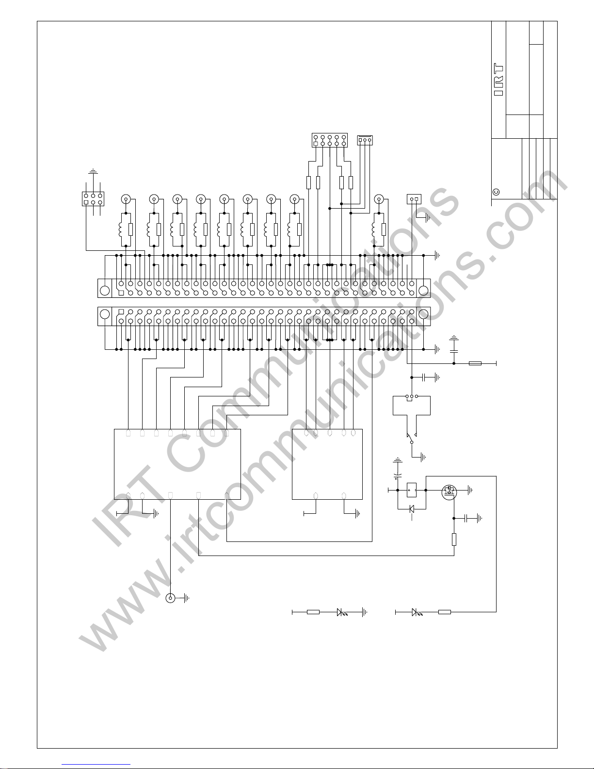
804500 1 DVA-3006 SDI/ASI Distribution Amplifier.
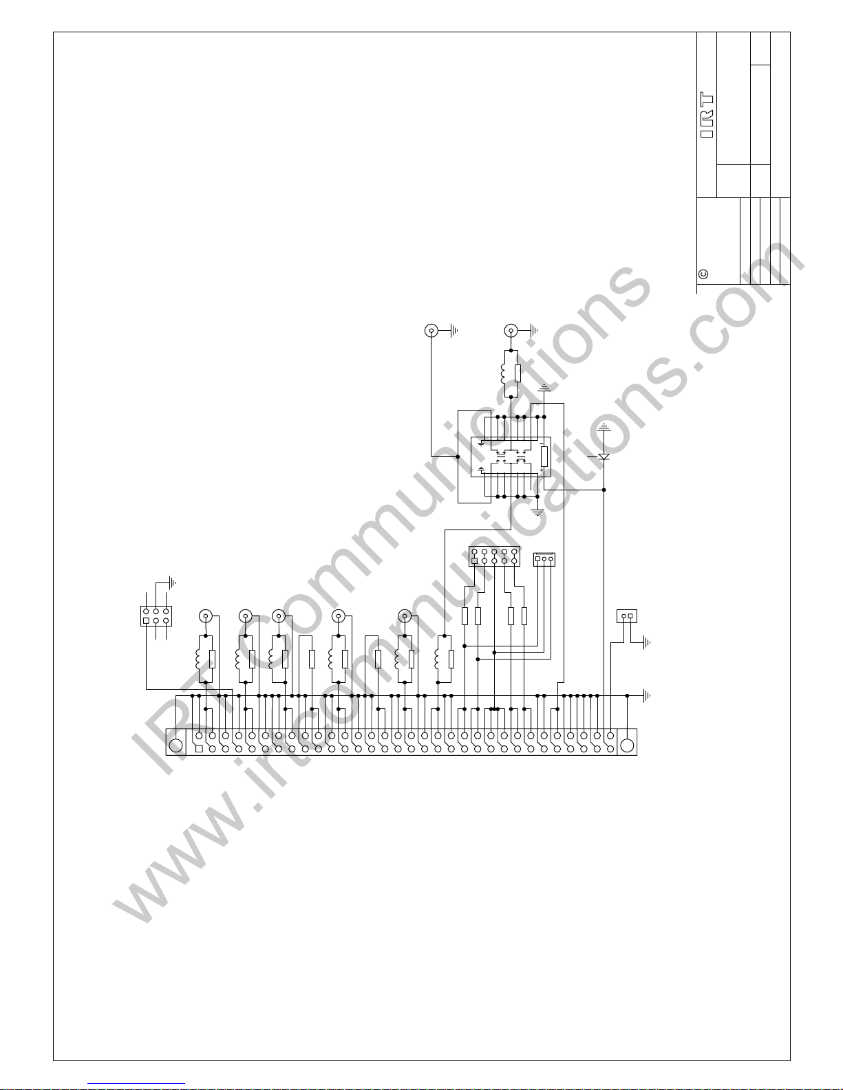
804673 ZVA-3006RL Bypass Relay rear assembly (optional).
IRT Communications
www.irtcommunications.com
Page 9
Title
SCALE
SIZE
Sheet
DRAWN
CHECKED
ENG. APP.
Revision:
DO NOT COPY NOR
DISCLOSE TO ANY
THIRD PARTY
WITHOUT WRITTEN
CONSENT
of1
IRT Electronics Pty. Ltd.
Drawing No.
COPYRIGHT
ARTARMON NSW AUSTRALIA 2064
A3
N.T.S.
1
DVA-3006
804500
Date:
3
26-Feb-2003
SDI/ASI Distribution Amplifier
K.N.
Input
Output 8
Output 7
Output 1
Output 6
Output 2
Output 5
Output 4
Output 3Carrier Detect
+5V
GND
Monitor O/P
Input Equaliser and Output Drivers
I/O
J2 optional power in
(used when fitted to FRU-1030 frame)
AC 1
AC 4
AC 2
AC 3
AC CT
+5V
GND
Power Supply Circuit
PSU
3 1
2
LK1
'DC'
'grn'
21
R36
680R
+5V
n.c.
n.o.
1A1B2A2B3A3B4A4B5A6A6B7A7B8A8B
10A
10B5B11A
11B
12A
12B
13A
13B
14A
15A
15B
17A
17B
18A
18B
9A
9B
20A
20B
14B
21A
21B
22A
22B
23A
24B
24A
25B
26A
27A
27B
28A
23B
19A
19B
30A
30B
26B
31A
31B
32A
32B
25A
16A
16B
28B
29A
29B
P1
DIN64RA
1A1B2A2B3A3B4A4B5A6A6B7A7B8A8B
10A
10B5B11A
11B
12A
12B
13A
13B
14A
15A
15B
17A
17B
18A
18B
9A
9B
20A
20B
14B
21A
21B
22A
22B
23A
24B
24A
25B
26A
27A
27B
28A
23B
19A
19B
30A
30B
26B
31A
31B
32A
32B
25A
16A
16B
28B
29A
29B
J1
DIN64
21
LD1
HLMP-1503
1 25-03-02
PCB 804501
OUTPUTS
1 2
L9R
1 2
L8R
1 2
L7R
1 2
L6R
1 2
L5R
1 2
L4R
1 2
L3R
1 2
L2R
1 2
L1R
INPUT
21
R6
10K
1 2
C11
100nF
+5V
+5V
+5V
MON. O/P
SK11
'SIGNAL'
'grn'
21
R35
680R
21
LD2
HLMP-1503
+5V
ALARM CIRCUIT
CONTACT CLOSURE (OR BREAK)
TO GROUND ON ALARM, AS SET BY LK1
21
R9R21R8R
21
R5R
21
R6R
21
R7R
21
R4R21R3R21R2R
21
R1R
32
1
Q1
BSS123
1 2
C33
4u7
SK1
SK2
SK3
SK4
SK5
SK6
SK7
SK8
SK9
R1R-R9R = 68R
L1R-L9R = 15nH
38
RL1A
V23026
10
1
5
RL1B
2
1
SK10
123
J2
2 1
JP2 0R0
2 1
JP3 0R0
2 1
JP4 0R0
2 1
JP5 0R0
+5V
1 2
JP2
RXE020
POLYFUSE
2 14-11-02 ECR1411
1 3
2
D2
BAS16
12
C39
10nF
1 2
C40
10nF
3 10-01-03 ECR1439
13579
P2
1 2
3 4
5 6
P3
IRT Communications
www.irtcommunications.com
Page 10
Title
SCALE
SIZE
Sheet
DRAWN
CHECKED
ENG. APP.
Revision:
DO NOT COPY NOR
DISCLOSE TO ANY
THIRD PARTY
WITHOUT WRITTEN
CONSENT
of1
IRT Electronics Pty. Ltd.
Drawing No.
COPYRIGHT
ARTARMON NSW AUSTRALIA 2064
A3
N.T.S.
1
ZVA-3006RL
804673
Date:
1
14-Nov-2002
SDI/ASI D.A. Rear Panel
K.N.
1 11-07-02
PCB 804674
R2R-R7R = 220R
L2R-L7R = 18nH
J2 optional power in
(used when fitted to FRU-1030 frame)
1A1B2A2B3A3B4A4B5A6A6B7A7B8A8B
10A
10B5B11A
11B
12A
12B
13A
13B
14A
15A
15B
17A
17B
18A
18B
9A
9B
20A
20B
14B
21A
21B
22A
22B
23A
24B
24A
25B
26A
27A
27B
28A
23B
19A
19B
30A
30B
26B
31A
31B
32A
32B
25A
16A
16B
28B
29A
29B
J1
DIN64
OUTPUTS
1 2
L7R
1 2
L6R
1 2
L5R
1 2
L4R
1 2
L3R
1 2
L2R
1 2
L1R 18nH
INPUT
21
R7R
21
R6R
21
R4R
21
R5R
21
R3R
21
R2R
21
R1R 56R
SK1
SK2
SK3
SK4
SK5
SK6
SK7
2
1
SK10
123
J2
2 1
JP2 0R0
2 1
JP3 0R0
2 1
JP4 0R0
2 1
JP5 0R0
123456789
1013
141516171819202122
RL1R
G5Y-254P
13
2
D1R BAS16
2 1
R8R
75R
2 1
R9R
75R
2 11-11-02 ECR1415
1 2
3 4
5 6
P3
MTMM-103
13579
P2
MTMM-105
IRT Communications
www.irtcommunications.com
 Loading...