

Page 1
OVERVIEW & OPERATION
The LDT-700 series is a 2-pole dual technology line voltage
wall switch sensor designed to fit in a standard NEMA wall
box for automatic lighting control. This state-of-the-art wall
switch sensor combines digital Passive Infrared and
advanced High Frequency Dopplersensing technologies into
an aesthetically pleasing housing to provide excellent
occupancy/vacancy sensing performance within its 180° field
of view detection range.
The LDT-700 contains two relays and two push buttons, for
controlling two lighting loads independently. A dual color LED
indicates the sensor detection, BLUE for PIR and GREEN for
HFD. Pressing the push-button will change the state of relay
contacts manually. The sensor provides typical occupancy
sensing (Auto-ON, Auto-OFF) control on pole-1 and vacancy
sensing (Manual-ON, Auto-OFF) control on pole-2. Different
control modes of each pole can be programmed via DIP
switch settings. Presentation Mode (PM) allows the occupant
to switch OFF the load as desired by pressing the specific
push-button. The load will remain OFF if motion is detected
before the time delay elapses. Pressing the push-button
again will turn the load back ON and the sensor will operate
as per sensor setting. If no motion has been detected and the
time delay expires, sensor will return to normal operation and
turn ON the load with the next sensed motion.
INSTALLATION NOTES
SPECIFICATIONS
Line Voltage Dual-Tech Wall Switch Sensor
INSTALLATION INSTRUCTIONS
LDT-700 series
Power supply
Sensing technology
Inrush current
Load switching
Detectable speed
Mounting height
Ambient light level
Delay time setting
Op. humidity
Op. temperature
Dimensions
Detection coverage
Maximum load,
per pole
120/277VAC, 60Hz
Digital PIR & High Frequency Doppler
Incandescent/Halogen – 800W (VA)
Fluorescent Ballast/CFL – 800W (VA)
Ballast Electronic (LED) – 500/800VA@120/277V
Motor – 1/6 HP
Max. 80A,
16.7 ms @60Hz, per pole
Zero-cross Hybrid-Switching
1~10 ft./sec. (0.3~3 m/sec)
3~5 ft. (90~150 cm) above the floor
Major motion - 30 ft x 40 ft (W x L) @4 ft high
Minor motion - 20 ft x 20 ft (W x L) @4 ft high
7 levels, from dark to 24 Hour
T/1’/3’/5’/10’/20’/30’, T=10 sec. for testing
Max. 95% RH, non-condensate
-40°F ~ 131°F (-40°C ~ 55°C)
4.13”H x 1.77”W x 1.65”D (w/mounting plate)
INDOOR USE ONLY
Utilisation a L'interieur Uniquement
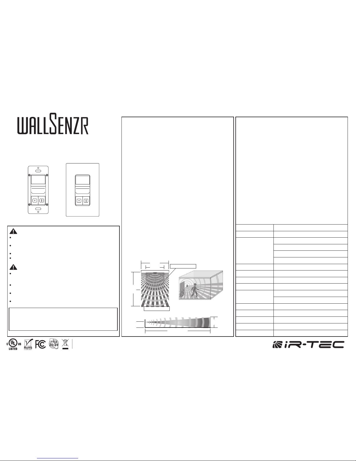
DETECTION COVERAGE
40’
Top view
Side view
4’
7’
30’
40’
Minor motion
20’
20’
Major motion
180°, 30 ft x 40 ft (W x L)
Risk of Electric Shock - Disconnect power supply at the circuit breaker
before installing, replacing lamps, or servicing.
DO NOT control a load in excess of specified ratings to avoid damaging the
sensor or the property.
Install and use this sensor in accordance with electrical codes and regulations.
This device is intended to be installed by a qualified electrician. DO NOT
attempt to service or repair.
Afin d'eviter tout risque de choc electrique ou electrocution, couper le
courant au disjoncteur avant installation, remplacement des lampes ou
tout service d'entretien.
NE PAS contrôler une charge supérieure à la capacité spécifiée pour éviter
d'endommager le capteur ou la propriété.
Installer et utiliser ce capteur conformément aux codes et règlements
électriques.
Ce dispositif est destiné à être installé par un électricien qualifié. NE PAS
tenter de réparer.
This device complies with Part 15 of the FCC Rules.
Operation is subject to the following two conditions:
(1)This device may not cause harmful interference,
(2)This device must accept any interference received,
Including interference that may cause undesired operation.
FCC NOTICE
WARNING & CAUTION
AVERTISSEMENT & PRUDENCE
Install the sensor at least 1ft. away from any occupant.
The sensor is more sensitive to the movements
“crossing” the detection zones than “toward” or “away”
the sensor. To obtain better sensitivity, ensure the sensor
to have clear field of view for the occupant’s motion
within the desired coverage.
The closer movement is to the sensor, the more
sensitive the sensor is.
The sensor should be mounted within the specified
mounting height for optimal performance.
Avoid blocking the sensor with any obstacles, such as
door, plant, partition or furniture. As a general rule, every
occupant within the desired range should be able to
clearly see the sensor.
Do NOT mount the sensor directly above or nearby a
heat source, or where unintended motion (e.g. hallway
traffic) will be “seen” by the sensor.
1.
2.
3.
4.
5.
P/N: 058-70005-004 Printed in Taiwanwww.irtec.com
This product may be covered by one or more U.S. patents or patent applications.
Please visit www.irtec.com for more information.
Page 2
INSTALLATION
Ensure the power has been turned OFF at the circuit
breaker.
Prepare the wires with proper length (cut the excessive
length, if necessary) and strip for connection. Connect
the sensor wires to the wires of line voltage and load
according to the wiring diagram of desired control.
Carefully bend the wires in the wall box after all wires are
properly connected. Mount the sensor in the wall box
with the screws provided.
Conduct sensor operation test (refer to the TESTING
section). Replace the wall plate cover after sensor
testing and setting completed.
1.
2.
3.
4.
WIRING DIAGRAM
The sensor may be available with other control options,
consult a qualified engineer or contact info@irtec.com for
assistance.
Dual Circuit Control
Bi-Level Control
Sensor
Red
Brown
White
Black
Blue
Line
Green
Ground
Neutral
Primary
Load
Secondary
Load
Line
120/277VAC
Sensor
Red
Brown
Black
Blue
Line 1
Line 2
Green
Ground
Neutral
Line
120/277VAC
Primary
Load
Secondary
Load
White
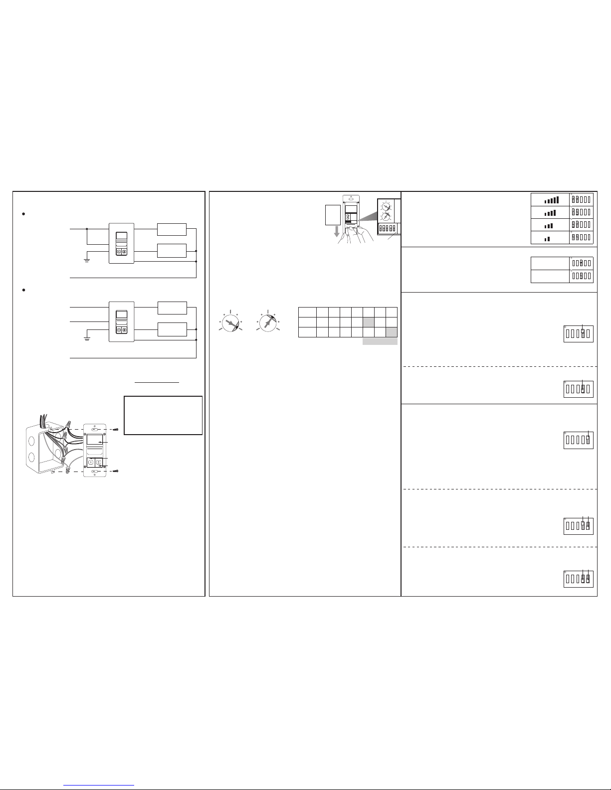
TIME setting determines the delay time that the sensor will
hold the load ON after the last motion detected. Factory
setting is 10 minutes, and it can be changed by pointing
the arrowhead of potentiometer to the specific position.
TIME - Delay time
LUX setting determines the threshold of ambient light level
that the sensor will inhibit switching on the load. The factory
setting is ALS disabled (24 Hr) for testing convenience,
and it can be changed by pointing the arrowhead of
potentiometer to the specific position.
LUX – Ambient light level
TESTING
Restore the line power for sensor operation and wait for
the sensor to warm-up (GREEN LED will blink during the
warm-up period).
Move within the desired range and observe the sensor
detection. BLUE blink indicates the PIR sensor detected,
and GREEN blink indicates the HFD sensor detected.
Move outside of the desired range and observe if the
HFD sensor can detect. If GREEN LED blinks, reducing
the HFD sensitivity accordingly.
Replace the wall plate cover after sensor testing and
setting completed.
1.
2.
3.
NOTE: The connected load will be switched ON as delay
time set (factory default 10 minutes) after the power applied.
The delay time can be set to the shortest (10 seconds) for
test convenience. Ensure to set the TIME back to the
desired delay for optimum operation after test.
To program the sensor control
mode or change the settings,
press the push-button cover and
slide it down as shown.
The combinations of DIP
switch 1 and 2 determine the
sensitivity of HFD sensor.
SETTING DIP Switch
HFD Sensitivity
- SW1 & 2
- SW3
- SW4
- SW5
DIP switch 3 changes the operating
sensor. If necessary, the LDT-700 can
be programmed as a single HFD wall
switch sensor.
Sensor will turn ON the load of pole-1 when it
detects the presence of occupant, and turn OFF
automatically if no occupant motion is detected
before the time delay elapses. The ambient light
sensor (ALS) will inhibit switching ON the load if
ambient light level is higher than the set threshold.
VSOC requires occupant to press the pole-2
push-button to turn ON the connected load of
pole-2, and sensor will automatically switch OFF
the load if no occupant motion is detected before
the time delay elapses.
NOTE: The sensor will automatically turn ON the light if it detects
occupant activity within 30 seconds after time delay elapsed.
Sensor will control the load of pole-1 as in OSAC,
but with ALS and Presentation Mode (PM) both
active.
Operating Sensor
Pole-1 Control Mode
Occupancy Sensing with ALS Control (OSAC)
Vacancy Sensing Only Control (VSOC)
The sensor will automatically turn ON the
connected load of pole-2 when ambient light is
lower than the LUX level set, and turn OFF the
load automatically when ambient light is higher
than the threshold set.
Ambient Light Sensing Only (ALSO)
The sensor will control the load of pole-2 as per
pole-1 is set, but with an Extended Delay for 5
minutes.
Pole One with Extended Delay (POED)
Occupancy Sensing with ALS & PM (OSAP)
Pole-2 Control Mode
Slide
ON
12
3 4 5
TIME
LUX
Press
&
DIP
Switch
ON
1 2
3 4 5
TIME
LUX
ON
1 2
3 4 5
ON
1 2
3 4 5
ON
1 2
3 4 5
ON
1 2
3 4 5
PIR & HFD
HFD only
ON
1 2
3 4 5
ON
1 2
3 4 5
SW5=ON
ON
1
SW5
2
3 4 5
SW5=OFF
SW4=ON
ON
1
SW5
2
3 4 5
SW4
SW5=OFF
SW4=OFF
ON
1
SW5
2
3 4 5
SW4
SW4=ON
ON
1
SW4
2
3 4 5
SW4=OFF
ON
1
SW4
2
3 4 5
The GREEN wire MUST
be connected to the
GROUND for operation.
NOTE:
LENS
POLE-2 PUSH-BUTTON
POLE-1 PUSH-BUTTON
LUX
1 7
2 6
3 5
4
TIME
1 7
2 6
3 5
4
LUX
TIME T
POS. 1 2 3 4 5 6 7
1’ 3’ 5’ 10’ 20’ 30’
10 20 35 50
100 150 24H
Factory Set
 Loading...