

P/N: 058-70007-001 Printed in Taiwanwww.irtec.com
This product may be covered by one or more U.S. patents or patent applications.
Please visit www.irtec.com for more information.
OVERVIEW
The BDT-700 series is a 2-pole dual technology low voltage
wall switch sensor designed to fit in a standard NEMA wall box
for automatic lighting control. This state-of-the-art wall switch
sensor combines digital Passive Infrared (PIR) and advanced
High Frequency Doppler (HFD) sensing technologies into
an aesthetically pleasing housing to provide excellent
occupancy/vacancy sensing performance within its 180° field
of view detection range.
The BDT-700Sx contains two isolated dry contacts, and two
push buttons, for controlling two lighting loads or circuits
independently via the connected Power Packs or BMS. A dual
color LED indicates the status of sensor detection, GREEN for
PIR and BLUE for HFD. Pressing the push-button will change
the state of relay contacts manually. The sensor provides
typical occupancy sensing (Auto-ON, Auto-OFF) control
on pole-1 and vacancy sensing (Manual-ON, Auto-OFF)
control on pole-2. Different control modes of each pole can
be programmed via DIP switch settings. Presentation Mode
(PM) allows the occupant to switch off the load as desired by
pressing the specific push-button. The load will remain off if
motion is detected before the time delay elapses. Pressing
the push-button again will turn the load back ON and the
sensor will operate as per sensor setting. If no motion has
been detected and the time delay expires, sensor will return
to normal operation and turn on the load with the next sensed
motion.
INSTALLATION NOTES
SPECIFICATIONS
Low Voltage Dual-Tech Wall Switch
INSTALLATION INSTRUCTIONS
BDT-700 Series
Power input
Current drain
Sensing technology
Control output
Contact rating
Detectable speed
Mounting height
Ambient light level
Delay time setting
Op. humidity
Op. temperature
Dimensions
Detection coverage
12~24VDC ± 5%
10/40 mA, 24VDC @vacant/occupied
Digital PIR & High Frequency Doppler
2 x form A relay, isolated dry contact
Max. 2A @30VDC, isolated
1~10 ft./sec. (0.3~3 m/sec)
3 ~ 5 ft. (90~150 cm) above the floor
Major motion - 30 ft x 40 ft (W x L) @4 ft high
Minor motion - 20 ft x 20 ft (W x L) @4 ft high
7 levels, from dark to 24 Hr. (ALS disabled)
T/1’/3’/5’/10’/20’/30’, T=10 sec. for testing
Max. 95% RH, non-condensate
-40°F ~ 131°F (-40°C ~ 55°C)
4.13”H x 1.77”W x 1.65”D (w/mounting plate)
INDOOR USE ONLY
Utilisation a L'interieur Uniquement
The PIR sensor is more sensitive to the movements
“crossing” the detection zones than “toward” or “away”
it. To obtain better sensitivity, ensure the sensor to have
clear field of view for the occupant’s motion within the
desired detection coverage.
In general, the HFD sensor has better sensitivity to the
minor motions than the PIR sensor. The HFD sensor
could possibly detect the movements out of sight
through non-metallic partition or enclosure. If so,
reduce the HFD sensitivity to prevent unwanted
triggering.
The sensor should be mounted within the specified
mounting height to achieve optimal performance.
Do NOT mount the sensor directly above or nearby a
heat source, or where unintended motion (e.g. hallway
traffic) will be “seen” by the sensor.
1.
2.
3.
4.
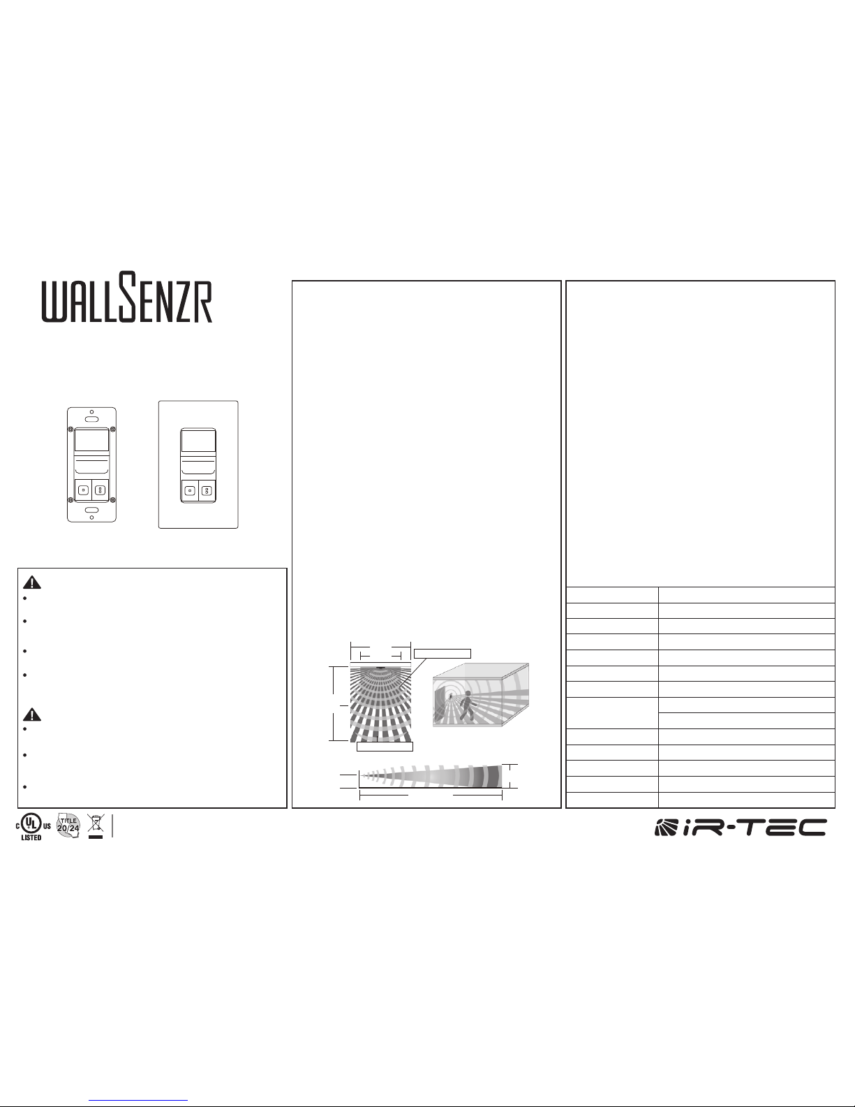
DETECTION COVERAGE
40’
Top view
Side view
4’
7’
30’
40’
Minor motion
20’
20’
Major motion
180°, 30 ft x 40 ft (W x L)
Turn power OFF at circuit breaker before installing Power Pack
or Sensors.
Do NOT touch the square window of infrared sensor under the
lens assembly.
WARNING:
Do Not Install To and/or Cover a Junction Box Having Class 1, 3 or
Power and Lighting Circuits
Class 2 Device Wiring Only – Do Not Reclassify and Install as Class 1,
3 or Power and Lighting Wiring
Coupez l'alimentation au disjoncteur avant d'installer Power
Pack ou capteurs.
Ne PAS toucher la fenêtre carrée de capteur infrarouge sous
l'ensemble de l'objectif
AVERTISSEMENT :
Classe 2 Câblage de périphériques Seulement - Ne PAS reclasser et
installer Classe 1, 3 ou alimentation et circuits d'éclairage
WARNING & CAUTION
AVERTISSEMENT & PRUDENCE
INSTALLATION
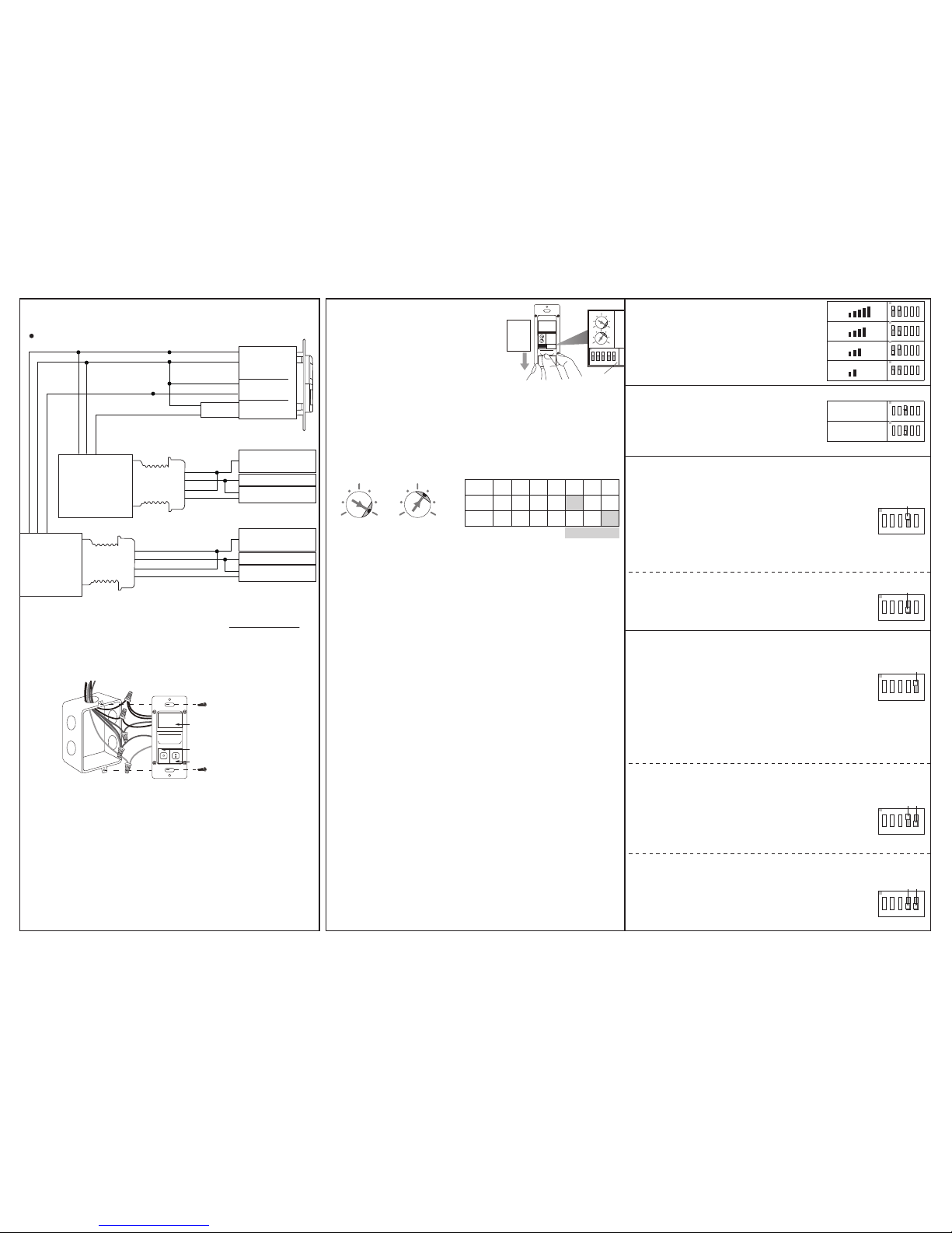
WIRING DIAGRAM
Sensor control ON/OFF
(PPU-300/301)
The sensor may be available with other control options,
consult a qualified electrician or contact info@irtec.com
for assistance.
Hot
Black
White
Red
Red
Neut
Relay
Relay
DC24V
GND
Control
Manual
Hold ON
Hold OFF
Load
Hot
120~277V
Neutral
Hot
Black
White
Red
Red
Neut
Relay
Relay
DC24V
GND
Control
Manual
Hold ON
Hold OFF
Load
Hot
120~277V
Neutral
Circuit 1
Circuit 2
Red
Black
Green
Green
White
White
Red
Black
Blue
DC+
GND
COM
NO
COM
NO
Circuit 1
Circuit 2
Black
PPU-300/301
PPU-300/301
Install the power pack and connect the load according
to its instructions.
Connect the low voltage wires of power pack with the
respective wires of the sensor according to the diagram
of desired control.
Turn on the line voltage power for the power pack.
Conduct sensor operation test.
Attach the wallplate cover after testing and setting
completed.
1.
2.
3.
4.
5.
LENS
POLE-2 PUSH-BUTTON
POLE-1 PUSH-BUTTON
TIME setting determines the delay time that the sensor will
hold the load ON after the last motion detected. Factory
setting is 10 minutes, and it can be changed by pointing the
arrowhead of potentiometer to the specific position.
TIME - Delay time
LUX setting determines the threshold of ambient light level
that the sensor will inhibit switching on the load. The factory
setting is ALS disabled (24 Hr) for testing convenience,
and it can be changed by pointing the arrowhead of
potentiometer to the specific position.
LUX – Ambient light level
TESTING
Restore the line power for sensor operation and wait for
the sensor to warm-up (GREEN LED will blink during the
warm-up period).
Move within the desired range and observe the sensor
detection. BLUE blink indicates the PIR sensor detected,
and GREEN blink indicates the HFD sensor detected.
Move outside of the desired range and observe if the HFD
sensor can detect. If GREEN LED blinks, reducing the
HFD sensitivity accordingly.
Replace the wall plate cover after sensor testing and
setting completed.
1.
2.
3.
NOTE: The connected load will be switched ON as delay
time set (factory default 10 minutes) after the power applied.
The delay time can be set to the shortest (10 seconds) for test
convenience. Ensure to set the TIME back to the desired
delay for optimum operation after test.
To program the sensor control
mode or change the settings,
press the push-button cover and
slide it down as shown.
The combinations of DIP
switch 1 and 2 determine the
sensitivity of HFD sensor.
SETTING DIP Switch
HFD Sensitivity
- SW1 & 2
- SW3
- SW4
- SW5
DIP switch 3 changes the operating
sensor. If necessary, the BDT-700 can
be programmed as a single HFD wall
switch sensor.
Sensor will turn ON the load of pole-1 when it
detects the presence of occupant, and turn OFF
automatically if no occupant motion is detected
before the time delay elapses. The ambient light
sensor (ALS) will inhibit switching ON the load if
ambient light level is higher than the set threshold.
VSOC requires occupant to press the pole-2
push-button to turn ON the connected load of
pole-2, and sensor will automatically switch OFF
the load if no occupant motion is detected before
the time delay elapses.
NOTE: The sensor will automatically turn ON the light if it detects
occupant activity within 30 seconds after time delay elapsed.
Sensor will control the load of pole-1 as in OSAC,
but with ALS and Presentation Mode (PM) both
active.
Operating Sensor
Pole-1 Control Mode
Occupancy Sensing with ALS Control (OSAC)
Vacancy Sensing Only Control (VSOC)
The sensor will automatically turn ON the
connected load of pole-2 when ambient light is
lower than the LUX level set, and turn OFF the load
automatically when ambient light is higher than
the threshold set.
Ambient Light Sensing Only (ALSO)
The sensor will control the load of pole-2 as per
pole-1 is set, but with an Extended Delay for 5
minutes.
Pole One with Extended Delay (POED)
Occupancy Sensing with ALS & PM (OSAP)
Pole-2 Control Mode
Slide
ON
12
3 4 5
TIME
LUX
Press
&
DIP
Switch
ON
1 2
3 4 5
TIME
LUX
ON
1 2
3 4 5
ON
1 2
3 4 5
ON
1 2
3 4 5
ON
1 2
3 4 5
PIR & HFD
HFD only
ON
1 2
3 4 5
ON
1 2
3 4 5
SW5=ON
ON
1
SW5
2
3 4 5
SW5=OFF
SW4=ON
ON
1
SW5
2
3 4 5
SW4
SW5=OFF
SW4=OFF
ON
1
SW5
2
3 4 5
SW4
SW4=ON
ON
1
SW4
2
3 4 5
SW4=OFF
ON
1
SW4
2
3 4 5
LUX
1 7
2 6
3 5
4
TIME
1 7
2 6
3 5
4
LUX
TIME T
POS. 1 2 3 4 5 6 7
1’ 3’ 5’ 10’ 20’ 30’
10 20 35 50
100 150 24H
Factory Set
 Loading...