

Page 1

ON-PPU-301
OS-NET Power Pack & Load Controller
INSTALLATION INSTRUCTIONS
ONLY QUALIFIED
ELECTRICIANS
SHOULD INSTALL
THIS DEVICE.
Indoor dry location use only
Utilisation a L'interieur Uniquement
WARNING & CAUTION
TURN POWER OFF AT CIRCUIT BREAKER BEFORE INSTALLING THIS DEVICE.
Install this device at least 1 ft. away from any occupant.
Risk of Electric Shock – More than one disconnect switch may be required to
de-energize the equipment before servicing.
Use UL listed wires for all wiring connections. Low voltage wiring connection should
use at least 22 AWG wire. Load switching wiring connection should use at least 12
AWG. AC power line voltage wiring connection should use at least 18 AWG wire. Wire
all Class 2 circuits using types CL3, CL3P, CL3R, or equivalent conductors. For plenum
return ceilings, use UL listed plenum-approved cables.
Always check national, state and local building codes for necessary compliance.
After initial wiring is complete, ensure to verify all the low and high voltage wires are
correctly connected before applying the power. Incorrect wiring could possibly cause
permanent damage to the power pack, lighting system, occupancy sensors or other
control devices.
AVERTISSEMENT & PRUDENCE
COUPER LE COURANT AU DISJONCTEUR AVANT D'INSTALLER BLOCS
D’ALIMENTATION.
Risque de choc électrique – Plus d'un interrupteur peut être nécessaire pour mettre hors
tension le matériel avant l'entretien.
Utiliser homologation UL fils pour toutes les connections de câblage. Basse tension
connection de câblage doit utiliser au moins 22 fils de AWG. Commutation de charges
connections de câblage doit utiliser au moins 12 AWG. Tension de la ligne de courante
alternative connections de câblage doit utiliser au moins 18 fils de AWG. Brancher tous
les circuits de classe 2 à l'aide de types CL3, CL3P, CL3R, ou conducteurs équivalent.
Pour les plafonds de retour de plénum, utiliser UL câbles ignifuges approuvés énuméré.
Toujours vérifier les codes de constructions nationaux, étatiques et locales pour le
respect nécessaire et conformité. Après le câblage initial est terminé, assurez-vous de
vérifier que tous les fils basse et haute tension sont connectés correctement avant
d'appliquer la puissance. Un câblage incorrect pourrait causer des dommages
permanents à la batterie d'alimentation, système d'éclairage, aux détecteurs de
présence ou autres dispositifs de commande.
ENCLOSED ENERGY
MANAGEMENT EQUIPMENT
4ZS9
INTRODUCTION
The ON-PPU-301 is an OS-NET enabled
power pack and plug load controller featuring
wireless mesh network capability to provide
top-notch intelligent lighting control. This
power pack not only supplies 24 VDC power
for IR-TEC’s low voltage occupancy sensors,
but also provides load switching up to 20A
upon receiving control signals from wired
sensors, or wireless commands from
networked OS-NET devices of the same
group. A unique radio command will be
transmitted to other OS-NET devices for
executing coordinated group controls
whenever ON-PPU-301 receives a control
signal from a wired sensor.
This device can be attached to a junction
box, cable tray, or fixture through a 1/2 inch
knockout with the designed threaded nipple
and locknut. Subject to the wiring connection
and control setting, the ON-PPU-301 can be
programmed to provide occupancy or
vacancy sensing control to the connected
Federal Communication Commission Interference Statement
FCC ID: NRIRS330100
This device complies with Part 15 of the FCC Rules. Operation is subject to the
following two conditions: (1) This device may not cause harmful interference, and (2)
this device must accept any interference received, including interference that may
cause undesired operation.
This equipment has been tested and found to comply with the limits for a Class B
digital device, pursuant to Part 15 of the FCC Rules. These limits are designed to
provide reasonable protection against harmful interference in a residential installation.
This equipment generates, uses and can radiate radio frequency energy and, if not
installed and used in accordance with the instructions, may cause harmful interference
to radio communications. However, there is no guarantee that interference will not
occur in a particular installation. If this equipment does cause harmful interference to
radio or television reception, which can be determined by turning the equipment off
and on, the user is encouraged to try to correct the interference by one of the following
measures:
-Reorient or relocate the receiving antenna.
-Increase the separation between the equipment and receiver.
-Connect the equipment into an outlet on a circuit different from that to
which the receiver is connected.
-Consult the dealer or an experienced radio/TV technician for help.
FCC Caution: Any changes or modifications not expressly approved by the party
responsible for compliance could void the user's authority to operate this equipment.
This transmitter must not be co-located or operating in conjunction with any other
antenna or transmitter.
Radiation Exposure Statement:
This equipment complies with FCC radiation exposure limits set forth for an
uncontrolled environment. This equipment should be installed and operated with
minimum distance 20cm between the radiator & your body.
This product may be covered by one or more U.S. patents or patent applications.
Please visit www.irtec.com for more information.
P/N: Z50-00516-000 Printed in Taiwanwww.irtec.com
light or plug load control for codes
compliance. Numerous control settings,
including burn-in time, delay time,
group/ungroup, lock/unlock…etc. can be
intuitively configured via a 2-way handheld
remote programmer.
With ON-PPU-301, you can easily enable
wireless smart lighting control with IR-TEC
low voltage occupancy sensors. Zone
lighting and plug load control can be easily
done at any junction box or fixture.
Combining the ON-PPU-301 with the
OS-NET Button gives unparalleled flexibility
and ease for room control. Whether it is a
new construction or retrofit project, OS-NET
will save time in installation, commissioning,
and user adoption.
SPECIFICATIONS
Power supply
DC power output
Maximum load
Control signal
Wireless protocol
Radio frequency
Radio range
Remote range
Op. humidity
Op. temperature
Dimensions
Purpose of control
Type Action
External Pollution
Situation
Rated Impulse
Voltage
120/277 VAC, 60 Hz
24 V, 100 mA max.
1 HP @120VAC
1 HP @ 240VAC
20A Resistive @ 120/277VAC
20A Ballast @120/277VAC
Dry contact or active low open collector
Modified Zigbee Light Link (ZLL)
2.4 GHz
Typical 15 m (50 ft.) @ indoor
Typ. 10 m (33 ft), indoor with no backlight
Max 95% RH
-20°C ~ 55°C (-4°F ~ 122°F)
111 x 90 x 46 mm (4.37” x 3.54” x 1.80”)
Operating Control with Electronic
Independently Mounted
Type 1
Pollution Degree 2
4000 V
PRELIMINARY
Programming Guide
SETTING
The ON-PPU-301 can be configured
to link with other OS-NET devices
wirelessly to execute specific
control via SRP-281. For more
details about remote operation,
please refer to the OS-NET Programming Guide
available from www.irtec.com.
Settings Description Options
INDIV-SET To setup an individual device
GROUP-SET To setup all devices of the
CONTROL Control schemes
DELAY Delay time that
group with same settings
available for ON-PPU
ON-PPU will turn off load
ON/OFF, VSC, PLC
30 sec./1/3/5/10/15/
20/30/60 min.
INSTALLATION
Low voltage wires
Line voltage wires
Load switching wires
IMPORTANT!
1.
All line voltage wiring connections should be
made inside of junction box.
2.
To obtain optimal wireless communication,
avoid placing the device behind a metal
mesh/plate.
To enable wireless network control, the
3.
ON-PPU-301 must be grouped and linked with
the other OS-NET devices. An “ungrouped”
ON-PPU-301 with low voltage occupancy
sensor connected will only operate in
standalone control.
Default
ON/OFF
20 min.
Page 2
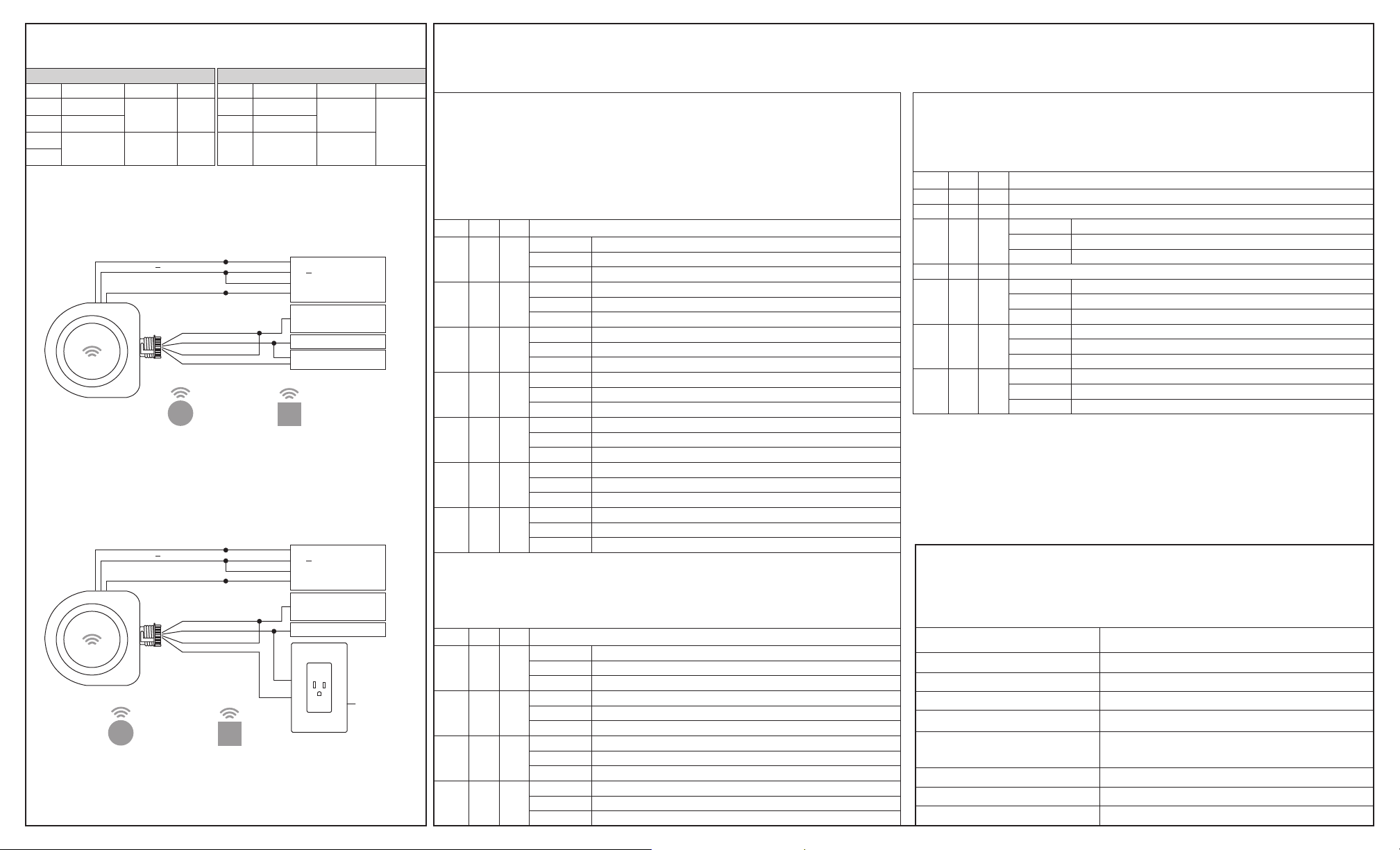
WIRING DIAGRAMS
Line Voltage Wires
Color Description Function Gauge
Neutral
White
Line
Black
Red
Relay
contacts
Red
Following are basic wiring diagrams for typical controls, consult with an
IR-TEC team member for correct wiring diagram if a more complex control is
required.
Line
voltage
Load
switching
Color Description Function Gauge
Red
18
AWG
Black
Blue
12
AWG
A. Occupancy/Vacancy Sensing Control
Red (
DC24V)
Black (
DC )
Blue (
Control)
Black (
Line)
White (Neutral)
Red (
Relay)
Red (
Relay)
S
OS-NET Sensor OS-NET Button
NOTE: For Vacancy Sensing Control (VSC), at least one OS-NET Button
should be installed and grouped with the ON-PPU-301 to enable
manual-on control.
B. Plug Load Control
Red (
DC24V)
Black (
DC )
Blue (
Control)
Black (
Line)
White (Neutral)
Red (
Relay)
Red (
Relay)
S
OS-NET Sensor OS-NET Button
NOTE: If PLC is selected, the OFF-command from OS-NET Button will
be ignored.
B
Low Voltage Wires
DC24V
DC-
Control
DC power
supply
Sensor
signal input
Red
DC+
Black
DC
Green
COM
White
NO
Line
120/277V
Neutral
Load
B
Red
DC+
Black
DC
Green
COM
White
NO
Line
120/277V
Neutral
N
L
IR-TEC
Low Voltage
Occupancy
Sensor
IR-TEC
Low Voltage
Occupancy
Sensor
Ground
G
24 AWG
Class 2
CONTROL SCHEME
The following schemes can be programmed via CONTROL setting of the SRP-281. Depending on the connection of wired Low Voltage Occupancy Sensor (LVOS) and
grouped OS-NET Sensor (ONS)/OS-NET Button (ONB), the ON-PPU may control the load in slightly different patterns.
CONTROL = ON/OFF
The load will be switched ON when ON-PPU receives 1) control signal from a wired
LVOS, or 2) wireless command from a grouped ONS/ONB, and switched OFF when
programmed delay time elapses or receives the OFF-command from a grouped OSB.
If the load was switched OFF via an OSB, the ON-PPU will operate in Presentation
Mode. The load will remain OFF if motion is detected before the delay time elapse.
The ON-PPU will resume to auto-ON, auto-OFF control after delay time elapsed.
“√” means “one or more units connected/grouped”
LVOS ONS ONB ON-PPU-301 Operations
√
√
√ √
√ √
√ √ √
Load ON
Load OFF -Delay reset
Load ON
Load OFF -Delay reset
Load ON
Load OFF --
√
Delay reset
Load ON
Load OFF Delay reset
Load ON
Load OFF -
√√
Delay reset
Load ON
Load OFF Delay reset
Load ON
Load OFF
Delay reset
Any LVOS detects occupancy
Last active LVOS delay elapses
Not activated
Any ONS detects occupancy
ON-PPU delay elapses
When ONS detects occupancy
Any ONB is pressed ON
ON-PPU delay elapses or ONB is pressed OFF
When ONB is pressed ON
Any LVOS/ONS detects occupancy
Both LVOS and ON-PPU delays elapse
When ONS detects occupancy
Any LVOS detects occupancy or ONB is pressed ON
Last LVOS delay elapses or ONB is pressed OFF
When ONB is pressed ON
Any ONS detects occupancy or ONB is pressed ON
ON-PPU delays elapse or ONB is pressed OFF
When ONS detects occupancy or ONB is pressed ON
Any LVOS/ONS detects occupancy or ONB is pressed ON
Both LVOS and ON-PPU delays elapse or ONB is pressed OFF
When ONS detects occupancy or ONB is pressed ON
CONTROL = VSC
VSC refers to Vacancy Sensing Control. This control requires user to turn ON the load
by pressing a grouped OSB, and the ON-PPU will turn OFF the load when delay time
elapses or receives the OFF-command from a grouped OSB.
LVOS ONS ONB ON-PPU-301 Operations
√
√ √
√ √ √
√
√
Load ON
Load OFF - Delay reset
Load ON
Load OFF Delay reset
Load ON
Load OFF Delay reset
Load ON
Load OFF
Delay reset
Any ONB is pressed ON
ON-PPU delay elapses
When ONB is pressed ON
Any ONB is pressed ON
Both LVOS and ON-PPU delays elapse or ONB is pressed OFF
When ONB is pressed ON
Any ONB is pressed ON
ON-PPU delays elapse or ONB is pressed OFF
When ONS detects occupancy or ONB is pressed ON
Any ONB is pressed ON
Both LVOS and ON-PPU delays elapse or ONB is pressed OFF
When ONS detects occupancy or ONB is pressed ON
CONTROL = PLC
PLC refers to Plug Load Control. The ON-PPU will enable the plug load power when it
receives 1) control signal from a wired low voltage occupancy sensor, or 2) wireless
command from a grouped OS-NET Sensor/Button, and switch OFF the plug load
power after the area is vacant and programmed delay time elapsed.
LVOS ONS ONB ON-PPU-301 Operations
√
√
√
√
√
√
√ √ √
NOTE
The DELAY timer of ON-PPU will only be activated by receiving the wireless command
1.
from grouped OS-NET devices.
2.
The ON-PPU will transmit OCC signal wirelessly for group control when wired LVOS
detects occupancy.
3.
To prevent unintentionally shutting off the power for plug load control, ensure to set the
DELAY of the ON-PPU longer than the setting of grouped ONS.
Under PLC mode, all OFF-command from the OS-NET Button will be ignored.
4.
Same as ON/OFF control-Same as ON/OFF control-Load ON Any ONB is pressed ON
Load OFF -- ON-PPU delay elapses
√
Delay reset When ONB is pressed ON
Same as ON/OFF ControlLoad ON Any LVOS detects occupancy or ONB is pressed ON
Load OFF - Last LVOS delay elapses
√
Delay reset When ONB is pressed ON
Load ON -Any ONS detects occupancy or ONB is pressed ON
Load OFF ON-PPU delay elapses
√
Delay reset When ONS detects occupancy or ONB is pressed ON
Load ON Any LVOS/ONS detects occupancy or ONB is pressed ON
Load OFF Both LVOS and ON-PPU delays elapse
Delay reset When ONS detects occupancy or ONB is pressed ON
DEVICE LED ACKNOWLEDGEMENT
The device will acknowledge the setting success or failure with following
indications by device LED in BLUE or GREEN. BLUE means the device is
unlinked and GREEN means the device is network linked.
DEVICE LED ACKNOWLEDGEMENT
LED on Control scheme is set to ON/OFF sensing control
Slow blinking (on-off per 0.5 second) Control scheme is set to vacancy sensing control (VSC)
Blinks twice every 2-second Control scheme is set to plug load control (PLC)
Blinks irregularly in BLUE or GREEN Receiving commands from the remote
Fast blinking in BLUE and GREEN
intermittently
Blinks slow once and fast twice The device is under test mode
Blinks slow once and fast once The device is under burn-in mode
Lit for 2 seconds in GREEN Grouping/setting is completed
Scanning for an open network and linking
 Loading...