

Page 1

R
PLATO
Passive Infrared Detector
IR-580/580C/580CS
Installation Instructions
INTRODUCTION
Thank you for choosing PLATO series passive infrared
detector. This motion detector is designed to provide
reliable intruder detection for today’s security system.
To ensure optimum performance of this device, please
read all contents carefully before installing. Improper
installation may result in false operation.
INSTALLATION HINTS
Do not install the detector at
where faces direct or reflected
sunlight or windows with direct
car headlight.
Ensure that there are no
obstructions (plants, screens,
furniture etc.) in the field of view
that may cause incorrect
cover/operation of the detector.
Avoid locating the detector in
areas where contain equipment
that may change the environment temperature rapidly.
Install the detector at proper
height on a rigid surface. Do
not install the detector on
vibrating surface.
PIR detector is more sensitive to
the motions “across” the
detection zones than “toward”
or “away” the unit.
DESCRIPTION
PCB fixing screw
Corner mount knockout
s
Cable access
Wiring terminals
Tamper switch
PCB position pointer
Cover locking screw
Infrared sensor
(Do not touch!)
Alarm output selector
Pulse count selector
LED on-off switch
Mounting bracket fixing
INSTALLATION
DIRECT WALL/CORNER MOUNT
1. Open the front cover by releasing the cover
locking screw.
2. Carefully remove the PCB from the unit base.
3. Knock out the mounting holes with proper tool.
4. Drill the holes on wall. Lead the cable through
access hole and mounts the unit base firmly.
5. Replace the PCB to the unit base and complete
the wiring as the next paragraph described.
CEILING/WALL MOUNT WITH BRACKET
1. Mount the bracket base on ceiling or wall. Lead
the cable through central well.
2. Open the front cover of the detector by releasing
the cover locking screw.
3. Carefully remove the PCB from the unit base.
4. Fix the unit base of detector and the swivel arm of
mounting bracket with provided screws.
5. Lead the cable through the wire tunnel into the
unit base. Assemble the unit base with the bracket
base.
2.4m (8 feet)
(Approx)
6. Replace the PCB to the unit base and complete
the wiring as the next paragraph described.
WIRING CONNECTION
After the installation completed. Connect the wires to
the corresponding terminals according to the following
instructions.
+
, –
: 9 ~ 16 VDC power supply
ALARM : Zone input of control panel (N.C/N.O)
TAMPER : Tamper loop of control panel (N.C).
Replace the front cover, apply power supply to the
detector to conduct the walk test.
WALK TEST
The walk test should be carried out to ensure proper
detection coverage. Apply DC power to the detector
and wait at least 60 seconds for sensor to warm up.
Walk across the detection zones at normal speed. The
LED will light whenever it detects the movement. To
disable the LED, just remove the jumper head from the
pins marked “LED”.
Page 2
PULSE COUNT
The detector features an intelligent pulse count that
reduces the possibility of false alarm caused by
environmental and power line interference. The pulse
count can be set to count 2 or 3 pulses by placing the
jumper head on or off the corresponding pins. The
alarm signal will only be sent when the selected pulses
are generated within delay time of 20 seconds. IRTEC‘s intelligent pulse count circuitry analyzes the
width difference of pulse signal. When human motion
is detected a subsequent pulse signal
will over-ride the pulse count setting
and generate the alarm signal without
any delay.
ALARM OUTPUT SELECTION
The alarm output of this detector can be changed from
NC (normally closed) to NO (normally open) by
removing the jumper head from the pins. NC format is
generally used in the intruder alarm system; NO format
can be used for alarm event recording or other
automatic control applications.
RANGE ADJUSTMENT
The detection zones can be vertically adjusted by
sliding the PCB up or down. If the unit is mounted
higher than 2.7m (9 feet), it maybe necessary to slide
the PCB upwards to tilt the detection zones
downwards to obtain optimum detection coverage. If
the unit is mounted lower than 2.1 (6 feet), it maybe
necessary to move the PCB downwards to tilt the
detection zones upwards. Please refer to the following
table to get the adequate PCB position for the
respective maximum detection coverage with various
mounting heights.
For IR-580 w/o bracket
M/H 1.8m 2.0m 2.2m 2.4m 2.6m 2.8m 3.0m
B/P Maximum Detection Coverage(m)
+2 15 15 15 15 15 12 15
+1 15 15 15 15 13 15 15
0 15 15 15 15 15 15 15
-1 14 15 15 15 15 15 15
-2 13 14 14 15 15 15 14
-3 10 11 12 14 13 14 9
-4 8 9 11 11 12 13 8
M/H: Mounting Height B/P: PCB Position
Note: The detection range might be reduced under
high room temperature.
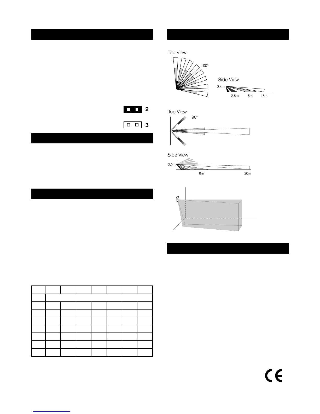
DETECTION PATTERN
IR-580
IR-580C
IR-580CS
15m
2.4m
SPECIFICATIONS
Infrared sensor..............Dual element
Power supply................9 ~ 16 VDC, 12V typical
Current drain.................NC: 15mA, NO: 8 mA, 12VDC
Alarm output .................NC/NO, 30VDC, 0.2A max.
Alarm period .................1.5 ~ 2.5 sec.
Pulse count...................2 / 3 selectable
Tamper switch ..............NC, cover open activates
Walk test LED ...............Blue, can be disabled
RFI immunity.................Ave. 25V/m (10~1000 MHz)
Detectable speed..........0.3 ~ 1.5m/sec.
Mounting height............W/o bracket: 1.8~3.0m
With bracket: 1.8~3.6m
Humidity........................95% RH maximum
Temperature .................-20°C ~ 60°C (-4°F ~ 140°F)
Dimensions...................100 x 60 X 42 mm
Unit weight....................68 grams
* Specifications are subject to change without prior notice.
06/29/05’ 058-58000-001
 Loading...