

Page 1
T
M
Security & Automation Management System
INSTALLATION & OPERATION MANUAL
To provide optimal performance of this security system, please read all
contents of this manual carefully before installing and operating. Improper
operation or system setting may result in inferior performance of the system.
V 1.4
Page 2

TM
2
CONTENTS
1. INTRODUCTIONS.........................................................................................3
2. FEATURES....................................................................................................3
3. SYSTEM DESCRIPTION...............................................................................4
3.1 System devices.................................................................................................... 4
3.2 Main controller ..................................................................................................... 6
3.3 Status indications ................................................................................................ 7
3.4 Detectors/zones categories................................................................................. 7
4. INSTALLATION.............................................................................................8
4.1 Mechanical installation ........................................................................................ 8
4.2 Electrical installation ............................................................................................ 8
5. USER OPERATION.......................................................................................9
5.1 Operation interface .............................................................................................. 9
5.2 Operation code (password) ................................................................................ 10
5.3 Initial state ............................................................................................................ 11
5.4 System check ...................................................................................................... 12
5.5 Master mode........................................................................................................ 15
5.6 Operation modes................................................................................................. 17
5.6.1 AWAY mode ................................................................................................. 17
5.6.2 HOME mode................................................................................................. 17
5.6.3 DISARM mode.............................................................................................. 18
5.7 Alarm reactions.................................................................................................... 18
5.8 Answering phone call .......................................................................................... 19
5.9 Dial-in control....................................................................................................... 20
6. INSTALLER SETTINGS ................................................................................22
6.1 Timer settings ...................................................................................................... 22
6.2 Telephone settings .............................................................................................. 24
6.3 Sound settings..................................................................................................... 28
6.4 System device settings........................................................................................ 29
6.5 Siren settings ....................................................................................................... 33
6.6 Miscellaneous settings ........................................................................................ 34
6.7 GSM settings ....................................................................................................... 35
7. CMS SETTINGS............................................................................................36
8. EXTERNAL CONNECTIONS.........................................................................37
8.1 Remote Message Display.................................................................................... 37
8.2 RS-232 Computer Interface Connection ............................................................. 37
8.3 Ethernet Adaptor and Internet Remote Access Connection............................... 38
8.4 X-10 Power Line Interface Connection................................................................ 38
8.5 Terminal Block Connection ................................................................................. 38
8.6 GSM Module Connection .................................................................................... 39
8.7 Connecting HomeKeeper with Phone/FAX/Answering Machine........................ 39
8.8 Partial Arm for Group 91 to 99............................................................................. 40
9. SPECIFICATIONS......................................................................................... 41
10. HK-RC868 Remote Control Keyfob .............................................................. 42
11. HK-IR868 HomeKeeper PIR Motion Detector ...............................................43
12. HK-IR868P HomeKeeper PIR Motion Detector............................................. 47
13. HK-DS868 HomeKeeper Door/Window Sensor............................................ 51
14. HK-ES868 HomeKeeper Wireless External Siren .........................................53
Page 3

TM
3
1. INTRODUCTION
Thank you for choosing IR-TEC HomeKeeper IP-based wireless security & automation
management system. This system redefines the standards for convenience and peace of
mind by utilizing the latest microprocessor control and RF telecommunication technologies
to deliver many powerful features and functions to protect your valuable properties.
HomeKeeper provides not only advanced security protection, but also state-of-the-art home
automation that enable property owners to remotely verify the status of lighting devices or
even control the appliance and lighting at anyplace, anytime. In addition, the HomeKeeper
can also operate as an elderly care system and environmental safety monitoring center by
linking with optional medical help button and temperature, humidity or flood sensors.
The interactive programming technology provides ease of installation and system operation
setup for installer and experienced user. Unique HyperSecureLink software allows installer
to check the system status without visiting the site. System owner/user can also access into
the system to re-program the functions or check system status via GSM, Internet or regular
telephone network from work or vacation.
Please keep this manual at handy place for future reference.
2. FEATURES
Supervised RF radio link between system devices and Main Controller.
Responds to burglary, fire, panic, emergency, medical and environmental hazards
Off-site control operation via Internet, PSTN or GSM network.
RS-232 interface PC uploading & downloading.
Maximum 288 wireless sensors/zones plus 3 hardwire zones.
RF signal receiving level indication ensures optimum radio connection.
Advanced RF jamming detection in compliance with highest industry standard.
Hopping-code remote control key fob prevents unauthorized duplication.
Blue-LED backlit 16 x 2 characters user-friendly interactive LCD display.
Delay, Instant, Bypass, Fire, Switch control…etc. fully programmable zone
Detailed 512 alarm event log with date and time stamp.
Latchkey code informs parents when kids leave or return home.
Instant event reporting to telephone, pager CMS, GSM, SMS.
Built-in voice dialer to 10-phone, 1-pager and 2-CMS data link numbers.
Multi-million RF encryption coding and unique time frame transmissions.
Hands-free speakerphone, two-way emergency voice communication.
Dial-in control for listen-in, arm, disarm, event report and automatic switching control.
Controls up to 16 electrical devices via X-10 home automation power control module.
1-master, 7-user, 2-latchkey and 1-duress codes for various user operations.
Temperature, humidity and other sensor connections for environment safety monitoring.
Optional GSM communication module provides second-to-none security protection.
Page 4
TM
4
3. SYSTEM DESCRIPTION
HK-MC868 Main Controller and many system devices, including various types of detectors
and accessories, form the HomeKeeper Security & Automation Management System. All
radio transmitters used in the HomeKeeper system devices, except the Remote Control
Keyfob, feature with a unique code preset by the factory from total 16,777,216 combinations.
A special transmission timing control technology ensures that all system devices can
communicate with the Main Controller without interfering each other.
Note: In order to comply with the radio communication regulation in most countries, the radio
output power of each system device has been limited to maximum 10 mW. This output
level gives effective communication range up to 200 feet at open field. The
communication range may be reduced within the building, depending on the building
material, furniture and construction.
Functions of Main Controller and other system devices are described as below;
3.1 SYSTEM DEVICES
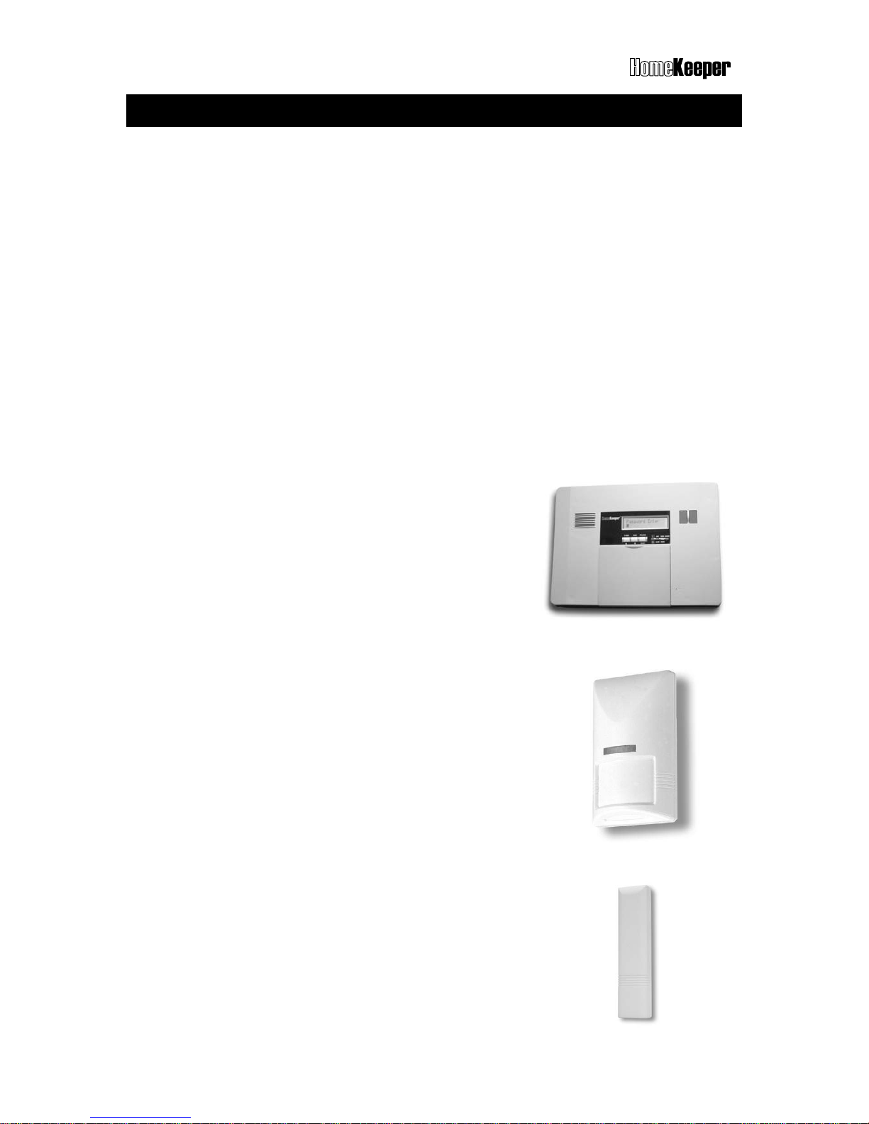
HK-MC868 HomeKeeper Main Controller
HK-MC868 is the most important command center of the
HomeKeeper system. It not only links with all system
devices by radio signal or wire, but also monitors the status
of all other devices and generates proper alarm condition
whenever necessary. Most contents of this manual are
written for the operation of this system command center.
HK-IR868 Passive Infrared Detector
HK-IR868 is a battery operated passive infrared detector
designed to detect the intruder while system is armed. It
can detect the motion of human body and report to the
Main Controller via built-in radio transmitter. The HK-IR868P
features advanced pet immune technology that is able to
immune floor movements of pets up to 18 Kg.
To correctly install the PIR detector, please refer to the
installation instruction supplied with the unit.
HK-DS868 Door/window sensor
HK-DS868 is a battery operated magnetic sensor designed
to detect the open/close status of the door/window of the
property and report to the Main Controller via its built-in
radio transmitter. To install this device, please refer to the
installation instruction of the unit.
Page 5
TM
5
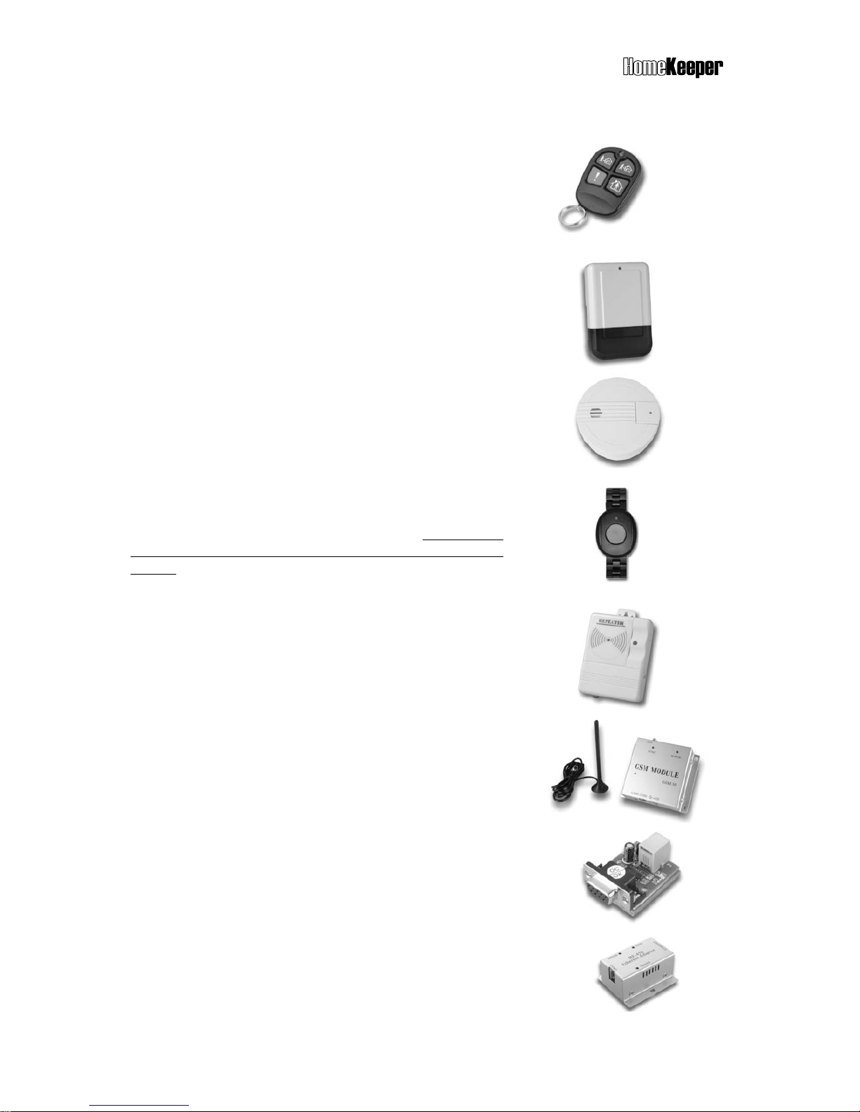
HK-RC868 Remote Control Keyfob
HK-RC868 is a remote control keyfob to arm and disarm
the system via radio frequency. It utilizes advanced
hopping code technology to provide up to 7.3 x 10
19
combinations whose radio code will change every time
when button is pressed. This advanced technology can
effectively prevents unauthorized keyfob duplicating.
Please refer to page 42 for more about using this device.
HK-ES868 Wireless External Siren
HK-ES868 is an external siren with built-in receiver, which
can be activated by radio signal. To install this device,
please refer to the installation instruction with the unit.
HK-SD868 Wireless Smoke Detector
HK-SD868 is a battery operated smoke detector with builtin RF transmitter. It will transmit the radio signal to the Main
Controller when it detects smoke in its range.
HK-MH868 Medical Help Activator
HK-MH868 is a wristband medical help activator with
built-in RF transmitter. It will transmit the radio signal to
the Main Controller if the button is pressed. Please keep
this device out of reach of children to avoid unwanted
trigger.
HK-SR868 Radio Signal Repeater
HK-SR868 is a radio signal repeater, which can be used to
relay the RF communication signal between system
devices and Main Controller. This device can be used to
extend the radio communication range for HomeKeeper.
HK-GSM30 GSM Communication Module
HK-GSM30 is a GSM communication module for
HomeKeeper to connect with GSM network. This device is
actually a working GSM mobile phone after insert a valid
SIM card.
HK-RS232 RS-232 Interface Module
HK-RS232 is a RS-232 interface module for HomeKeeper to
communicate with PC.
HK-BF450 Ethernet Interface Module
HK-BF450 is an Ethernet interface module for HomeKeeper
to hook on LAN (Local Area Network).
Page 6
TM
6
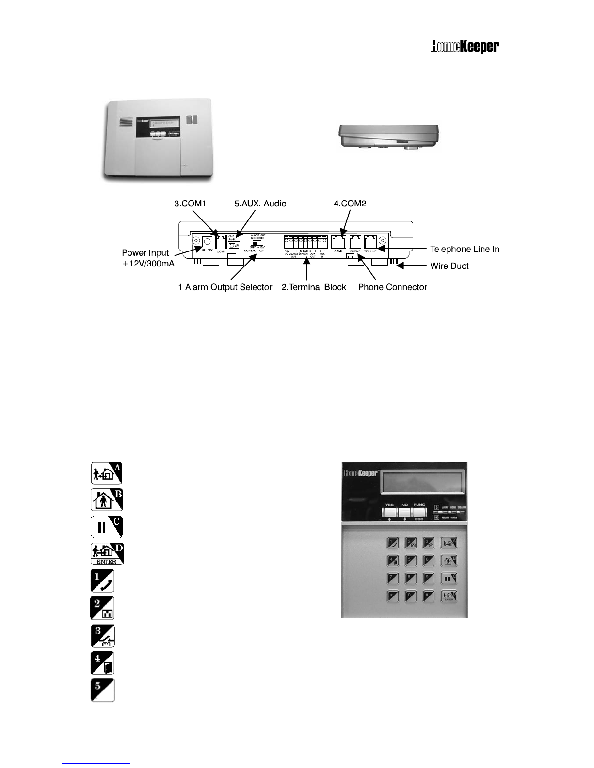
3.2 MAIN CONTROLLER
Front view Side view
Top view
1. A
larm Output Selector: Select the alarm relay output as 12 VDC or dry contacts.
2. Terminal Block: Serial of terminal blocks for various wiring connections. Please
refer to the “EXTERNAL CONNECTIONS.
3. COM 1: Communication port for RS-232, Ethernet or GSM module. Please refer
to the “EXTERNAL CONNECTIONS”.
4. COM 2: Communication port for X-10 Power Line Interface controller. Please
refer to the “EXTERNAL CONNECTIONS”.
5. AUX Audio: Audio I/O for GSM module connection. Please refer to the
“EXTERNAL CONNECTIONS”.
Keypad and Status Display
: Key A & for AWAY mode
: Key B & for HOME mode
: Key C & for CLEAR and PAUSE
: Key D & for DISARM and ENTER
: Key 1 & for hand-free telephone
: Key 2 & for X-10 switching control
: Key 3 & for relay control
: Key 4 & for door open control (reserved)
: Key 5 & message in reading (refer to 8.1)
Page 7
TM
7
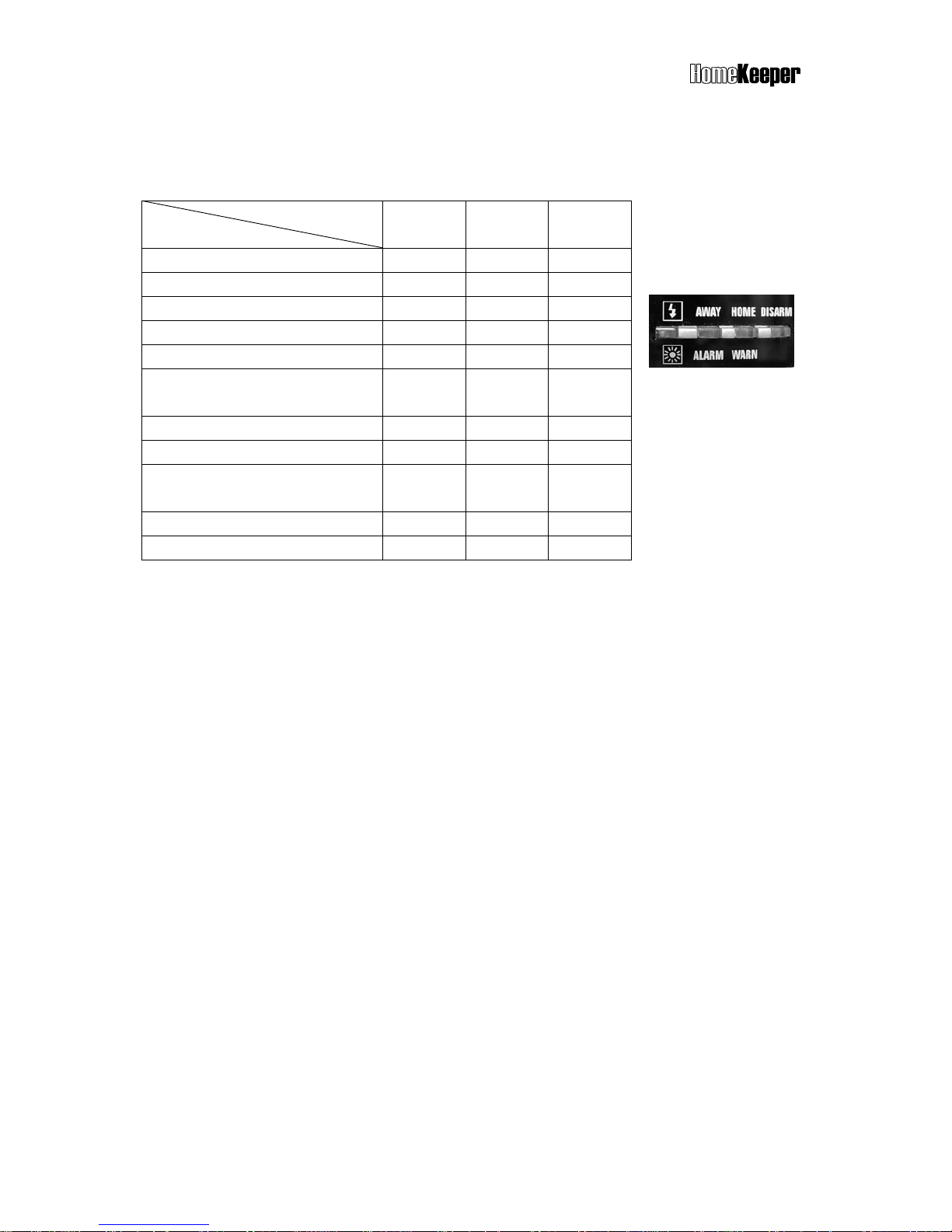
3.3 STATUS INDICATIONS
3 LED indicators (red, yellow and green) on the front panel indicate various system statuses
with different ON-OFF-FLASH combinations as the following table shown.
LED
Status
Red
(AWAY)
Yellow
(HOME)
Green
(DISARM)
DISARM mode OFF OFF FLASH
HOME mode OFF FLASH OFF
AWAY mode FLASH OFF OFF
DISARM with warning message OFF ON FLASH
DISARM with alarm message ON OFF FLASH
DISARM with warning & alarm
message
ON ON FLASH
HOME with warning message OFF ON OFF
HOME with alarm message ON Flash OFF
HOME or AWAY with warning &
alarm message
ON ON OFF
AWAY with warning message FLASH ON OFF
AWAY with alarm message ON OFF OFF
Note: If there is any alarm or warning message in the event log memory, the ALARM (red)
and WARN (yellow) LED indicators will be lit. The indications can be reset after the
user runs the Event Check function (refer to the System Event Check section) or
pressing (hotkey) in Disarm mode.
3.4 DETECTORS/ZONES CATEGORIES
The HomeKeeper system can link up to 288 wireless detectors, each defined as a zone. All
detectors should be classified into five categories as below;
1. Remote Control Keyfob, Keypad C: Controller / Panic Devices.
2. Door/Window Sensor, Passive Infrared Detector, Glass Break Detector…etc. B:
Burglar Detectors.
3. Smoke Detectors, Gas Detectors F: Fire Detectors.
4. Medical Help Transmitter and Inactivity Detector M: Medical Help Transmitters.
5. Flood Detector, Temperature Sensor and Humidity Sensor. S: Special Detectors.
The system will automatically assign a category code (C, B, F, M, S) and a two double-digit
identification code (01-01 ~ 99-99) to all system devices linked. The category code
represents type of the device. The first two-digit is referred as “Group number” and the
second two-digit is referred as “Unit number”.
For example, C 01-02 represents the Controller of Group 01, Unit 02. B 02-04 represents
the Burglar detector of Group 02, Unit 04.
Page 8

TM
8
For management and maintenance purpose, the system assigned device identification code
can be changed by installer while proceeding initial setup. User or installer can define their
preference group number as desired. Several devices can be grouped together.
Note: Group number 00 is reserved for the Main Controller.
4. INSTALLATION
4.1 MECHANICAL INSTALLATION
Placement of the Main Controller
It is important to ensure that the Main Controller is installed at place with good reception of
the RF signals transmitted from all system devices. The following notes should be taken into
consideration while selecting the location of Main Controller.
Try to place the Main Controller at the central area of the house or office.
Ensure that AC power outlet and telephone line (if needed) is available nearby.
DO NOT place the Main Controller nearby any large appliance or metallic objects.
DO NOT place the Main Controller at outdoors or where water may splash on.
1. Separate the Mounting Bracket from Main Controller by releasing the two flat head
screws.
2. Drill two mounting holes to fix the Mounting Bracket on wall.
3. Insert the plastic plug for screw mounting.
4. Attach the Main Controller to the Mounting Bracket and push up to hold the unit.
5. Fix the Main Controller and Mounting Bracket with the two flat head screws.
Installing System Devices
Before installing the system device, check the radio signal quality from the RSSI (Receiving
Signal Strength Indication) reading on the LCD by pressing the test button of the system
device (if available). Relocate the system device to obtain better RF reception is necessary.
Please refer to the respective installation instruction to install system device correctly.
DO NOT install system device on a metal surface as it will absorb the RF transmission and
result in shorter range.
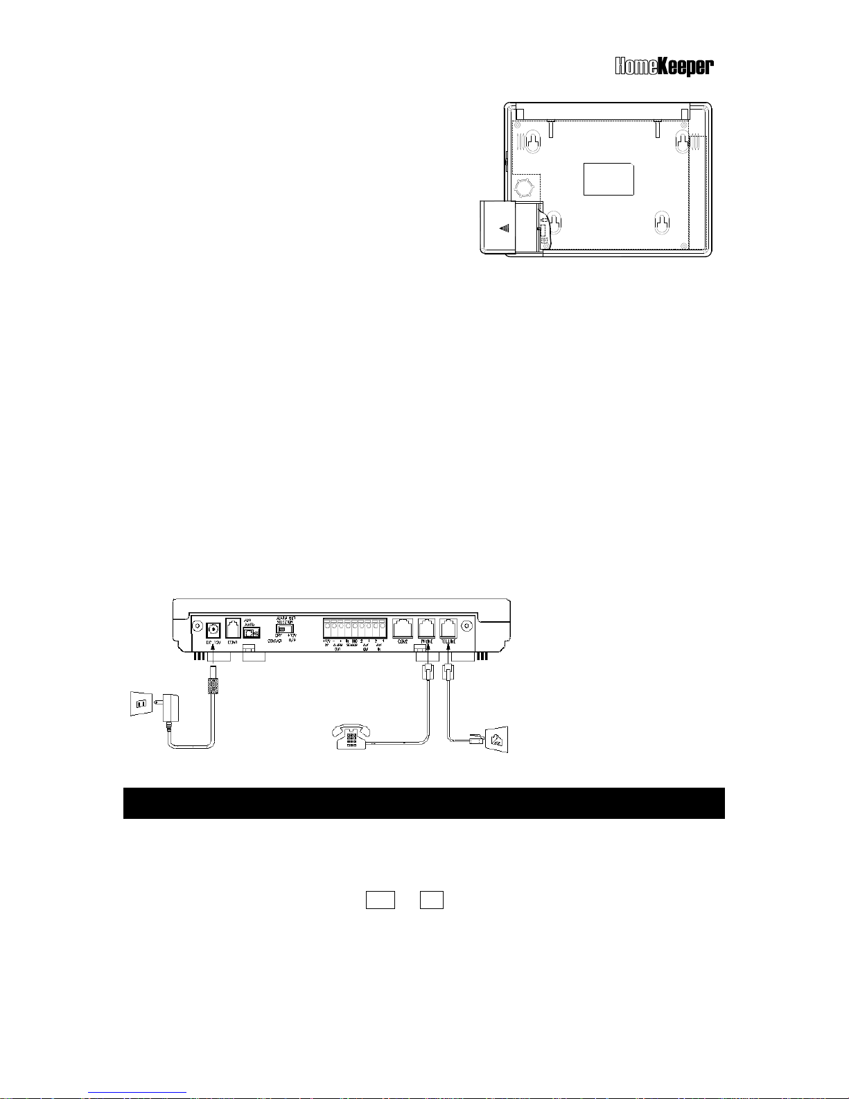
4.2 ELECTRICAL INSTALLATION
1. Open the cover of back-up battery 2 compartments located at left bottom corner (face to
the back of the unit). Slide the battery switch to the ON position.
Note: The HomeKeeper Main Controller accommodates 2 rechargeable batteries. Battery 1
(9.6V/900mA) is built-in and battery 2 (9.6V, 600mA) is optional. If AC mains power fails,
the back-up batteries can supply system operation power up to 15 hours, depending
on the system load and effective capacity of the batteries.
Page 9
TM
9
2. Plug in the AC power adaptor.
3. Enter the “INSTALLER” code (Default
INSTALLER code is “1234”) and access into
the INSTALLER SETTING mode (refer to the
Installer Setting mode).
4. Proceed the following system settings by
referring to the respective instructions.
A) Telephone number setting (refer to 6.2)
B) Voice message recording (refer to 6.3)
C) Wireless system device enrollment (refer to 6.4)
5. Set other functions if necessary (refer to the respective setting instruction).
6. Connect the telephone line, GSM module and/or Ethernet adaptor (if applicable) as this
manual and device’s installation instruction stated.
7. If Wireless Siren (optional) is installed, ensure to enroll the Main Controller into the
Wireless Siren (refer to 6.4 and instruction of the wireless siren).
8. Enter into “Master Mode” and set the system clock (refer to the 5.5 Master Mode –
Clock Setting).
9. Test other functions that have been set.
Note: Manufacturer strongly recommends the installer to complete all system settings
via “HyperSecureLink” by PC with the RS-232 interface module. All system settings
and programming can be done via “HyperSecureLink” much easier and faster.
5. USER OPERATIONS
5.1 OPERATION INTERFACE
The operation interface of HomeKeeper adopts user-friendly interactive programming
technique, so that all system settings and operations can be done easily. Just follow the
instruction on the LCD and answer YES or NO to the system by pressing the respective
button, you can complete most of the operations and programming of the HomeKeeper
system.
Page 10
TM
10
Reading the LCD instruction
When LCD displays message with question mark (?), it means that you should press
the YES or NO button to answer. Ex. The LCD shows “Master Code?”, press YES
button to enter into the Master Mode or NO to deny the command.
If the LCD displays some number and follows by “Enter”, it means that you should
input the proper figure and then pressing the Enter (D) key. Ex. The LCD shows
“Seconds (0-255) Enter:” it means the system is asking you to enter the figure
between 0 and 255, then press Enter (D) key to confirm. (If press 6, 4, and then Enter,
it means that you have set the time for 64 seconds).
To check the system function, press or key (same as YES and NO) to scroll the
screen up or down.
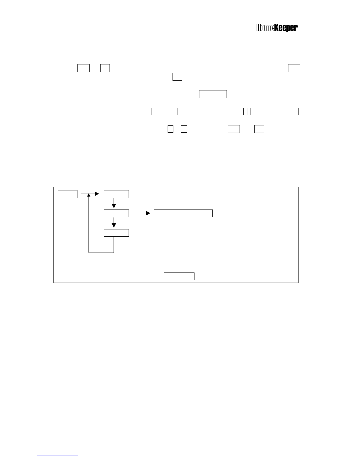
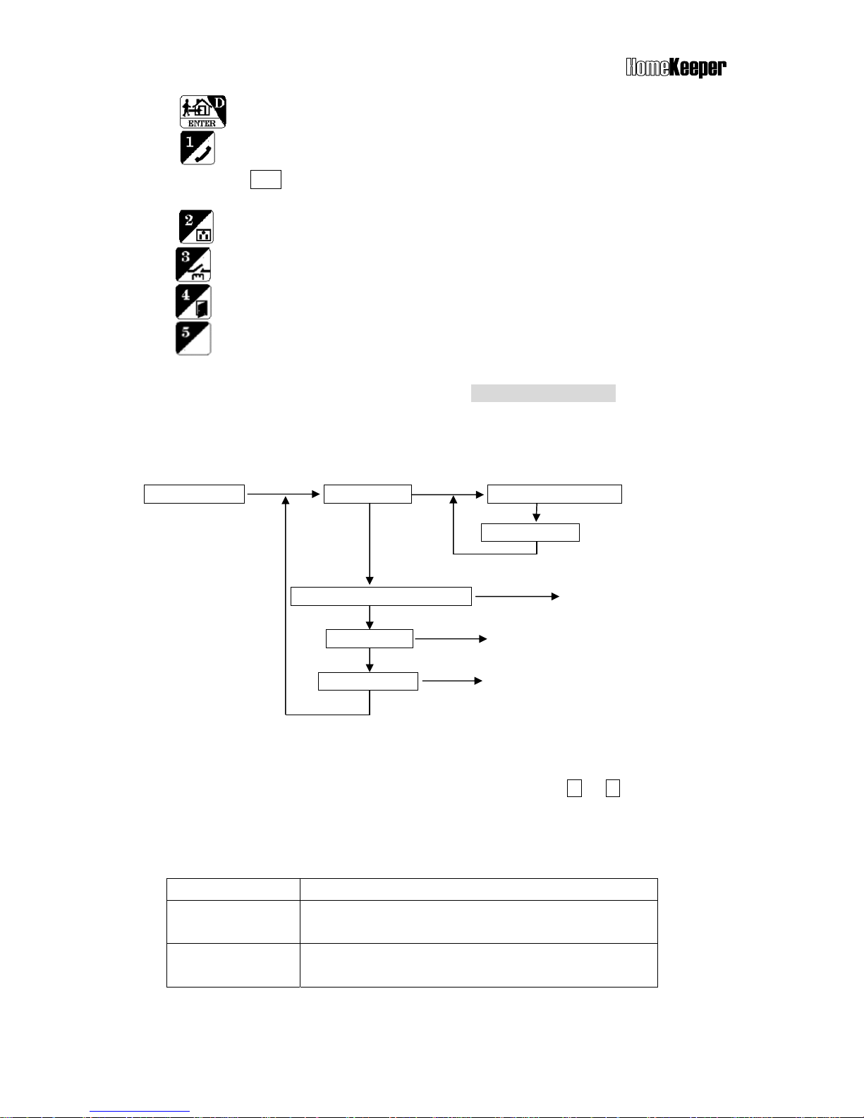
Reading the programming flow chart
In order to provide easy-to-understand description for all the programming procedures of
system operations, many programming flow charts are shown in this manual. Here we show
you how to read these flow charts.
5.2 OPERATION CODE (PASSWORD)
There are totally 14 operation codes (also refer as “PASSWORD”), each with maximum 8
digits, can be set to operate the Main Controller. Primary user (normally the property owner)
should record all details of every operation code (including code type, user’s name,
authorized date…etc) at secured place to prevent confusion in the future.
1 x Master Code (user 1, default “0000”)
This is the most important operation code of the HomeKeeper system. It has the highest
priority which allows primary user to manage other user codes and system settings.
7 x General User Codes (user 2 – 8)
These codes are available for 7 general users who are authorized to arm/disarm the system
and check the system status.
State A State A-1
State A-2
Sub-state of State A-2
State A-3
Down arrow () in all flow charts means selecting the next state. Right arrow () means
entering into the sub-state of current state.
Note: To exit the current state, pressing FUNC/ESC key at anytime.
Page 11
TM
11
2 x Latchkey User Codes (user 9 & 10)
When enter any one of these two codes to arm or disarm the system, the HomeKeeper will
dial the Latchkey Number (refer to 6.2.1 Setting Telephone Number-Latchkey number) to
report the operation.
1 x Duress Code (user 11)
If user enters this code to disarm the system, the HomeKeeper will dial and send the duress
signal to the CMS.
1 x Installer Code (default “1234”)
This code authorizes user or installer to enter into the Installer Mode for more system
settings.
2 x CMS Codes (CMS1 default “1111”, CMS2 default “2222”)
These two codes authorize CMS providers to set CMS parameter and execute system check.
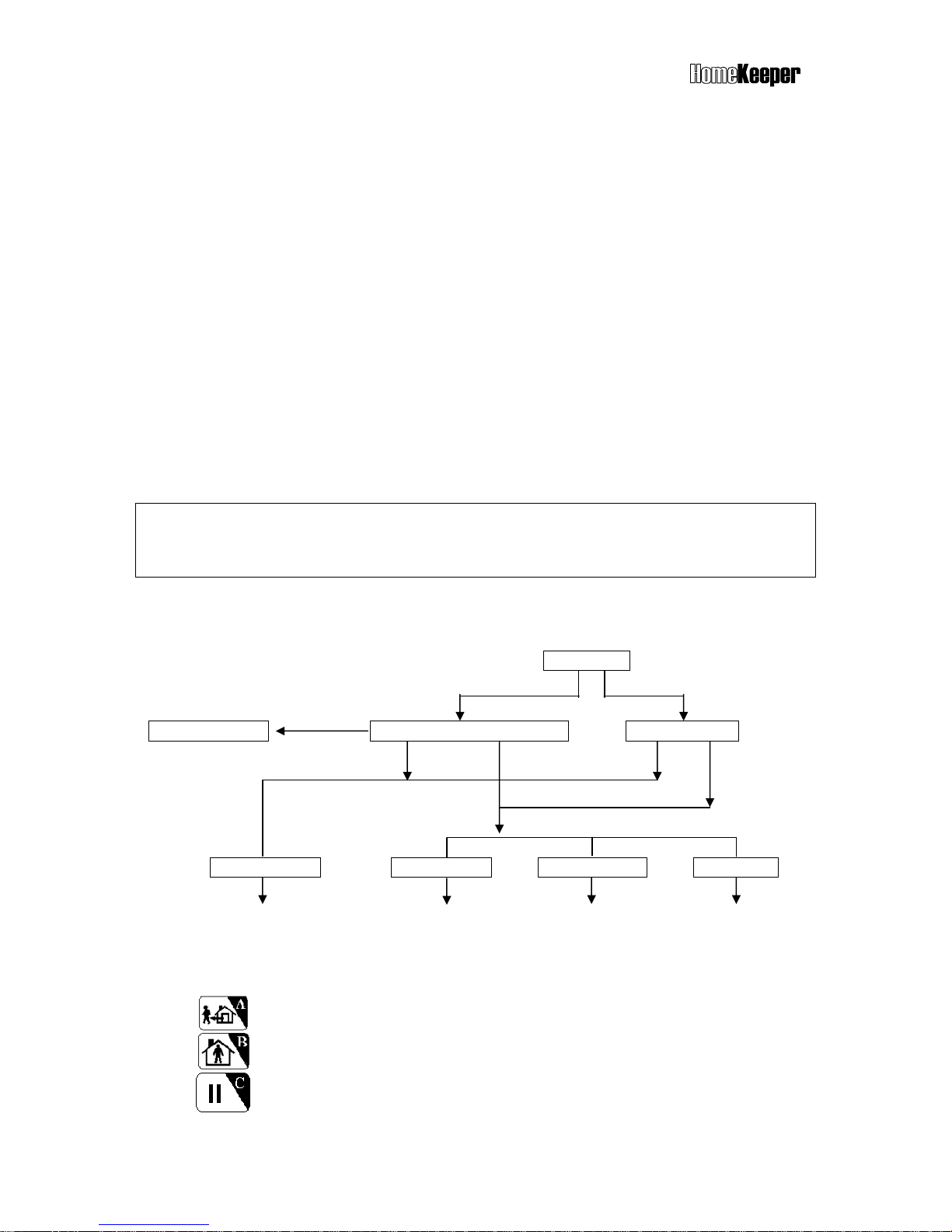
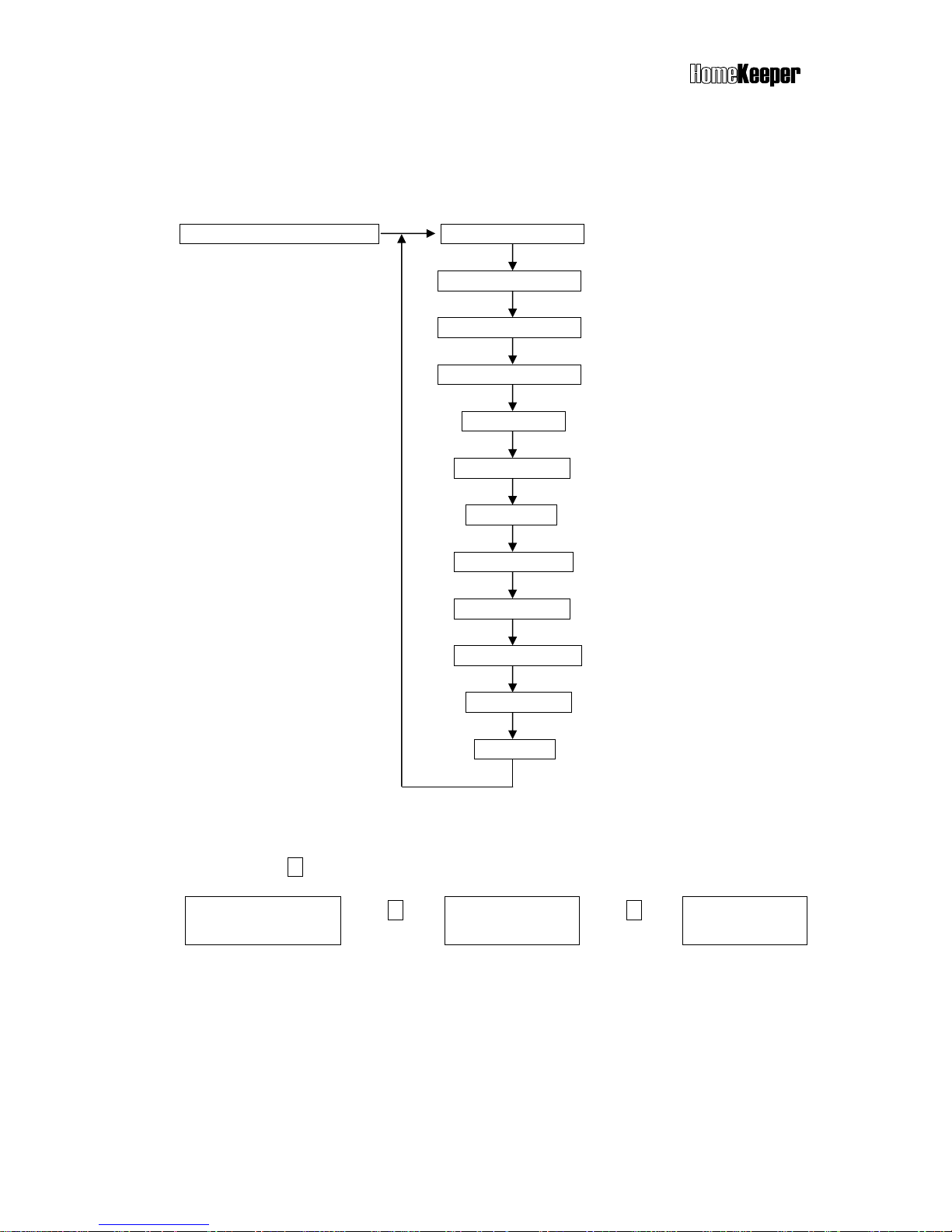
5.3 INITIAL STATE
Once the system is first time powered, the LCD will display SYSTEM RESET and indicate the
time data of power on reset. Operator can key-in “0000DC” to clear the display to clear the
display and enter into the Initial State.
By entering correct code, user can execute System Check, Hot Key control function or
enter into Master, Installer or CMS modes.
Initial State
Master or User Code Other Codes
Hot Hey Enter
Hot Key Process System Check or Hot Key? System Check?
Yes No Yes No
System Check Master Mode Installer Mode CMS Mode
(refer to 5.4) (refer to 5.5) (refer to 5.6) (refer to 5.7)
Hot Key : The following keys allow user to enter into specific operation mode directly.
Enter AWAY Mode.
Enter HOME Mode.
Clear LED/LCD display, reset siren and stop dialing immediately.
Page 12
TM
12
Message in reading (refer to 8.1)
AWAY, HOME & DISARM Modes - refer to the OPERATION MODES
The ARM Mode in this manual means AWAY or HOME Mode.
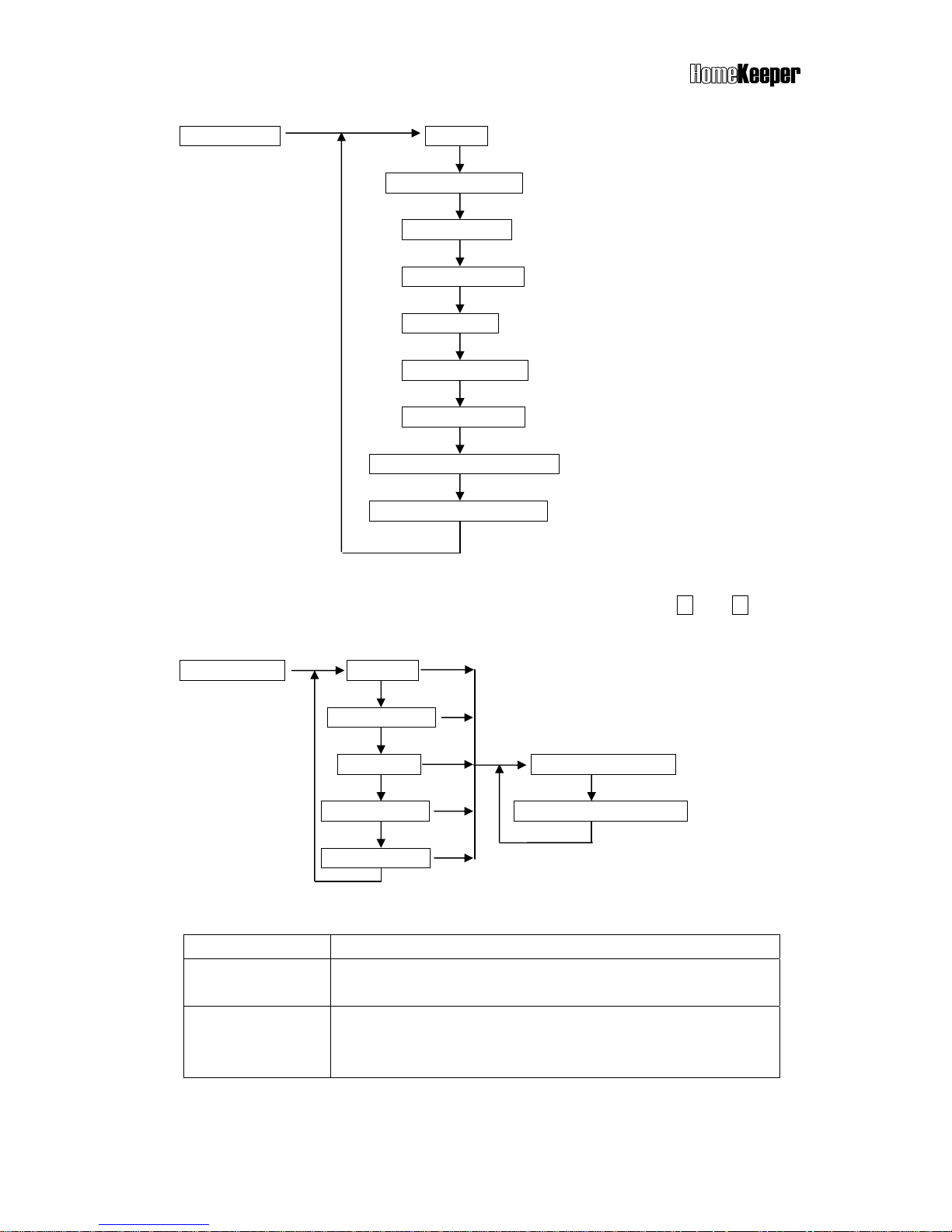
5.4 SYSTEM CHECK
System Check Event Check Check By Sequence
Check By Date
Telephone Number Check (5.4.1)
Voice Check (5.4.2)
Device Check (5.4.3)
5.4.1 Event Check
The Main Controller can store up to 512 system operation events. These events can be
checked either by time sequence or entering the date. Use or key to scroll the
log up or down.
Reading Event Check Display
LCD shows Description
C02-03 Disarm
04/26 22:08 01
Remote Control Keyfob #02-03 disarmed the system
at 22:08 on April 26
th
. 01 means this is the latest event.
B01-02 Burglar
01/02 19:32 253
Burglar Sensor #01-02 reported an alarm signal at
19:32 on January 2
nd
. This is event #253.
Enter DISARM Mode & reset siren.
Enter hands-free Telephone Mode. The Main Controller can be used as
a hands-free telephone for 10 minutes once entering this mode. Press
ESC to disconnect and return to normal operation mode.
X-10 switch control (X-10 switch control module is an optional device).
Close or open the alarm relay terminals on the rear panel.
Open the door (door lock controller is an optional device).
Page 13
TM
13
5.4.2 Telephone Number Check
This operation can verify the telephone numbers stored in the memory and their
answering types. To know the usage of different telephone numbers, please refer to the
section “Setting Telephone Number”.
Telephone Number Check Common 1 Number
Common 2 Number
Common 3 Number
Common 4 Number
Panic Number
Burglar Number
Fire Number
Medical Number
Special Number
Latchkey Number
Pager Number
Pager Data
Reading the Telephone Number Display
If the telephone number is more than 16 digits, it will be displayed in two rows on the
screen. Press key to check the rest part of the number.
Common 1
123456789012345 -
Press
Common 1
- 6789V
Press
Common 2
222222222T
Above example shows the Common 1 telephone no. is 1234567890123456789 and
answered by Voice (V). The Common 2 telephone number no. is 222222222 and
answered by Tone (T).
5.4.3 Voice Check
Voice Check operation allows user to play-back the pre-recorded voice messages
under various conditions. For the usage of different voice messages, please refer to the
section “Set Sound”.
Page 14
TM
14
Voice Check All Voice
Common Segment
Panic Segment
Burglar Segment
Fire Segment
Medical Segment
Special Segment
Latchkey Disarm Segment
Latchkey Away Segment
5.4.4 Device Check
This operation allows user to check the status of all devices. Using and keys to
scroll the display screen up and down.
Device Check Controller
Burglar Sensor
Fire Sensor Check By sequence
Medical Button Check By Zone Number
Special Sensor
Reading the Device Status Display
LCD shows Description
Remote Ctl. 02
C01-02 Normal
Controller #2 is a Remote Control Keyfob. Zone number is
01-02. Status is normal.
Mag. Sensor 07
B10-12 Trouble
Burglar Sensor #7 is a Magnetic Sensor. Zone number is 10-
12. Status is trouble. (Go to System Check-Event Check to
check the trouble)
Page 15
TM
15
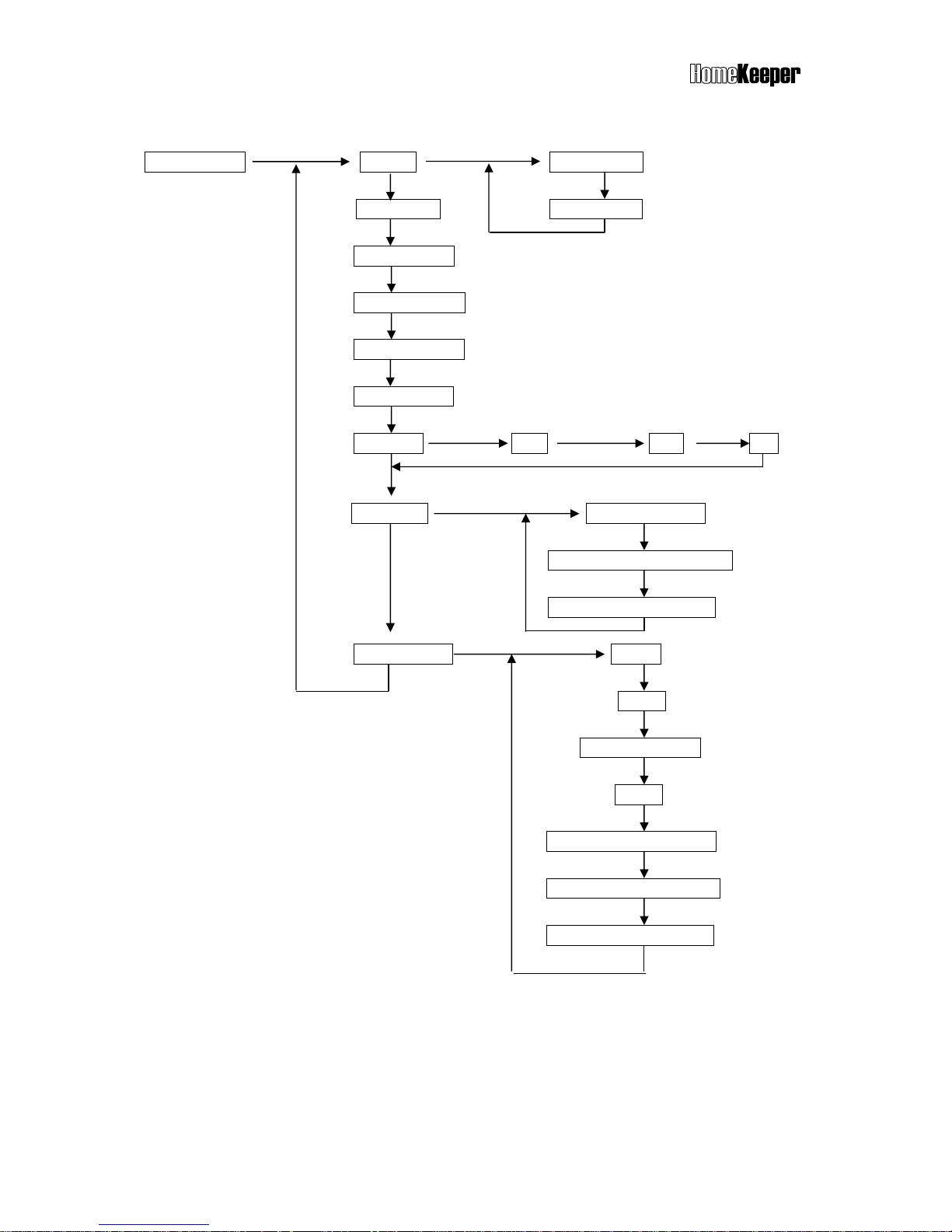
5.5 MASTER MODE
Master Mode Set Bell Door Bell On
Device Test Door Bell Off
Monitor Mode (Only can be entered in Disarm Mode)
Set Partial ARM
Set Entry Delay (Refer to Set Timer- Set Entry Delay)
Set Exit Delay (Refer to Set Timer- Set Exit Delay)
Set Clock Time Date Day
Set Switch Set House Code
Set X-10 SW Auto Control
Set Relay Auto. Control
Set Password Master
User 2
User 3 ~ User 7
User 8
User 9, (Latchkey User)
User10, (Latchkey User)
User 11(Duress Code)
Bell ON/OFF (default ON)
This setting is to enable/disable the door chime output in disarm mode.
Bell ON: The Main Controller will generate a doorbell sound (Ding! Dong!) when Burglar
sensor detects intruder in Disarm mode, if the Bell ON/OFF function is set ON.
Bell OFF: No doorbell chime will sound if the Bell ON/OFF function is set OFF.
Note: This function only works for the Burglar Sensor whose Bell ON/OFF status is set ON
(Refer to 6.4.1Change Device Setting-Burglar Sensor-Enable State-Bell ON/OFF)
Page 16

TM
16
Device Test
The system will initiate a 5-minute test period for user to test the functions of all system
devices (not include Remote Control Keyfob). During device test period, the Main Controller
will only sound beep when it receives signal from any system device. When test period
expired, the system will return to its original mode automatically. The system will escape
from the Device Test mode immediately when it receives Arm/Disarm command signal.
Monitor Mode
The purpose of this mode is to monitor all activities occurred in the designated areas during
Disarm Mode. In monitor mode, any trigger signal from Burglar Sensor (except the sensors
assigned in group 91 ~ 99 Partial Arm Zone) will be recorded only as a trigger signal in the
Event Log, no alarm output will be issued. The system will escape from the Monitor mode
immediately when it receives Arm/Disarm command signal.
Set Partial Arm
Group 91 to 99 are 9 independently protected zones. These zones can be separately
armed/disarmed.
Set Switch
Set House Code <A-P>: (default <A>)
This code should be the same as the House Code set on the X-10 switches, user can
select code from A to P.
Set X-10 SW Auto Control
Set the X-10 switch working schedule for home automation applications. Please refer
to the X-10 device operation instruction.
Set Relay Auto Control
Set the operation schedule of alarm Relay.
Entry Delay: Refer to Installer Mode - Entry Delay.
Exit Delay: Refer to Installer Mode - Exit Delay.
Set Password
Latchkey User
User 9 and User 10 are also called Latchkey Users. The HomeKeeper will dial the
Latchkey Number (Refer to Set Telephone Number- Latchkey Number) when these
users arm or disarm the system.
Duress Code (reserved): This code is used to notify the CMS (Central Monitoring
Station) that a duress situation has occurred and user requires immediate assistance.
This code is normally used under duress condition, while user does not want to alert
the intruder about the fact of calling for help. When duress code is once entered,
Page 17

TM
17
the system will be disarmed and a duress signal will be sent to the CMS
immediately. Once receiving the duress signal, the CMS can response the
situation without contacting the user.
5.6 OPERATION MODES
The HomeKeeper system provides three different protection modes to fulfill different
requirements and situations.
5.6.1 AWAY Mode
When user leaves the protected premises, the AWAY mode is set to provide total
protection. During AWAY mode, the system will generate an alarm condition if Main
Controller receives signal from any sensor that are set on duty.
Set AWAY Mode from Main Controller
To enter the AWAY mode from Main Controller keypad operation, just pressing Hot
Key A and then system will initiate the exit delay. The system will enter into AWAY
mode after the exit delay expired.
Set AWAY mode from Remote Control Keyfob
To enter the AWAY mode from Remote Control Keyfob, just pressing the AWAY
button and then system will enter into the AWAY mode immediately.
Note: Exit delay is a period of adjustable time (0 ~255 seconds) that allows user to
leave the premises without activating the alarm.
Note: If any door or window is left open while setting the HomeKeeper into AWAY
mode, the Main Controller will generate a warning message by showing the zone
number on the LCD display and automatically insert additional 20 seconds Exit Delay
if no Exit Delay has been set. Close the door or window so that the system can enter
into the AWAY mode.
5.6.2. HOME Mode
HOME mode provides the partial protection required by user while staying at home.
Under this operation mode, the HomeKeeper will report an alarm condition if any
HOME mode active Burglar Sensor (ENABLE STATE-HOME MODE-ACTIVE)
detects intruder.
Set HOME Mode from Main Controller
To enter the HOME mode from Main Controller keypad operation, just pressing Hot
Key B and then system will initiate the exit delay. The system will enter into HOME
mode after the exit delay expired.
Page 18

TM
18
Set HOME mode from Remote Control Keyfob
To enter the HOME mode from Remote Control Keyfob, just pressing the HOME
button and then system will enter into the HOME mode immediately.
Note: When you set the HomeKeeper system in Home Mode, the Main Controller will
check the status of all Door/Window Sensors. If any of the sensors is open, the Main
Controller will issue a warning message and display the zone number of opened
sensor on the LCD display for user to check.
5.6.3 DISARM Mode
DISARM mode is normally used when user stays in the premises. During this mode,
the HomeKeeper will not issue any alarm condition by Burglar Sensors, but all 24Hour Zone Sensors, Fire Sensors, Panic and Medical Help Button will still work.
Set DISARM Mode from Main Controller
To enter the DISARM mode from Main Controller keypad operation, just pressing Hot
Key D and then system will initiate the entry delay. The system will enter into DISARM
mode after the entry delay expired.
Set DISARM mode from Remote Control Keyfob
To enter the DISARM mode from Remote Control Keyfob, just pressing the DISARM
button and then system will enter into the DISARM mode immediately.
5.7 ALARM REACTIONS
The HomeKeeper system will react to various alarm and abnormal condition as the following
table shown. Burglar alarm can only be activated when the system is set at HOME or AWAY
mode, while Fire, Panic and Medical alarms can be activated at anytime under any operation
mode. When any of the alarm condition occurs, the Main Controller will dial the designated
number stored to call for help.
Alarm Reaction Table
Note 1: Pressing the buttons on the unit will neither send out the voice message nor trigger
the alarm, despite of being assigned as Panic or Medical.
Burglar Alarm Response
AWAY Mode Entry Delay Burglar Alarm →
↑ (0-255 seconds) ↑
System status: Burglar sensor triggered Siren goes off, dialing---
Page 19

TM
19
TO STOP TELEPHONE DIALING AND SIREN OUTPUT
If necessary, the user can interrupt the telephone dialing and stop the siren output by
disarming the system (entering correct code), and clear the alarm LED/LCD indication by
pressing the Hot Key C
5.8 ANSWERING PHONE CALL FROM HOMEKEEPER
When you receive phone call from HomeKeeper, you can communicate with the system by
operating as follow.
When pick up the phone, your voice on the line will activate the message recorded in
the HomeKeeper for the telephone number assigned as voice acknowledgement.
You will hear the message twice, reporting the alarm event happened to the system.
After the message stop, the HomeKeeper enters the monitoring mode for 60 seconds.
You can hear the sound from your premises via microphone built-in the HomeKeeper or
talk to the people over there.
During the 60-second monitoring mode, you can also remotely control your
Sources &
Reaction
Alarm
Type
Alarm Trigger
Sources
Dialing
Telephone
Numbers
Besides CMS
Voice message
segment
on Telephone
Voice from
the Main
Controller
Siren Status
Burglar
PIR Detector
Door/window
sensor
Glass Break
Detector
Pager+ Burglar+
Common 1- 4
Sequentially
Burglar &
Common
Silent Programmable
Fire
Smoke Detector
Gas Detector
Pager+ Fire+
Common 1- 4
Sequentially
Fire &
Common
Play Fire
Message,
Programmable
Programmable
Panic
Panic Button of
Remote Control
Keyfob
Wireless Keypad
Pager+ Panic+
Common 1- 4
Sequentially
Panic &
Common
Silent
Programmable
Medical
Wireless Medical
Button
Medical Button on
the Main Controller
Pager+ Medical
+ Common 1-4
Sequentially
Medical &
Common
Play Medical
Message,
Programmable
Programmable
Special
Temperature
Sensor
Humidity Sensor
Flood Detector
Pager+ Special
+ Common 1-4
Sequentially
Special &
Common
Silent Programmable
Disarmed Mode
NO NO Silent Programmable
Tamper
Main Controller
PIR Detector
Door Sensor
Glass Break
Detector
Wireless Keypad
Armed Mode
Same As Burglar Alarm
Low Battery
PIR Detector
Door Sensor
Glass Break
Detector
Smoke Detector
Wireless Medical
Help Button
Other Sensors
NO
NO
Silent
OFF
Page 20

TM
20
HomeKeeper via local telephone keypad operation.
Press 0 : Disconnect the HomeKeeper immediately. Stop dialing and siren.
Press 1 : Disconnect the HomeKeeper immediately. Dial the next number.
Press 3 : Enter into speak-only mode. (The microphone of HK-MC868 is disabled.)
Press 5 : Enable 2-way hand-free speaker communication.
Press 8 : Enable listen-only monitoring
Press any other key: Extend the connection for another 60 seconds.
Note: The sound of siren or background noise may affect the decoding of remote control key
tone input, so keep pressing the key until the command is accepted.
Note: If the phone number requires a DTMF tone acknowledgment, remember to press a key
on the telephone keypad while answering the call from the HomeKeeper to prevent it
redialing the number again.
Answering Sequence
HomeKeeper Voice Message Monitoring &
Dialing Playback Communication
Twice for 60 seconds
Ring!---Ring!
Answered by voice (“hello”)
or press a DTMF key
5.9 DIAL-IN CONTROL
Dial-in Control means that you can control and check status of your HomeKeeper via a
phone anywhere in the world. This function is available if auto-answer function (refer to
(4-2) Set Telephone – Set Auto Answer) and ring count number are both set.
Note: If you connect a fax machine or answering machine on the same telephone line,
please refer to their manuals and Section 8.7 to avoid any improper operation.
Note: The ring count number should be set more than 3, otherwise, the telephone line noise
0 : Disconnect and stop further dialing & siren.
1 : Disconnect and dial the next number.
3 : Enter into speaker-only mode.
5 : Enable 2-way speaker communication.
8 : Enable listen-only monitoring.
X : Press any other key to extend connection for
Page 21

TM
21
may activate the dial-in control sequence. Pulse dial phone cannot control the HomeKeeper
system.
To operate dial-in control function, please proceed as follows:
1. Dial the telephone number of which the HomeKeeper is connected.
2. After the preset ring count number, you will hear the beeps.
3. Key in the password (start with
* and end with # ) from local telephone keypad within
30 seconds. If the password is correct and well received, you will hear beeps again. If
not, please enter the password again.
4. After entering the valid password, the HomeKeeper will switch to the monitoring mode
for 60 seconds. During this period, you can enter commands from the local telephone
keypad to control the HomeKeeper.
* 0 : Disarm the system (echoed by beeps) after exit Dial-in Control.
* 1 : Arm the system in Home Mode (echoed by beeps) after exit Dial-in Control.
* 2 : Arm the LS-30 in Away Mode (echoed by beeps) after exit Dial-in Control.
* 3 : Enter into speaker-only mode.
* 4 : Check alarm event and system operation mode (echoed by voice)
* 5 : Enable 2-way speakerphone/monitoring only (echoed by beeps).
* 6 X X 1 : Turn the X-10 switch no. XX ON X X = number from 01-16.
* 6 X X 0 : Turn the X-10 switch no. XX OFF X X = number from 01-16.
* 7 1 : Switch the Relay ON.
* 7 0 : Switch the Relay OFF.
* 8 : Enter into listen-only monitoring.
* 9 : Disconnect the line immediately.
Press any other key to extend the monitoring period for another 60 seconds.
The Process of Dial-in Control
Dial Phone Number Enter Password
in 30 seconds 60 sec. monitoring
Ring count as user set *XXXX# Ready for key tone command
Page 22

TM
22
6. INSTALLER SETTINGS
The Installer Mode allows installer to set all system setting. To make the complicated system
setting work easier and faster, manufacturer suggests installer to program all settings via
HyperSecureLink, although all settings can still be done via keypad operations on the Main
Controller.
The following chart shows all settings of installer mode. Individual setting procedure is
described in the following sections.
Enter Installer Password
Installer Mode Set Timer (6.1)
Set Telephone (6.2)
Set Sound (6.3)
Set Device (6.4)
Set Siren (6.5)
Set Misc. (6.6)
Set GSM (6.7)
6.1 Timer Settings
Set Timer Set Entry Delay
Set Exit Delay
Set Inner Siren Time
Set Relay Action Time
Set Sensor Supervise Time Unit In Second
Set Remote Siren Time Unit In Minute
Page 23

TM
23
6.1.1 Entry Delay for Burglar Sensor : 0 ~ 255 seconds (default 0 sec.)
Entry Delay is the time given for user to disarm the system before alarm goes off. Once
the door is opened during AWAY mode, the HomeKeeper will issue warning beeps (if
the Entry Delay Beep is set On) to remind user to disarm the system immediately.
Note: To set the Entry Delay Beep, please refer to 6.3 Set Sound - Entry Delay Beep.
AWAY Mode Entry Delay Burglar Alarm →
↑ (0-255 seconds) ↑
System status: Burglar sensor triggered Siren goes off, dialing--This Delay only operates on the Burglar Sensors if its Delay ON/OFF setting is set ON.
Please refer to 6.4.1 Change Device Setting - Burglar Sensor - Enable State - Delay
ON/OFF.
6.1.2 Exit Delay for Controller : 0 ~ 255 seconds (default 0 sec.)
Exit Delay is the time given for user to leave the premises before the AWAY mode is
effective. During this delay, the HomeKeeper will issue warning beeps to remind the
users to leave the premises as soon as possible.
Note: Since the Door Open signal may last for 10 seconds, so add 10 seconds to the
time you need to leave the house as the Exit Delay. (Ex. you need 20 seconds to leave
the house, set Exit Delay=30s)
Disarm Exit Delay AWAY mode effective →
↑ beep! (0-255 seconds)
System status: Set AWAY mode
This Delay only works on the Controller if its Delay ON/OFF setting is set ON. Please
refer to 6.4.1 Change Device Setting – Controller - Enable State-Delay ON/OFF.
6.1.3 Internal Siren Time Setting : 0 ~ 255 seconds (default 60 sec.)
Setting the output time of internal siren of HomeKeeper while alarm goes off.
6.1.4 Relay Activation Time Setting : 0 ~ 120 minutes (default 60 sec.)
Setting the activation time of alarm relay of HomeKeeper while alarm goes off.
6.1.5 Sensor Supervised Time Setting : 0 ~ 24 Hours (default 4 Hours)
The HomeKeeper is a supervised wireless alarm system, meaning certain Burglar
sensors will send “heartbeat” signals to the Main Controller at a certain period of time.
If the Main Controller does not receive RF heartbeat signal from a specific sensor
within the supervised time, the HomeKeeper will consider this sensor out of function
and therefore issue a warning message for the attention of system operator.
Page 24

TM
24
Note: The sensor supervised time can be set from 0 to 24 hours. Setting 0 means the
system will NOT check for the “heartbeat” signal from sensor).
6.1.6 External Siren Time Setting : 0 seconds to 30 minutes (default 1 minute)
Setting the output time of wireless external siren while alarm goes off. (External Siren is
an optional device.)
6.2 Telephone Settings
Set Telephone Set Telephone Number (6.2.1)
Set Dial Mode Tone
Pulse 33/66
Pulse 40/60
Set Auto Answer Auto Answer On Set Ring Count
Auto Answer Off
Set Telephone Line Cut Detection Permanent Off
Away Mode On
Permanent On
Set Cease Dialing Mode 30 Minutes Due
CMS Report OK
Set Tel. Ringer Tel. Ringer On
Tel. Ringer Off
Set Dial Tone Check Dial Tone Check Enable
Dial Tone Check Disable
Set Tel/GSM Link
Page 25

TM
25
The HomeKeeper system can be linked with local PSTN telephone system to provide many
remote control/indication functions. To ensure proper operation of all these functions, please
refer to the following contents for correct settings.
Dial Mode: Tone, Pulse 33/66, Pulse 40/60 (default, Tone)
Check the local telephone system and select the proper Pulse or Tone mode for auto-dialer.
Auto-Answer Ring Count: Auto-Answer ON Ring Count 1-30, Auto-Answer OFF (default,
Auto-Answer OFF)
Auto-Answer ON: The Main Controller will automatically answer the incoming call
when the set ring count number is reached.
Auto-Answer OFF: The Main Controller will not answer the incoming call.
Note: To use dial-in control, the Auto-Answer has to be set “ON”. Three or more ring
counts are recommended to avoid triggering by noise.)
Telephone Line Cut Detection: Permanent OFF, Away Mode ON, Permanent ON
(default, Permanent OFF)
The HomeKeeper can be set to check the telephone line. If the phone line is cut and this
function is set “ON”, the internal siren will go off (the internal siren has to be set “ON”) to
alert the user.
Permanent OFF: The system will NOT check the telephone line connection.
Away Mode ON: The system will check the line status only in AWAY mode.
Permanent ON: The system will check the telephone line status at all time.
Cease Dialing Mode: 30 Minutes, CMS Report OK (default, 30 Minutes)
30 Minutes: The auto-dialer will stop dialing 30 minutes after alarm condition or all
the stored telephone numbers have been dialed 10 times without a successful
connection.
CMS Report OK: The auto-dialer will stop dialing after the report to CMS is
successful.
Note: The Latchkey number will still be dialed when the Latchkey Controller
Arms/Disarms the system or the detection of Power Loss/Restore event, even this
status is set as “CMS Report OK”.
Tel. Ring: ON, OFF (default, OFF)
Tel. Ring ON: Activate the incoming call ring.
Tel. Ring OFF: Deactivate the incoming call ring.
Dial Tone Check: Enable, Disable (default, Enable)
Dial Tone Check Enable: The auto-dialer will wait for the dial tone before dialing.
Dial Tone Check Disable: The auto-dialer will not wait for the dial tone before
dialing.
Page 26

TM
26
Tel/GSM Link: (default, Tel.)
Tel. Link: Report the alarm condition from PSTN telephone line.
GSM Link: Report the alarm condition from GSM module.
Note: If GSM link is used, refer to (6-7) Set GSM to set all the parameters needed for
GSM communication and APPENDIX A-6 for GSM connection set up.
.
Setting Telephone Numbers
Set Telephone Number Common 1 Number
Common 2 Number
Common 3 Number
Common 4 Number
Panic Number Answer By Voice
Burglar Number Answer By Tone
Fire Number
Medical Number
Special Number
Latchkey Number
Pager Number
Pager Data
6.2.1 Telephone Number Setting
The HomeKeeper system can store up to 10 telephone and 1 pager numbers (each up
to 23 digits) for auto-dialer function.
4 common numbers and 1 pager number
These numbers will be dialed at all types of alarm condition as the alarm reaction table
(section 5.7) shown. These can be telephone numbers of office, friends, neighbors or
families.
Page 27

TM
27
5 specific numbers for different alarm condition
These 5 numbers (Panic, Burglar, Fire, Medical, Special) will be dialed under different
alarm condition respectively.
Latchkey number (Password status report number)
This number has two functions.
1) When a Latchkey Remote Control Keyfob (refer to 6-4-1 Change Device Setting-
Enable State-Latchkey) or any user arms the system in “AWAY” mode or disarm
the system with Latchkey password (User 9 & 10 password). This function can be
used to inform the parents that their children are home. Normally, the Latchkey
number is parent’s mobile phone number.
2) When Main Controller detects AC power failure or restore, this number will be
dialed after a random delay of 30 ~ 120 seconds. The pre-recorded message
(power loss/power restore) will be played when call is connected.
Pause Insertion
Use Pause key
to insert pauses between telephone number digits for dialing
to a PABX extension number. Each pause creates a 3-second break.
Answering status: Voice, Tone (default, Voice).
After dialing, the HomeKeeper requires an acknowledgement from the called party,
either by voice like “Hello” or by a DTMF key tone to ensure the call is connected
successfully. Without proper acknowledgement, the call will be deemed to have failed
and will be redialed in the next cycle.
Alarm Report Dialing Sequence
CMS1→CMS2→SMS1---->SMS5→Pager→ Specific alarm number → 1st to 4th
Common numbers.
If there is any number that cannot be connected successfully, the auto-dialer will skip
to the next one and try again in the next cycle until all the numbers have been tried 10
times or the cease dialing condition has been reached. (Refer to (6-2) Set Telephone
- Set Cease Dialing Mode.)
Note: CMS1 and CMS2 are Central Monitoring Station numbers. SMS1 and SMS5 are
mobile phone SMS (Short Message Service) and only valid for the system with
GSM module.
Page 28

TM
28
6.3 Sound Setting
Set Sound Record Voice Common Segment 13 Seconds Record
Panic Segment 4 Seconds Record
Burglar Segment 4 Seconds Record
Fire Segment 4 Seconds Record
Medical Segment 4 Seconds Record
Special Segment 4 Seconds Record
Latchkey Disarm 4 Seconds Record
Latchkey Away 4 Seconds Record
Voice Check (Same as 5.4.3)
Set Entry Delay Beep Delay Beep On
Delay Beep Off
Record Voice: When an alarm call is successfully connected, the HomeKeeper will play the
voice message pre-recorded of which corresponds to the alarm type.
Different message should be recorded at specified segment.
Common Segment (13 seconds): The voice for playback at all alarm conditions.
This segment should contain user’s name, address and telephone number.
Ex: “This is ---, I live at---, phone number is---.”
Panic Segment (4 seconds): The voice for playback at Panic alarm.
Ex: “Break-in! Break-in! Calling for emergency help.”
Burglar Segment (4 seconds): The voice for playback at Burglar alarm.
Ex: “Burglar! Burglar! Calling for emergency help.”
Fire Segment (4 seconds): The voice for playback at Fire alarm.
Ex: “Fire! Fire! Calling for emergency help.”
Medical Segment (4 seconds): The voice for playback at Medical alarm.
Ex: “Heart patient! Calling for emergency help.”
Special Segment (4 seconds): The voice for playback at Special alarm.
Ex: “High temperature in the building! Calling for an alert.”
Latchkey Disarm (4 seconds): The voice for playback when a latchkey user disarm
the system.
Ex: “I’m home.”
Page 29

TM
29
Latchkey Away (4 seconds): The voice for playback when a latchkey user set the
system in AWAY mode.
Ex: “I’m out.”
Entry Delay Beep: ON, OFF (default, OFF )
Entry Delay Beep ON: The Main Controller will generate beeps during the Entry
Delay and the beeping speed will get faster while approaching the end of the delay
time.
Entry Delay Beep OFF: No beeps during the Entry Delay.
6.4 System Device Setting (Enrolling Wireless System Device)
Set Device Enroll Device Controller Enroll
Burglar Sensor Enroll
Fire Sensor Enroll Zone Number
Medical Button Enroll
Special Sensor Enroll
Change Device Setting (6.4.1)
Delete Device Controller Delete
Burglar Sensor Delete
Fire Sensor Delete Zone Number
Medical Button Delete
Special Sensor Delete
Special Sensor Limit Set Enter Zone Number High Limit
Wire Sensor Assignment Select Input Low Limit
Select Type Enable State
Enroll Device: The HomeKeeper utilizes a state-of-the-art radio coding technology to
provide maximum reliability of system operation. This technology enables the Main
Controller to identify its system devices by their unique ID codes. Therefore, the Main
Controller has to learn the ID codes of all system devices while installing the system.
Page 30

TM
30
Note: Each sensor has its own unique ID that is preset in the factory.
60 seconds for Device Enroll
After initiating the Enroll Device procedure, there is a 60-second time window for
the device to transmit an RF signal to complete the code learning.
Delete Device: Remove device from the system.
Special Sensor Limit Set: Set High/Low setback limits for special sensor, such as
temperature sensor and humidity sensor.
Wire Sensor Assignment: Set the parameters for the wired type sensor inputs from the rear
panel. Up to three wired sensors can be assigned. The wired sensor input can accept either
normally closed (N.C.) or normally open(N.O.) signal.
Note: The zone numbers of the wired sensors are fixed as “00-01”, “00-02” and “00-03”.
6.4.1 Changing Device Setting
Change Device Setting Controller Change
Burglar Sensor Change Enter Zone Number
Fire Sensor Change Enable State
Medical Button Change Zone Number
Special Sensor Change Switch Control
Enable Device State
This setting changes the response of HomeKeeper system from various system devices.
Device On Duty, Bypass (default On Duty):
Device On Duty: This sensor is working in the system.
Device Bypass: Bypass this sensor, the system will ignore the alarm signal
transmitted from this sensor.
Note: This setting is available for all system devices.
Delay ON, OFF (default Delay OFF):
Delay ON: (Refer to 6.1 Set Timer - Exit Delay/Entry Delay.)
For the Remote Control Keyfob, the Exit Delay will be imposed on the AWAY
command from this controller.
For the Burglar sensor, the Entry Delay will be imposed on the Burglar alarm signal
from this sensor.
Page 31

TM
31
Delay OFF: The trigger signal or command from this sensor or controller will be
processed immediately regardless of the Exit/Entry Delay setting.
Note: This setting is available for Remote Control Keyfob & Burglar sensors only.
24-Hour Zone YES, NO (default 24-Hour Zone NO):
24-Hour Zone YES: Alarm signal from this Burglar sensor will be processed at all
time regardless of the system operation mode, either in Arm or Disarm.
24-Hour Zone NO: The alarm signal from this Burglar sensor will only be processed
during AWAY or HOME mode.
Note: This setting is available for Burglar sensor only.
Home Mode Active, Inactive (default PIR Inactive, Door/Window sensor Active)
Home Mode Active: This Burglar sensor will trigger the alarm condition during
HOME mode.
Home Mode Inactive: This Burglar sensor will NOT trigger the alarm condition
during HOME mode.
Note: This setting is available for Burglar sensor only.
Voice Warn ON, OFF (default Voice Warn ON)
Voice Warn ON: If this sensor sends an alarm signal, there will be a 30-second
voice warning from the Base Unit before the alarm reaction procedure starts.
Voice Warn OFF: There is no voice warning. The Base Unit responds immediately
when there is an alarm issued by this device.
Note: This setting is available for Fire sensor & Medical Help Activator.
Siren/Relay ON, OFF (default Siren/Relay ON, only OFF for Controller)
Siren/Relay ON: The alarm relay and sirens (both Internal Siren and External Siren)
will be activated when an alarm condition is issued by this device after the Delay
time or Voice Warning ended.
Siren/Relay OFF: The alarm relay and sirens will NOT be activated when an alarm
condition is issued by this device.
Note: This setting is available for all system devices.
Bell ON, OFF (default Bell OFF)
Bell ON: The Main Controller will generate a doorbell chime when it receives a
trigger signal from this sensor during disarm mode, if the Bell status is set ON in
Master Mode (Refer to (3) Master Mode - Bell Check - Door Bell.)
Bell OFF: No doorbell chime will be generated when receiving a trigger signal from
this sensor during disarm mode.
Note: This setting is available for Burglar Sensors only.
Latchkey ON, OFF (default Latchkey OFF)
Latchkey ON: This Remote Control Keyfob is assigned as a Latchkey Remote
Control Keyfob. (Refer to (6-2-1) Set Telephone Number - Latchkey Number.)
Page 32

TM
32
Latchkey OFF: No Latchkey number will be dialed if using this Remote Control
Keyfob to disarm the system.
Note: This setting is available for Remote Control Keyfob only. not for the
Controllers assigned in Group number 91-99 Partial Arm Zones
Inactivity ON, OFF (default Inactivity OFF)
Inactivity ON: This Burglar Sensor is assigned as an Inactivity Sensor (no longer a
Burglar Sensor) to monitor the activity of the elderly or physically disabled person in
the protected area. If there has been no activity detected during the preset Inactivity
Time, (Refer to 6.6 Set Misc.-Set Inactivity) an Inactivity Alarm (medical) will be
issued.
Inactivity OFF: This is a normal Burglar Sensor.
Note: This setting is available for Burglar Sensors only.
Supervision ON, OFF:
(Refer to (4-1) Set Timer - Sensor Supervised Time.)
Supervision ON: System will check the “heartbeat” signal from this sensor.
Supervision OFF: System will NOT check the “heartbeat” signal from this sensor.
Type Alarm, Control (default Type Alarm): (For Special Sensor)
To assign the Special Sensor as an Alarm Device or a Control Device.
(Refer to the manual of the Special Sensor.)
Note: This setting is available for Special Sensor only.
Operation Low, High (default Operation Low): (For Special Sensor)
To set the switches or the relay operation when the reading of Special Sensor
reaches the low limit or high limit setback.
(Refer to the manual of the Special Sensor.)
Note: This setting is available for Special Sensor only.
Switch control: Select the switches that will be activated when this sensor is triggered.
X-10 Switch
Up to 16 pieces of X-10 switch (optional) can be controlled by the HomeKeeper. To set
the X-10 device, please refer to the instructions of the X-10 switch.
Note: If pressing the DISARM button of Remote Control Keyfob in DISARM Mode, the
X-10 switches assigned as active will be turned ON or OFF.
Page 33

TM
33
6.5 Siren Setting
Set Siren Set Inner Siren Inner Siren On
Inner Siren Off
Set Mode Change Chirp Mode Chirp On
Mode Chirp Off
Set Tamper Siren In Disarm Siren On
Siren Off
Set Remote Siren Type Standard Series
HA Series ID Number Change
Siren/Relay Test Start Test
Inner Siren ON, OFF (default ON)
This setting enables/disables the operation of the built-in siren.
Inner Siren On: Enabling the siren.
Inner Siren Off: Switch off the siren. (The siren will remain silent in alarm condition)
The conditions for the Inner Siren to go off when alarm occurs:
1. The Inner Siren is normal.
2. The siren ON/OFF state of the sensor triggering the alarm is set “ON”.
3. The Inner Siren Time has not been set “0”.
Mode Change Chirp: ON, OFF (default OFF)
Mode Change Chirp On: The siren will sound short chirp (disregard the inner siren
status) while the operation mode changes. (Disarm: 1 chirp, Away: 2 chirps, Door
open warning: 5 chirps).
Mode Change Chirp Off: The siren will remain silent while the operation mode
changes.
Tamper Siren In Disarm: ON, OFF (default OFF)
Tamper Switch
A Tamper Switch is built-in the Main Controller to prevent unauthorized removal of
the device. This switch will be closed by a cam when the Main Controller is attached
to the Mounting Bracket. The switch will be activated if someone detaches the Main
Controller from the Mounting Bracket.
Page 34

TM
34
Tamper Siren In Disarm On: The siren will go off (internal siren is enabled) if someone
detaches the Main Controller from the Mounting Bracket or triggers the Tamper Switch
on the Main Controller or sensors during Disarm Mode.
Tamper Siren In Disarm Off: The siren will NOT go off if the Main Controller is removed
from the Mounting Bracket or receiving the tamper signal from sensors during Disarm
Mode.
Set Remote Siren Type: Select the type of the external siren used in the system.
(reserved)
Siren/Relay Test: This test will activate the Internal Siren, close the Relay contacts and
send an Activated signal to the External Siren (if installed) immediately regardless of the
Internal Siren status.
6.6 Miscellaneous Setting
Set Misc. Set RF Jamming Warning
Check ROM Version
Reset To Factory Default Enter to Reconfirm
Emergency Button Assignment
Set Inactivity Inactivity ON Inactivity Time
Set Password Inactivity OFF
Set RS-232 Control
RF Jamming Warning: (default OFF)
Enable or disable the RF jamming warning.
Reset To Factory Default:
Reset all system settings to factory default when necessary.
Emergency Button Assignment: Panic / Medical (default Panic)
Select the function of the Emergency Button as a Panic Button or a Medical
Help Activator (with the zone number of 00-05).
Set Inactivity: ON, OFF (default OFF)
Inactivity On with time (0-72 hours):
1, Respond the inactivity signal from the Medical Help Activator as Medical Alarm.
2, If no activity has been detected during the period from any Inactivity Sensor
(Refer to 6.4.1 Change Device Setting-Burglar Sensor-Enable State-Inactivity)
the system will issue an Inactivity Medical Alarm with zone number 00-06.
Page 35

TM
35
Inactivity Off: Ignore the Inactivity signal from the Medical Help Activator.
Set Password: (default “1234”) Set the Installer Password.
Set RS-232 Control: (default Enable)
Control Enable: The RS-232 interface is available for user to access the system.
Control Disable: The RS-232 interface is disabled.
6.7 GSM Setting
Set GSM Display RSSI
Set GSM Number SMS Number 1(Mobile phone number)
SMS Number 5 (Mobile phone number)
GSM Number
GSM PIN
This setting is only available for the system with GSM Module installed and the
Tel/GSM Link is set as Link=GSM. (Refer to 6.2 Set Telephone- Set Tel/GSM Link)
Display RSSI (Received Signal Strength Indication)
To display the GSM signal strength where the GSM module is located. Try to find a
place where with the best signal reading.
Note: The reading is displayed in dBm. Ex. –50dBm means better signal than –60dBm.
SMS Number 1 ~ SMS Number 5
These 5 mobile phone numbers are due to receive the SMS alarm message from the
system if any alarm condition occurred.
GSM Number
This is the GSM number of the SIM card of the GSM module installed.
Note: When purchased or subscribed the GSM service from service provider, you shall
receive a SIM card and its respective number. This SIM card must be inserted into the
SIM card holder on the GSM module.
PIN Number: The PIN number of the SIM card.
Note: To change the PIN number, please insert the SIM card to a general mobile phone
and change the PIN number accordingly. The GSM module can’t change the PIN
number.
SMS Alarm Message
The system will send SMS message to the SMS Number that has been set in the
system with alarm type, zone number, time, date and GSM Number.
Ex. Burglar 01-03 11:30 12/01/04 0933123456.
Page 36

TM
36
Note: The RF signal (max. 2W) from GSM module may induce noise to the audio circuit of the
Main Controller nearby. After finding the place for GSM module, please make a test
call from the Main Controller and listen to the audio carefully. If you can hear the
humming noise, please relocate the GSM module and the antenna to the place with
less or no noise.
7. CMS SETTINGS
CMS Mode Set CMS1
Set Mode Change Report Report On
Set CMS2
Report Off
Auto Link Check Auto Link Check On Check Interval
Auto Link Check Off
Loopback Test Start Test
Set Telephone Number Telephone Number
Account Number
Set Password
(CMS1 only)
Set CMS Report Report All
Report One
Mode Change Report: ON, OFF (default OFF)
Mode Change Report On
The system will report to the CMS whenever the operation mode (Away/Home/Disarm)
is changed.
Mode Change Report Off
The system will report to the CMS only with alarm condition and warning event, but not
operation mode change.
Auto Link Check: ON, OFF (default OFF)
Auto Link Check On: The system will send a check signal to the CMS periodically.
according to the Interval setting.
Auto Link Check Off: Disable the Auto Link Check function with the CMS.
Loopback Test: The system will send a check signal to the CMS immediately.
Page 37

TM
37
2 Way Audio: ON, OFF (default OFF)
2 Way Audio ON: The Main Controller will enter into 2-way voice communication
mode after sending the alarm report to the CMS.
Note: This function only works for a CMS with Contact ID protocol and has voice
communication capability.
DTMF Data Time: 50ms, 100ms (default 50ms)
Select the DTMF data pulse time as 50ms or 100ms for Contact ID protocol.
Note: Consult with your CMS provider before changing this parameter.
Set CMS Telephone numbers and account number:
Set the telephone number (max. 16 digits) and the user’s account number (max. 8 digits)
of the CMS station.
Set CMS Report: (Only in the CMS1 settings, default Report ALL)
Report All: Report to all CMS numbers/ link set in CMS1, CMS2 and Ethernet Adapter.
Report One: Stop further CMS report if any one of the report succeeds.
8. EXTERNAL CONNECTIONS
8.1 Remote Message Display
User or CMS can send messages via HyperSecureLink to the HomeKeeper if the Main
Controller is connected with Internet through Ethernet Adaptor (optional). The LCD display
will show “Messages Come In” and issue a warning voice periodically to remind the user, if
any new message is received. The user can check the message by pressing 5 after entering
the password during Disarm Mode.
Up to ten 32-character messages with time tag can be stored in the memory of the Main
Controller. To stop the message warning voice, pressing (Hot Key) C after entering the
password.
Note: ! and & can NOT be used in the message.
8.2 RS-232 Computer Interface Connection
COM1 cable USB or RS-232 Adaptor HyperSecureLink Software
To PC
COM Port
To COM1
DC 12V
DRY +12V
CONTACT O/P
COM1
COM2
GNDIN
+12V +
DC ALARM AUX
OUT
AUX
IN
SENSOR
OUT
212
1
-
PHONE
TEL.LINE
AUX
Audio
ALARM OUT
SELECTOR
Page 38

TM
38
DC 12V
DRY +12V
CONTACT O/P
COM1
COM2
GNDIN
+12V +
DC ALARM AUX
OUT
AUX
IN
SENSOR
OUT
212
1
-
PHONE
TEL.LINE
AUX
Audio
ALARM OUT
SELECTOR
DC 12V
DRY +12V
CONTACT O/P
COM1
COM2
GNDIN
+12V +
DC ALARM AUX
OUT
AUX
IN
SENSOR
OUT
212
1
-
PHONE
TEL.LINE
AUX
Audio
ALARM OUT
SELECTOR
Note: If a serial COM port is not available on your PC, you can use a USB to COM Port
Adaptor to connect with your computer.
8.3 Ethernet Adaptor and Internet Remote Access Connection
COM1 Cable Ethernet Adaptor Router
8.4 X-10 Power Line Interface Connection
X-10 Appliance Module X-10 power Line Interface Controller X-10 Cable
8.5 Terminal Block Connection
_
+
HyperSecureLink or
CMS polling software
Internet
To
COM1
Power Line
To COM2
Wired
Sensor 1
Wired
Sensor 2
Arm LED
Indicator
Wired
Sensor 3
Wired Siren
Page 39

TM
39
DC 12V
DRY +12V
CONTACT O/P
COM1
COM2
GNDIN
+12V +
DC ALARM AUX
OUT
AUX
IN
SENSOR
OUT
212
1
-
PHONE
TEL.LINE
AUX
Audio
ALARM OUT
SELECTOR
DC 12V
DRY +12V
CONTACT O/P
COM1
COM2
GNDIN
+12V +
DC ALARM AUX
OUT
AUX
IN
SENSOR
OUT
212
1
-
PHONE
TEL.LINE
AUX
Audio
ALARM OUT
SELECTOR
+ 12V DC This terminal provides max. 200 mA, 12V power for auxiliary devices.
ALARM OUT These two terminals are alarm output contacts. They can be selected as
“dry contact” or “+12V/GND” output from the ALARM OUT SELECTOR
switch.
SENSOR INPUT These three terminals, AUX 1 (Wired Sensor 1), AUX 2 (Wired Sensor 2)
and SENSOR IN (Wired Sensor 3), can accept NO/NC wired type sensor
input. Please refer to 6.4 Set Device-Wire Sensor Assignment for
setting these three sensor inputs.
AUX OUT 2 This terminal indicates the status of system operation mode. Once the
system is armed (AWAY & HOME Mode), this terminal will provide +5V
voltage (with 2 KΩ resistor protected) output, user can connect a LED
display to indicate system mode remotely.
8.6 GSM Module Connection
GSM Antenna GSM Module
Note: Do NOT forget to insert SIM card into GSM Module before connection.
8.7 Connecting HomeKeeper with Phone/FAX/Answering Machine
To Phone
To COM1
COM1 Cable
Audio Cable
To AUX Audio
PSTN Line
Page 40

TM
40
Fax TAM Phone set
The HomeKeeper, Fax Machine and TAM can be connected to the same telephone line and
all these devices can still accept their own dial-in control signal.
1. The auto answering ring counts (Refer to 6.2 Set Telephone-Set Auto Answer) should
be set as:
HomeKeeper ring count> Fax ring count >TAM ring count.
Ex. The ring count of HomeKeeper is 8, ring count of Fax is 6 and ring count of TAM is 4.
2. Set the operation mode of the Fax machine in TAM mode. (Please refer to the manual of
the Fax machine.)
3. When you dial in, the TAM will connect first.
If you want to record a message on the TAM, just do it now.
If you want to send a Fax, just press the TRANSMIT button on the Fax machine.
If you want to control the HomeKeeper system, after the announcement from the
TAM is over (or the Fax tone from the Fax machine is over) then key in the
password, the HomeKeeper will take control of the telephone line.
Note: Line Cut Detection function should be disabled, (refer to 6.2 Set Telephone-Set
Telephone Line Cut Detection-Permanent Off) otherwise the HomeKeeper will
trigger the line cut detection alarm when the telephone line is taken control by the
TAM or Fax.
8.8 Partial Arm for Group Numbers “91” to “99”
The Group Numbers from “91” to “99” are partial arming zones. They can be controlled by a
Remote Control Keyfob, the Panel keyboard or through the HyperSecureLink software
individually. They are independent from the main groups (Group Number “01”~”89”).
The Remote Control Keyfob with Group Number ”9X” only controls the corresponding
burglar sensors with the same Group Number ”9X”. For example, Remote Control Keyfob
with Group Number “91” only controls (Away, Home, Disarm) the burglar sensors with the
Group Number “91”.
When the HK-MC868 receives an AWAY/HOME/DISARM signal from the Remote Control
Keyfob of Group Number “9X”, the HK-MC868 will announce the Away/Home/Disarm
operation with Group Number, but the LCD and LEDs (Green, Red and Yellow) will only
follow the status of the main groups (Group number ” 01”~”89”), unaffected by the status of
Group Number “91”~”99”.
Page 41

TM
41
9. SPECIFICATIONS
Power supply 12VDC, 300mA regulated or 15 VDC >300mA unregulated
Current drain 60 ~ 90mA, subject to the receiver type and rechargeable battery
Radio frequency 868 MHz
Radio modulation Narrow-band FM or OOK
RF output power Less than 10 mW
RF Range About 200 ft. or more at open field @ 25℃
Receiver type Super heterodyne
Radio code 16,777,216 combinations with check sum for each type of sensor
Dial type Pulse/Tone selectable
Dial-out phone no. 10 phone numbers, one pager, 2 CMS data links
Voice message 120 seconds in total
Event log Maximum 512 records
Status display 3 LEDs and 2 x 16 LCD with blue backlight
Wireless zones Total 288 zones
Wired zone Total 3
Memory back-up At least 3 months after power break
Back-up battery Approx. 6~15 hours, subject to the back-up battery capacity
User password 14 passwords each with max. 8 digits
Alarm output 3A, 230VAC relay contacts or 12VDC, 0.2A output
Activation delay 0 ~ 255 seconds programmable
Remote switching Max. 16 units of X-10 power switching module
Digital interface RS-232 (9600/ 8 bits/ no parity/ 1 stop bit) or 10M/100M Ethernet
Remote display 32 characters/set, total 10 sets
Internal siren 110 dB at 30 cm
CMS protocol Contact ID
Clock accuracy Within 5 seconds daily
Line cut detection 20±4V. (May not be available in some countries)
Operation temp. -10°C~40°C
Storage temp. -20°C~55°C
Humidity 10 ~ 95% RH
Dimensions 248 x 180 x 52 mm
Unit weight About 950 g
Manufacturer reserves the rights to change the specifications without prior notice.
Page 42

TM
42
10. HK-RC868 Remote Control Keyfob
INTRODUCTION
HK-RC868 is a RF based remote control keyfob for HomeKeeper system. This remote
control device utilizes the state-of-the-art hopping-code technology to ensure highest system
control security.
There are four buttons on the HK-RC868, as shown below;
DISARM: To disarm the system.
AWAY: To arm the system.
HOME: To arm the system partially. Burglar sensors with Inactive Home Mode attribute
are disabled.
PANIC: To activate panic alarm.
SYSTEM ENROLLMENT
It is necessary to enroll ALL HK-RC868 into the Main Controller, so that the system can
“recognize” the control commands. To enroll the HK-RC868, select “Installer Mode” on the
Main Controller, and enter the “Installer Code” to gain access authority. Then select \Set
Device\Enroll Device\Controller\Enter Zone No. to enroll the ID of HK-RC868 by pressing
the “DISARM” button. You may change its various attributes under \Set Device\Change
Device Setting\Controller Change, to fulfill different requirements.
Remarks: If an HK-RC868 is set with Latchkey attribute ON, the Main Controller will call
“Latchkey Number” (refer to section 6.2.1) whenever the DISARM or AWAY
button is pressed.
SPECIFICATIONS
Buttons: 4
Radio Code: hopping code technology, with 7.3 X 10
19
combinations.
Battery: CR2032 button cell, 3V
Estimated Battery Life: 4 years (@actuated 4 times / day)
Size: 40.5 x 55.0 x 12.7 mm
Weight (w/ battery, w/o key ring): about 18g
DISARM
HOME
AWAY
PANIC
Page 43

TM
43
11. HK-IR868 HomeKeeper PIR Motion Detector
GENERAL
The HK-IR868 is a battery powered passive infrared motion detector specially designed for
HomeKeeper Security & Automation Management System. It detects the movement of
human body within its detection coverage and transmits a coded radio signal to the
HomeKeeper Main Controller for proper response.
This detector can be wall or corner mounted directly. With MB-99 mounting bracket, the
detector can be mounted on the ceiling or wall, with horizontal and vertical adjustment. To
ensure optimum performance of this detector, please read the contents of this instructions
carefully before installing.
INSTALLATION NOTES
2.4m (8 feet)
(Approx)
The detector should not face direct or mirrorreflected sunlight. Also avoid receiving car’s
head light through window.
Ensure that there are no obstructions (plants,
screens, furniture etc.) in the field of view. The
objects may block the detection coverage.
Avoid locating the detector in the area with
equipment that may change the environment
temperature rapidly.
Install the detector at proper height on a rigid
surface.
PIR detector is more sensitive to the
movements “across” the detection zones than
“toward” or “away” the sensor.
Page 44

TM
44
HK-IR868 HomeKeeper PIR Motion Detector
SENSOR DESCRIPTION
DETECTION PATTERN
SYSTEM ENROLLMENT
Each detector has to enroll to the HomeKeeper system before installation, so that the Main
Controller can recognize its coded signal. Refer to the operation manual of HomeKeeper
Main Controller, select the “Installer Mode” and enter “Installer Code” to gain the access
authority, then select \Set Device\Change Device\Burglar Sensor\ Enter Zone No.
Open the front cover and insert two AAA alkaline batteries into the holder. Pressing the
“TEST” button on the PCB to enroll the ID of the detector into the system. The attribute of
sensor can also be changed under \Set Device\Change Device Setting\Burglar Sensor
Change, to fulfill different requirements.
Note: In order to properly reset the microprocessor, please press “TEST” button for 5
seconds to discharge the capacitor before placing the battery.
Page 45

TM
45
HK-IR868 HomeKeeper PIR Motion Detector
RADIO LINK TEST
After the detector enrolled, it is necessary to carry out the radio link test to ensure that PIR is
installed within its radio communication range with the Main Controller.
Take the detector to the selected mounting position, pressing the “TEST” button or placing
a magnet close to the reed switch to activate the radio test signal. See if the Main Controller
can receive the signal.
Note: If the Main Controller cannot receive the signal, relocate the detector or using a Radio
Signal Repeater in between the detector and Main Controller to improve the radio link.
DETECTOR MOUNT
The detector can be mounted after system enrollment and radio link test are completed.
Mount directly on wall or corner
1. Loosen the screw and carefully remove the PCB from the unit base.
2. Knockout the proper mounting holes. Drill holes on the wall, insert the screw plug into
the holes.
3. Mount the unit base with the provided screws.
4. Assemble the PCB to the unit base and replace the front cover. Walk test can be
proceeded.
Mount with mounting bracket
1. Mount the base of bracket at the selected position.
2. Loosen the screw and carefully remove the PCB from the unit base. Fix the unit base
firmly with the swivel part of mounting bracket with the provided screws.
Assemble the PCB to the unit base and replace the front cover. Walk test can be proceeded.
WALK TEST
It is necessary to perform a walk test to verify optimum detection coverage.
To activate walk test, pressing the “TEST” button or placing a magnet to the reed switch for
at least 3 seconds, release until the LED turns ONOFFON. The detector will enter a 3minute TEST mode. Replace the front cover and then walk within the detection area at
normal speed, while observing the LED indicator. The LED will stay ON during test mode,
and turn OFF when motion is detected. If the detection coverage is not satisfactory,
adjusting the sensor direction (if mounted with bracket) or sliding the PCB
upward/downward to adjust the vertical pattern.
Note: Test mode can be terminated anytime by pressing the “TEST” button or placing a
magnet close to the reed switch, until the LED turns OFF. The detector will return to NORMAL
mode. The LED will be disabled during NORMAL mode.
Page 46

TM
46
HK-IR868 HomeKeeper PIR Motion Detector
DETECTOR PERFORMANCE
PULSE COUNT SELECTION
The HK-IR868 features a programmable pulse count to eliminate false detection caused by
environmental interferences. 2 or 4 pulses can be set by placing the jumper head on
corresponding pins.
2 pulses: This setting provides higher detection sensitivity.
4 pulses: Alarm signal will only be sent if 4 detection pulses are generated within 1 minute.
This setting can be used to reduce false alarm at hostile environment.
RADIO TRANSMISSION
During normal operation mode, the detector will transmit the alarm radio signal when it
detects the first movement, and then enter into a 3-minute snooze period to reduce battery
power consumption. The radio transmission will resume only if no further movement is
detected during snooze period.
SPECIFICATIONS
Power supply 2 X AAA alkaline battery
Current drain 10 uA quiescent, 12 mA @ transmission
Detection range 110°, 15 m @ 25°C
Radio frequency 868 MHz
Detectable speed 0.3 ~ 1.5 m/sec.
Mounting height 1.8 ~ 3.6 m (6 ~ 10 ft.)
Pulse count 2 / 4 pulses selectable
Battery life Approx. 2 years (40 transmission/day)
RFI immunity Ave. 20 v/m (10 ~1,000 MHz)
Op. humidity 95% RH maximum, non-condensate
Op. temperature -10C~ 50°C (14°F ~ 122°F)
Dimensions 112 x 66 x 45 mm
Specifications are subject to change without prior notice.
Page 47

TM
47
12. HK-IR868P HomeKeeper PIR Motion Detector
GENERAL
The HK-IR868P is a battery powered, pet immune passive infrared motion detector specially
designed for HomeKeeper Security & Automation Management System. It detects the
movement of human body within its detection coverage and transmits a coded radio signal
to the HomeKeeper Main Controller for proper response.
This detector should be mounted on wall or corner at 2.2 ~ 2.4 m high and perpendicular
with the floor. To ensure optimum detection performance of this detector, please read all
contents of this instructions carefully before installing.
INSTALLATION NOTES
2.4m (8 feet)
(Approx)
The detector should not face direct or mirrorreflected sunlight. Also avoid receiving car’s
head light through window.
Ensure that there are no obstructions (plants,
screens, furniture etc.) in the field of view. The
objects may block the detection coverage.
Avoid locating the detector in the area with
equipment that may change the environment
temperature rapidly.
Install the detector at proper height on a rigid
surface. Ensure that the detector in mounted
perpendicular with the floor.
PIR detector is more sensitive to the
movements “across” the detection zones than
“toward” or “away” the sensor.
Page 48

TM
48
HK-IR868P HomeKeeper PIR Motion Detector
SENSOR DESCRIPTION
DETECTION PATTERN
SYSTEM ENROLLMENT
Each detector has to enroll to the HomeKeeper system before installation, so that the Main
Controller can recognize its coded signal. Refer to the operation manual of HomeKeeper
Main Controller, select the “Installer Mode” and enter “Installer Code” to gain the access
authority, then select \Set Device\Change Device\Burglar Sensor\ Enter Zone No.
Open the front cover and insert two AAA alkaline batteries into the holder. Pressing the
“TEST” button on the PCB to enroll the ID of the detector into the system. The attribute of
sensor can also be changed under \Set Device\Change Device Setting\Burglar Sensor
Change, to fulfill different requirements.
Note: In order to properly reset the microprocessor, please press “TEST” button for 5
seconds to discharge the capacitor before placing the battery.
Page 49

TM
49
HK-IR868P HomeKeeper PIR Motion Detector
RADIO LINK TEST
After the detector enrolled, it is necessary to carry out the radio link test to ensure that PIR is
installed within its radio communication range with the Main Controller.
Take the detector to the selected mounting position, pressing the “TEST” button or placing
a magnet close to the reed switch to activate the radio test signal. See if the Main Controller
can receive the signal.
Note: If the Main Controller cannot receive the signal, relocate the detector or using a Radio
Signal Repeater in between the detector and Main Controller to improve the radio link.
DETECTOR MOUNT
The detector can be mounted after system enrollment and radio link test are completed.
Do not mount HK-IR868P with any mounting bracket.
5. Loosen the screw and carefully remove the PCB from the unit base.
6. Knockout the proper mounting holes. Drill holes on the wall, insert the screw plug into
the holes.
7. Mount the unit base with the provided screws.
8. Assemble the PCB to the unit base and replace the front cover. Walk test can be
proceeded.
PET IMMUNITY NOTICES
If animal activity takes place above 1 m high, the pet immunity performance will be
significantly reduced. It is therefore recommended to select a mounting location that
can avoid animal moving within 1.8 m of the detector.
Ensure to place the PCB at “P” scale position and Jumper JP5 is set at “PET” position.
Note: Avoid aiming the detector at stairways that animal can pass. If not possible, apply a
white paper sticker on the respective lens segments to proportionally mask the detection.
WALK TEST
It is necessary to perform a walk test to verify optimum detection coverage.
To activate walk test, pressing the “TEST” button or placing a magnet to the reed switch for
at least 3 seconds, release until the LED turns ONOFFON. The detector will enter into a
3-minute TEST mode.
Replace the front cover and then walk within the detection area at normal speed, while
observing the LED indicator. The LED will stay ON during test mode, and turn OFF when
motion is detected. It is a must to verify the pet immunity function after installation. If pet is
detected, sliding the PCB to –1 or 0 scale and test again.
Note: Test mode can be terminated anytime by pressing the “TEST” button or placing a
magnet close to the reed switch, until the LED turns OFF. The detector will return to NORMAL
mode. The LED will be disabled during NORMAL mode.
Page 50

TM
50
HK-IR868P HomeKeeper PIR Motion Detector
DETECTOR PERFORMANCE
PULSE COUNT SELECTION
The HK-IR868P features a programmable pulse count to eliminate false detection caused by
environmental interferences. 2 or 4 pulses can be set by placing the jumper head on
corresponding pins.
2 pulses: This setting provides higher detection sensitivity.
4 pulses: Alarm signal will only be sent if 4 detection pulses are generated within 1 minute.
This setting can be used to reduce false alarm at hostile environment.
RADIO TRANSMISSION
During normal operation mode, the detector will transmit the alarm radio signal when it
detects the first movement, and then enter into a 3-minute snooze period to reduce battery
power consumption. The radio transmission will resume only if no further movement is
detected during snooze period.
SPECIFICATIONS
Power supply 2 X AAA alkaline battery
Current drain 10 uA quiescent, 12 mA @ transmission
Detection range 110°, 15 m @ 25°C
Radio frequency 868 MHz
Detectable speed 0.3 ~ 1.5 m/sec.
Mounting height 2.2 ~ 2.4 m
Pet immunity Up to 18 kg or 60 cm, floor movement
Pulse count 2 / 4 pulses selectable
Battery life Approx. 2 years (40 transmission/day)
RFI immunity Ave. 20 v/m (10 ~1,000 MHz)
Op. humidity 95% RH maximum, non-condensate
Op. temperature -10C~ 50°C (14°F ~ 122°F)
Dimensions 112 x 66 x 45 mm
Specifications are subject to change without prior notice.
Page 51

TM
51
13. HK-DS868 HomeKeeper Door/Window Sensor
INTRODUCTION
The HK-DS868 is a fully supervised magnetic contact with 868 MHz transmitter. This sensor
is able to detect the open/closed status of doors and/or windows. The sensor will transmit a
heartbeat radio signal to the associated Main Controller once every hour. It will also report
Tamper and Low Battery condition automatically. Please read all the instructions before
installing.
Notice: Before inserting the new batteries, please press the TEST button for 5 seconds
to discharge the capacitors. Otherwise, the microprocessor may not function normal
after changing the new batteries.
Magnet
Placement
Mark
Fig. 1
Fig.2
Test
Button
Reed
Switch
Tamper
Switch
Aux. Input
Terminals
JP3
AAA
Alkaline
Battery
Mounting
hole
LED
Mounting
hole
Fig.3
Fig. 4
Page 52

TM
52
HK-DS868 HomeKeeper Door/Window Sensor
INSTALLATION
A. HomeKeeper System Enrollment
1. Insert a proper blade-tip screwdriver into the slot to open the front cover, and then insert
two AAA alkaline batteries.
2. Access into the “Installer Mode” on the Main Controller with correct Installer Password.
Select \Set Device\Enroll Device\Burglar Sensor\Enter Zone No. Press the TEST
button to enroll the ID of the sensor into the HomeKeeper system. Various attributes can
be changed to fulfill different requirements under the \Set Device\Change Device
Setting\Burglar Sensor Change setting.
B. Mounting
1. It is recommended to mount the transmitter on the fixed door/window frame (Fig. 4), and
the magnet to the movable part (namely door or window).
2. Use the base unit as a template, and mark the screw points on the mounting surface
through two mounting holes. Then drill two holes and mount the transmitter base with
the 2 screws supplied.
3. Close the front cover on the transmitter with batteries installed.
4. Mount the magnet close to the magnet placement mark. Ensure the gap between
magnet and the transmitter is less than 1 cm.
Note: - If the transmitter is mounted on a metallic frame, the RF transmission power
may reduce due to radio signal attenuation. To avoid this problem, you may
connect an external reed sensor to the AUX Input Terminals of transmitter PC
Board (as shown in Fig.3) and place the transmitter away from the metallic frame.
- For quick mounting, you may use the supplied double-side tape and Velcro to
attach the magnet and transmitter.
C. Testing
1. Open the protected door or window and observe the LED indicator. Light on means that
transmission is in progress.
2. If the HK-DS868 is enrolled in the HK-MC868 Main Controller, the Main Controller will
respond accordingly when the door or window is opened.
SPECIFICATIONS
Radio transmitter: 868 MHz
Power Source: 2 x AAA alkaline battery
Current Drain: 5 uA @ standby, 20 mA @ transmission
Estimated Battery Life: 3 years (@ actuated 10 times/day)
Transmitter Dimensions: 29 x 125 x 20 mm
Page 53

TM
53
14. HK-ES868 HomeKeeper Wireless External Siren
INSTALLATION AND TEST
System Enrollment
1. Disconnect ALL powers to the HK-ES868 (both adapter and battery), and place the unit
near to the HomeKeeper Main Controller for convenience.
2. Access into the “Installer Mode” of HK-MC868 Main Controller with correct Installer
Password. Select \Set Siren\Siren\Relay Test and wait for the next step.
3. Plug the AC adaptor into the HK-ES868. Press the “YES” button on the Main Controller
within 30 seconds
. This operation will transmit the ID data of Main Controller to enroll into
the HK-ES868. You may also program the enrollment through PC.
Note: The alarm duration of siren can be changed by entering the desired time on the Main
Controller under \Installer Mode\Set Timer\Set Remote Siren Time.
Installation
1. Disconnect ALL powers to the HK-ES868 (both adapter and battery). Loosen the screw
on top of HK-ES868 with the supplied hexagon screwdriver. Release the mounting
bracket by pulling it down from the unit.
2. Use the mounting bracket as a template and mark the positions of three screw holes.
Drill three 6 mm (1/4”) holes with about 1”depth. Insert the supplied plastic plugs and
mount the bracket with screws.
Use a screwdriver to switch the battery switch to ON position. Connect the adapter plug to
the HK-ES868. Mount HK-ES868 on the bracket, plug the adapter into a power outlet and
straighten the antenna.
Page 54

TM
54
HK-ES868 HomeKeeper Wireless External Siren
Notes:
1). To ensure better RF sensitivity, the installation height should be over 1.8 m above
the floor.
2). When siren is removed from the bracket, the tamper switch will activate the siren for
5 minutes, or until it is mounted on the bracket again.
Test
Access into the “Installer Mode” on the Main Controller by entering correct Installer
Password. Then select \Set Siren\Siren/Relay Test, and press the “YES” button, which
should trigger the HK-ES868 to generate a short sound, if everything is correct.
INDICATION
The light and sound of HK-ES868 vary with different status as described below.
Power ON and 30-second ENROLLMENT period: Light stays ON continuously, until
the wireless siren code enrollment succeeded or 30-second time expired.
Wireless Code enrolling OK: Siren generates two short sounds.
AC Power Loss: Light flashes once every 60 seconds.
Low Back-up battery: Light flashes once every minute, siren also briefly sounds once
every minute, both stop automatically after 10 minutes. Back-up battery is automatically
charged when AC power is restored.
Alarm condition: Light flashes and siren sounds continuously. When alarm time
expires, sound stops and light continue to flash until the Main Controller is disarmed.
SOUND TYPES
For identification purpose, the HK-ES868 will produce different sound under different status.
:
Burglar Alarm, HK-ES868 Tampered
(continuous tone)
- - - - - - - - - - - : Fire Alarm
- - - : Medical Alarm, Panic Alarm, Special
Sensor Alarm, Sensor Tampered,
or Radio Jamming*.
- : HK-MC868 System mode changes
from Arm to Disarm (single chirp)
- - : HK-MC868 System mode changes
from Disarm to Arm (two chirps)
Assume that “Tamper Siren” and “RF Jamming Warning” of “Mode Change Chirp”
of Main Controller HK-MC868 are set as “ON”.
Page 55

TM
55
HK-ES868 HomeKeeper Wireless External Siren
SPECIFICATIONS
Power supply: 12V DC
Current drain: About 25mA @stand-by, 135mA @activation
Back-up time: 30 hours @stand-by
Siren output: 108+/- 3Db
Size: 50 x 160 x 24 mm
Weight (w/o adapter): About 618g
058-86802-002 12/06’
 Loading...