

Page 1
R
PIR + Microwave Motion Detector
DUOGUARD DP-550
Installation Instructions
GENERAL
Thank you for choosing IR-TEC dual technology
motion detector for your security system. The DP-550
is a compact motion detector that combines a passive
infrared (PIR) and a microwave (MW) motion sensor.
The alarm signal will be transmitted when both
sensors detect the motion at the same time. It
provides superior reliability in intrusion detection to
your alarm system. A unique ceiling/wall mount
bracket is provided for easy adjustment of detection
coverage.
INSTALLATION HINTS
The DP-550 may be either wall or corner mounted by
applying different knockouts. The provided mounting
bracket can be applied for ceiling or wall mount.
Corner mount is recommended for optimum detection.
Do not install where the
detector is in or facing
direct/reflected sunlight,
window onto main road to avoid
car head light.
Ensure that there are not any
obstructions (plants, screens,
furniture etc.) in the field of view
which may block the detection.
The detector should not face to
the ventilation of HVAC or any
equipment that may produce
strong temperature change.
Locate the detector at least 1
meter away from the nearest
fluorescent light to avoid
interference to MW sensor.
The tamper protection will be
activated if the locking screw of
front cover and bottom case is
loosen. Ensure to fix the screw.
Avoid running the alarm cable along with AC mains
cables !!!
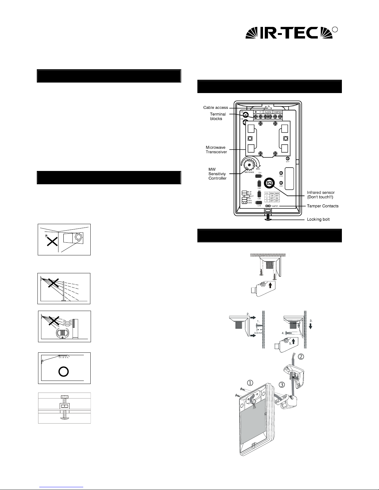
DESCRIPTION
MOUNTING OPTIONS
Ceiling Mount
Wall Mount
Min. 1m
Light
TAM PER
Page 2
MOUNTING & WIRING
With mounting bracket
1. Mount the base of mounting bracket on the
selected position. Lead the cable through the
cable access tunnel of mounting bracket.
2. Open the front cover and carefully remove the
PCB from the bottom case. Lead the cable into
the case and assemble the mounting bracket with
it (as shown on previous page).
3. Connect the cable to the corresponding terminals
according to the following instructions. Replace
the PCB on the bottom case and fix it. Replace
the front cover and then walk test can be
conducted.
Without mounting bracket
1. Open the front cover and carefully remove the
PCB from the bottom case. Select the adequate
knockouts and mount the case on the position.
2. Connect the cable to the corresponding terminals
according to the following instructions. Replace
the PCB on the bottom case and fix it. Replace
the front cover and then walk test can be
conducted.
Wiring Diagram
+
ALARM TAM PER
-
Tamper output (NC)
A
larm output (NC/NO)
Power input (9 ~ 16 VDC
)
TAMPER: Connect to the tamper protection loop.
ALARM: Alarm output (NC/NO)
– : Ground of DC power input.
+: Positive of DC power input.
WALK TEST
It is necessary to carry out a thorough walk test of the
detector to ensure that the correct coverage is being
achieved. Also to ensure that both PIR & microwave
are sensors working to the same detection area.
1. Apply the DC power supply and give about 60
seconds for sensor to warm up. After the warm up
time expires, walk across the detection zones at
normal speed. The red LED will lit when it detects
the motion.
2. If microwave sensor is over sensitive (green LED
remains on), adjust of the thumb wheel of MW
sensitivity trimmer in counterclockwise until ideal
detection range is obtained.
JUMPER SWITCH SETTING
A 6x2-pin jumper switch is available for various
settings of the detector. Please refer the following
instructions for setting options.
Code Description Placed (ON) Removed (OFF)
MW
MW sensor
detection
Enable MW LED
indication
Disable MW LED
indication
ALM
Alarm relay
output
Enable alarm LED
indication
Disable alarm LED
indication
O/P
Output format N.O. output N.C. output
PIR
PIR sensor
detection
Enable PIR LED
indication
Disable PIR LED
indication
Pulse count selection
Code Pulse count 1 Pulse count 2 Pulse count 3
SWA
ON OFF OFF
SWB
OFF ON OFF
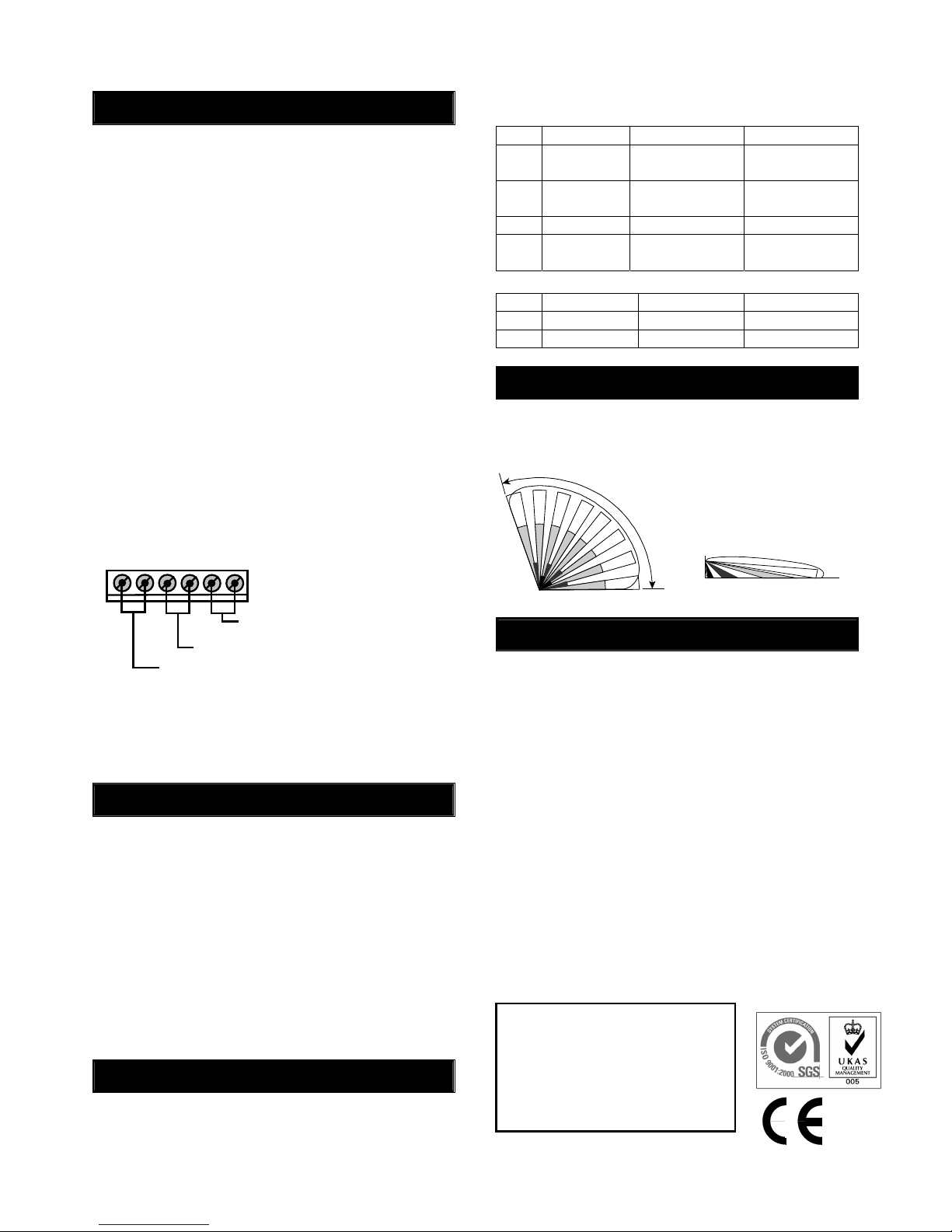
DETECTION PATTERN
Model: DP-550
110°, 15 x 15m at 25°C
Top View Side View
110°
2.2m
1m 2.5m 8m 15m
SPECIFICATIONS
Power supply ............ 9 ~ 16 VDC, 12 VDC typical
Current drain.............30 mA @ 12 VDC
Infrared sensor..........Dual element, pyroelectric
Microwave sensor.....DRO, patch antenna
MW Frequency .........10.525 GHz
MW output power .....6 mW E.I.R.P. peak
Alarm period .............1.5 ~ 2.5 seconds
Alarm output .............NC/NO, 30 VDC, 0.2A max.
Tamper protection ....NC, screw release activated
Mounting height........1.8 ~3.6 m
Mounting bracket......MB-99 included(DP-550-B)
Detectable speed......0.1~3.0 m/sec.
RFI immunity.............Av. 20 V/m (10~1,000 MHz)
Temperature .............-20°C~50°C (-4°F ~ 122°F)
Humidity....................95% RH max.
Dimensions ...............112 x 66 x 45 mm
Warning: Changes or modifications this nit not expressly
approved by the party responsible for compliance could void
the user’s authority to operate the eqipment.
This device complies with Part 15 of the FCC Rules.
Operation is subject to the following two conditions:
(1) This device may not cause harmful interference, and
(2) This device must accept any interference received,
Including interference that may cause undesired
operation.
 Loading...