

Page 1

Industry Canada Compliance Statement
(1) This device may not cause harmful interference, and (2) This device
must accept any interference received, including interference that may cause
undesired operation.
SPECIFICATIONS
433 MHz, FCC Part 15 & IC compliant, license free for the user
Records capacity:
8062 total readings from Field Transmitters
254 switch closures (127 irrigation events, date/time stamped)
254 rain gauge records (up 655 inches)
TROUBLESHOOTING
Please reference the suggestions below, look in the Help section of WaterGraph or
contact Irrometer for further assistance.
No Display: Check battery , replace if <7 .2 Volts. T ry RESET, see below.
Unusual readings: The following are possible readings that may be displayed
instead of a soil moisture, temperature or switch position: DRY -meaning the resistance
is so high that there must be an open wiring connection on a Watemark or a low
temperature reading (frozen) on a temperature sensor , check for broken wires. SHOR Tmeaning the resistance is so low that the circuit must be shorted on a
Watermark, or off scale on a temperature sensor, check for shorts.
No reading reported for too long: Sensor may have lost contact with the soil. Re-install
sensor , being sure to establish good soil contact. Communication ma y be poor from
that location. T ransmission can be checked from the Field T ransmitter to the R eceiver
by pressing the small button in the middle of the transmitter circuit board. Each press
of this button should register another reading on the counter in the display of the
Receiver. Relocate or elevate antenna as necessary for better transmission.
Soft RESET : Use the end of a paper clip or other small object to press the RESET button
located underneath the small hole labeled RESET on the faceplate.
Hard RESET : Disconnect the battery . Press and hold the RESET button down f or at
least 5 seconds. Then re-insert the battery .
Firmware upgrading: Using the “Update Datalogger” command in the “T ools” menu
in WaterGraph, select the new firmware v ersion (.hex format) and press “Open. ” If
the upload process is interrupted, then Monitor will be locked up and it’s display
will stay on “Uploading.” If this happens, use the “Recover Monitor Update”
command in the “Tools” menu to finish the upload process.
WARRANTY: The IRROMETER COMPANY warrants its products against defective
workmanship or materials under normal use for one year from date of purchase.
Defective parts will be replaced at no charge for either labor or parts if returned to
the manufacturer during the warranty period. The seller’s or manufacturer’s only
obligation shall be to replace the defective part and neither seller nor manufacturer
shall be liable for any injury, loss or damage, direct or consequential,arising out of
the use of or inability to use the product. This warranty does not protect against
abuse, shipping damage, neglect, tampering or vandalism, freezing or other damage
whether intentionally or inadvertently.
The Company
Mail: P.O. Box 2424 Riverside, CA 92516
Phone: (951) 689-1701 Fax: (951) 689-3706
TechSupport@Irrometer.com www.Irrometer.com
#89
INSTALLATION AND OPERATION INSTRUCTIONS
The Wireless Monitor Receiver (950R1) automatically records sensor readings received from Field Transmitters (950T1) for collection and display on a
computer. Each Field Transmitter can read up to four (4) Watermark soil
moisture sensors, temperature sensors or Irrometer Model RSU (4-20mA
transducer) sensors. The Receiver unit can also read a direct input from a
switch closure sensor or rain gauge.
SENSOR INSTALLATION
Watermark soil moisture sensors must be “conditioned” prior to installation.
The sensors should be soaked to saturation and then dried fully, twice, and
then soaked to saturation again prior to installation. This “conditioning” of
the sensors ensures quick response to changing soil moisture conditions. If
a sensor is only soaked and then installed, several irrigation cycles must pass
before the sensor will respond accurately. Soak the sensors in a bucket of
water for several hours to saturate them. Hang them up overnight to dry
sufficiently. After “conditioning” they are ready for installation. Sensors
MUST be installed in an active portion of the root zone of the plant to be
monitored, either vertically or up to a 45° angle. Bore a 7/8” (22mm)
diameter access hole to the desired depth, then insert the sensor. Be
careful to ensure a snug fit between the sensor and the surrounding soil.
Then backfill the hole firmly. The access hole can be made by pounding a
7/8” (22mm) diameter bar (or ½” IPS pipe) to the desired depth, then
extracting the bar, being careful not to disturb the soil surrounding the
borehole. With hard or rocky soil, a larger diameter hole can be made with
a soil auger. Mix the auger cuttings with water to create a slurry and pour
into the borehole. Then insert the sensor into the hole. Once the slurry
dries, the sensor will have been “grouted” in to ensure good contact with
the soil. The sensor can be attached to ½” class 315 PVC pipe with a PVC
to ABS cement. The pipe becomes a conduit to protect the sensor wires.
Also, this makes the sensor easier to push into the access hole and remove,
if desired. The top of this pipe section should be capped or plugged so
surface water does not travel down to the sensor. Drill a small hole in the
side of the pipe just above the sensor to allow water to drain away if it
becomes trapped in the pipe.
To measure soil temperature and compensate the accompanying
Watermark sensors on the same Field Transmitter, the temperature sensor
should be installed in the soil near a representative soil moisture sensor.
Only one temperature sensor can be used per Field Transmitter. Bore a
1/2” (13mm) hole in the soil and insert the sensor. Then backfill the hole.
Page 2
If ambient air temperature is to be measured, then no other sensors
should be used on that Field transmitter . Air temper ature measurements
may be somewhat slow to respond due to the potting protecting the
sensor . The measurement range is 20 F to 120F (0-50C), which ma y be
suitable for frost protection monitoring purposes.
Refer to Irrometer installation instructions for proper installation of Model
RSU.
The switch closure sensor is a pressure gauge with a ¼” NPT connection
that has an adjustable switch mounted to its face. The gauge is installed
into the irrigation pipeline. The pressure range of the gauge should be
selected so that the normal system pressure is in the middle third of the
gauge range. The normal system pressure is the set point which will trip
the switch, indicating that an irrigation is taking place.
The Rain Gauge should be installed on a post near the Receiver location.
It wires directly to the terminal strip on the face of the Receiver (950R1).
It should be fully exposed to any rainfall that may occur and be easily
accessible for cleaning and maintenance purposes.
Your own situation ma y be unique because of differences in crop, soils
and climate. Perhaps the most important soil moisture reading is the
difference between today’s reading and that of 3 – 5 days ago. That is to
say , how quickly is the reading going up. A slow increase means the soil
is drying out slowly . But a big jump means the soil is losing water very
rapidly . By analyzing such trends in the readings, you will determine WHEN
to irrigate.
By using sensors at two or more depths in the root system, you will learn
HOW MUCH water to apply. If the shallow sensor shows a rapidly
increasing reading, but the deep sensor shows adequate moisture, you
can run a short irrigation cycle as you only need to replenish the shallow
root profile. If the deep sensor also shows a dry condition, then a longer
irrigation cycle is needed to fully re-wet the entire root zone. The
readings you take after an irrigation or rainfall event will show you
exactly how effective that water application really was.
Your own experience and management will soon point you in the pr oper
direction. You will be practicing “irrigation to need” with the expected
positive results that come from any good management program.
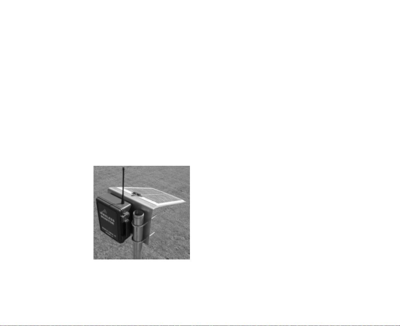
MOUNTING ENCLOSURES
The Wireless Monitor Receiver
should be mounted on a post at
least 4 feet (1.2 m) high and
within 1500 ft (457m) line-ofsight transmission range of the
area where the Field
T ransmi tters are installed. The
solar panel should be oriented
to catch as much sunlight
as possible. The included pipe
clamps can be used for a post
as large as 2 inch (51mm) in
diameter . Alternately , the clamp
holes can be used to attach to a
wooden post with up to 1/4”
(6mm) screws or bolts.
If additional elevation difference exists between the Field Transmitter
locations and the Receiver location, then range may be enhanced. The
radio signal that eminates from the transmitter is oval shaped and can be
disturbed if it hits the ground or canopy. A minimum of 4 ft. (1.2m)
height is recommended, if more exists the range can be lengthened.
2
INSTRUCTION TO THE USER
This equipment has been tested and found to comply with the limits for
a class B digital device, pursuant to part 15 of the FCC Rules. These
limits are designed to provide reasonable protection against harmful interference in a residential installation. This equipment generates, uses
and can radiate radio frequency energy and if not installed and used in
accordance with the instructions, may cause harmful interference to radio communications. However, there is no guarantee that interference
will not occur in a particular installation. If this equipment does cause
harmful interference to radio or television reception, which can be determined by turning the equipment off and on, the user is encouraged to
try to correct the interference by one or more of the following measures:
* Reorient or relocate the receiving antenna.
* Increase the separation between the equipment and receiver.
* Connect the equipment into an outlet on a circuit different
from that to which the receiver is connected.
* Consult the dealer or an experienced radio/TV technician for help.
In order to maintain compliance with FCC regulations, shielded cables
must be used with this equipment. Operation with non-approved equipment or unshielded cables is likely to result in interference to radio and
TV reception. The user is cautioned that changes and modifications made
to the equipment without the approval of manufacturer could void the
user’s authority to operate this equipment.
11
Page 3

If fewer sensors are utilized, the empty ports do not report readings. The
soil temperature sensor is used to compensate the Watermark soil moisture
sensor readings for varying soil temperatures, since temperature affects the
accuracy of the reading. NOTE: Irrometer Model RSU transducers require
auxiliary power.
The Receiver unit can also read
one directly wired sensor input,
Terminal strip
on Receiver
either switch closure or rain gauge.
Either of these inputs can aid in
making irrigation scheduling decisions. The Rain Gauge is used to
record hourly or daily rainfall.
Switch Closure
or Rain Gauge
An Irrometer Switching Pressure Gauge can be used for the Switch Closure
sensor input port, to record whenever the irrigation system is running.
Install the switching gauge on the irrigation pipeline and whenever the
system turns on it registers a switch closure. Be sure to select a Switching
Pressure Gauge with the correct range for the operating pressure of the
irrigation system. The pressure at which the switch closes should be within
the middle third of the gauge operating range. For example, if the irrigation
system’s normal operating pressure is 8 p.s.i., then use a gauge with a
0 to 15 p.s.i.range. The switch closure displays as a horizontal bar, or background bar, indicating the system run time.
You can purchase additional Watermark, Temperature, Switch Closure or
Rain Gauge sensors as necessary to outfit your Monitor for the
characteristics you desire:
200SS-5 Watermark with 5 ft. wire
200SS-10 Watermark with 10 ft. wire
200SS-15 Watermark with 15 ft. wire (stripped & tinned for terminal strip)
200SS-X Watermark w/o wire lead (for splicing to customer supplied wire)
200-TS Soil temperature w/15’ wire
950 RG Tipping Bucket Rain Gauge (.01” or .2 mm increment)
7-*/Switch/DC Switching pressure gauge
(* choose from 15, 30, 60, 10, 200 or 400 psi ranges)
MANAGEMENT
The key element in proper soil moisture measurement is the operator. Taking
the time to interpret your sensor readings will give you a vivid picture of what
is happening with the soil moisture in the root system of your crop. Usually 2 –
3 readings between irrigations is sufficient. The graphical display of your readings show exactly how quickly (or slowly) your soil moisture is being depleted.
Use the following readings as a general guideline:
• 0 – 10 centibars = Saturated soil
• 10 – 30 centibars = Soil is adequately wet
(except coarse sands, which are beginning to lose water)
• 30 – 60 centibars = Usual range for irrigation (most soils)
• 60 – 100 centibars = Usual range for irrigation in heavy clay
• 100 – 200 centibars = Soil is becoming dangerously dry for
maximum production. Proceed with caution!
10
When selecting locations for Field Transmitters, test communication first.
With the Receiver in position, monitor the display screen. With the Field
Transmitter at a potential location, press the test button to send a signal to
the Receiver. If the Counter in the display of the Receiver increases, then
the transmission was successful. Repeat to verify consistency.
The Wireless Monitor Field Transmitters should be located
in the field where sensors readings are desired. Several
different depths can be measured or similar depths can be
measured, which can later be averaged in the software.
Install the sensors nearby at the desired depths. Cut a
piece of 2 inch (51mm) pipe to the desired length to be
used as a mounting post for the transmitter. Note the
finished height of the transmitter antenna should be at
least 4 feet (1.2m). Route the sensor wires through the
pipe and firmly install it in the ground at the sensor
location. Route the sensor wires through the coupling
and short pipe section of the Field Transmitter, then
attach them to the terminal strip on the Field Transmitter
per the drawing in Figure 1. Slide the short pipe section
up over the circuit board and into the cap. Then, slip the
foam wedge over the wires and insert it into the bottom
of the transmitter housing to protect it from moisture and
dirt. If insects are a problem, then the mounting pipe
should be sealed on the inside around the wires with
silicone or spray foam to help protect the radio transmitter.
Insert the coupling over the
mounting pipe and the transmitter
housing to complete the installation.
The coupling can be solvent cemented in place if desired, but the
cap should be left as a friction fit so
the transmitter can be removed if
necessary. Leave sufficient excess
wire to allow for removal of the cap
and transmitter.
SENSOR WIRING
Long runs of sensor wiring are eliminated by using this wireless system. The
sensors wire directly to the Field Transmitter that wirelessly
transmits readings back to the Receiver module. Attach sensor wires to
the appropriate terminals as determined by your sensor selection.
Follow the sensor placement listings below to correspond to the
configuration of the transmitter module you are using. The terminal strips
have spring tensioned lever type terminals. First, insert the wire in the
bottom of the terminal, then push down on the black lever. The black lever
can be lifted with a finger, or small screwdriver inserted in the slot, for wire
removal.
3
Page 4

Each of these positions will correspond to an individual sensor name
assigned when you configure the Receiver module. If soil temperature
compensation is desired, then the 950T1-TW configuration must be used
on each transmitter. If ambient air temperature is being measured, it should
be on a separate transmitter with only a temperature sensor on port 1.
950T1-TW:
Terminal 1: Soil temperature
Terminal 2: Watermark smooth wire
Terminal 3: Watermark smooth wire
Terminal 4: Watermark smooth wire
T erminals GND: T emperature and
Watermark ridged wires
1 2 3 4 GND OUT IN
950T1-W:
Terminal 1: Watermark smooth wire
Ridged Wires
Terminal 2: Watermark smooth wire
Terminal 3: Watermark smooth wire
Terminal 4: Watermark smooth wire
Terminals GND: Watermark ridged wires
950RSU:
Terminal 1: Model RSU black wire
Terminal 2: Model RSU black wire
Terminal 3: Model RSU black wire
Terminal 4: Model RSU black wire
Terminals GND: Auxiliary power ground
Terminal OUT: All RSU red wires
Terminal IN: Auxiliary power positive
Irrometer Model RSU requires auxiliary power (9 to 24 VDC) from an outside
source to power the transducers, such as the 900M-BP solar recharging
battery pack.
Watermark sensors have one smooth wire and one wire with a small ridge
running the length of the wire. Unlike with other Watermark reading
devices, sensor wire polarity must be observed when wiring the sensor to
the 950T1 Field Transmitter. The wires with the ridge always connect to
the ground terminals.
BATTERY INSTALLATION
Field transmitters:
Insert an alkaline 9 volt battery into the holder on the back side of the
circuit board. If battery voltage is low, an alert indicator will appear when
downloaded data is graphed.
Receiver module:
Plug the battery into the Receiver module connector to activate the unit.
A coin cell battery is used to maintain the internal clock in the event of a loss
of external battery power. This coin cel l battery will not operate the radio
receiver or record readings. If 115 VAC power is available at the receiver
location, a plug-in style transformer can be used in place of the battery and
solar panel.
4
16 The date and time is automatically retrieved from your computer’s clock.
17 When you are finished, click on “Send Setup to Datalogger.” This
launches or transfers your configuration to the Monitor’s memory.
18 Your SETUP characteristics can be saved with the “Save Datalogger
Setup” choice from the File menu, for re-programming units.
19 “Retrieve Datalogger Setup” can be used to view the existing
configuration.
WaterGraph software is used for managing the collected data to aid in
making irrigation scheduling decisions. Many functions can be performed:
Retrieving collected data from the Monitor (downloading)
Viewing data in graph form (opening existing files)
Viewing data in spreadsheet form (raw data)
Detailed instructions describing all the features of these various functions
are described in the on-screen documentation available in the pull down
Help menu of the program.
FIELD OPERATION
With the SETUP programmed and the sensors connected, your Wireless
Monitor can now be used to download or display soil moisture tensions.
You may view the most recent reading of the sensors at any time. Simply
push the green button once to “wake up” the display. The display will show
the date/time and base receiver address. A second push shows the date
reading collection began. The next push displays the date/time of the last
reading, the transmitter address and battery status. Push the green button again to display the last four sensor readings on transmitter number
one. Each successive push of the green button will reveal another set of
transmitter readings. After 10 seconds of inactivity, the Monitor display will
go into sleep mode, to preserve battery life. Viewing in-field readings can
aid in making on the spot irrigation scheduling decisions, while the stored
data is used to view the rate of change over time and to evaluate the
performance of irrigations which have taken place.
SENSOR SELECTION
Each Field Transmitter can be programmed to read one soil temperature
and three Watermark sensors or four Watermark sensors or four Irrometer
Model RSU sensors.
9
Page 5

USB drivers will also need to be installed onto your computer:
1 Insert the WaterGraph CD into your computer’s CD drive.
2 Select the USB Driver installation program from the CD
3 Select “Yes” when prompted to install the driver.
4 Follow the on screen prompts, selecting “Next” and accepting the
default choices suggested until reaching the end of the installation.
5 Select “Finish” to conclude the installation.
6 You may now launch WaterGraph by double clicking on the desktop icon.
To assign transmitter and sensor labels for the graph legend (SETUP):
1 Connect the Receiver (950R1) to your Windows® based (PC) computer
(laptop or desktop) with the supplied USB cable. One end connects to
the Receiver at the port labeled “USB Port” and the other end connects
to one of the powered USB ports on your computer.
2 Double click the WaterGraph icon on your desktop to open the program.
3 The first window you will see may say “Choose Language.” If so, select the
language you wish to use. This can later be changed in the File pull down
menu, but the program must be re-started to take effect.
4 The next window you see says “Auto Detect.” This window prompts you to
allow the program to locate the correct COM port on your computer or
allows you to select the appropriate port. Click either “Auto Detect” or
select the COM port from the drop down list and click “Done.”
5 Once the computer has connected with the Receiver, the main program
window will open which says “WaterGraph.”
6 Select “Setup Datalogger.” This will open the Setup window where you
input individual transmitter addresses and sensor names for the graph
legend.
7 First, enter a specific name in the space provided for User/Company Name
(16 alphanumeric characters available using spacebar for blank spaces).
8 Next select which Base Receiver you are programming by choosing from
the pull down menu.
9 Next enter a unique name for the Base Radio Receiver (16 alphanumeric
characters available using the spacebar for blank spaces).
10 Next, enter a unique name for Unit 1 Name (8 alphanumeric characters
available using the spacebar for blank spaces)
11 Then, enter names for each of the 4 sensors that will be connected to
that specific Field Transmitter.
12 Then, following the switch positions listed for Unit 1, adjust the DIP
switch settings on the field Transmitter to correspond exactly. The
diagram below shows the DIP switch positions.
13 Next, the sensor selection will need to be programmed in for the Field
Transmitter as well using the smaller 4 position DIP switch. Follow the
diagram below or the settings listed on the SETUP screen to match the
sensors being installed.
14 Similarly configure every transmitter being used.
15 If you are using a directly wired sensor input to the Receiver, select
either Switch Closure or Rain Gauge from the Switch Mode pull down
menu. If using a Rain Gauge, select the hourly or daily accumulation
interval and inches or mm reporting units.
Programming and addressing Field Transmitters:
Field T ransmitters need to be programmed f or the sensor combinations
attached and individually addressed, as well as addressed to a specific
receiver unit. This programming is done by setting the positions of two
different DIP switches on the circuit board of the transmitter. Diagrams
on the following pages illustrate the location and switch positions as
described in the instructions. On-screen instruction is also provided in
the WaterGraph software program as you go through the setup process
on the computer to configure your system.
Programming the sensor selections:
Programming the sensor selection is done by selecting from among
several preset choices of sensor combinations. The selections are made
by switching the smaller four position DIP Switch to correspond to the
choices as illustrated. A reading interval does not need to be selected.
The unique design of the Wireless Monitor system only records sensor
readings when they have changed, thus eliminating the recording of
unnecessary readings and reducing file size and downloading time. Use
the SETUP function in WaterGraph to create individual sensor names that
will be referenced in the graph legend for easy identification. These
labels will only apply when downloaded to the same computer that was
used to launch the Monitor . The settings ar e stored in a settings file that
can be moved to another computer to retain the sensor labels, if desired.
Addressing the Field Transmitters:
The larger , 7 position, DIP switch is used to address the Field T r ansmitter
and also select the Receiver unit it will communicate with. The first four
positions will address the transmitter. The last three positions will set
the receiver it is to communicate with. Each transmitter must have a
unique address, so the first four positions cannot be the same among all
the transmitters being used per receiver. However , the receiver selection
must be the same among all the transmitters reporting to it. So the first
four positions will always be different, and the last three postions will
always be the same for each system (consisting of one receiver and up
to sixteen transmitters).
Please refer to the following diagrams and the on-screen documentation
when programming with the DIP switches.
8
5
Page 6

Prior to installing the
equipment in the field, the
Field Transmitter units need to
be programmed for the
sensors to be read and
addressed to communicate
with the proper Receiver. This
is done by setting the
positions of DIP switches
located on the circuit board of
the Field Transmitter unit.
Please refer to the diagram for
the proper DIP switch
positions. There are several
sensor combinations to select
from. If you are using fewer
than four (4) sensors, some
of the positions on the
terminal strip will be empty.
Transmitter No. 1
Transmitter No. 2
Transmitter No. 3
Transmitter No. 4
Transmitter No. 5
Transmitter No. 6
Transmitter No. 7
Transmitter No. 8
Transmitter No. 9
Transmitter No. 10
Transmitter No. 11
Transmitter No. 12
Transmitter No. 13
Transmitter No. 14
Transmitter No. 15
Transmitter No. 16
ON
1234567
OFF
ON
1234567
OFF
ON
12345
OFF
ON
12345
OFF
ON
1234 567
OFF
ON
1234567
OFF
ON
1234567
OFF
ON
12345 67
OFF
ON
1234 567
OFF
ON
1234 567
OFF
ON
1234 567
OFF
ON
1234567
OFF
ON
1234567
OFF
ON
1234567
OFF
ON
1234 567
OFF
ON
1234 567
OFF
Receiver No. 1
Receiver No. 2
Receiver No. 3
67
Receiver No. 4
67
Receiver No. 5
Receiver No. 6
Receiver No. 7
Receiver No. 8
ON
1234 567
OFF
ON
1234567
OFF
ON
1234567
OFF
ON
1234567
OFF
ON
1234567
OFF
ON
12345 67
OFF
ON
1234 567
OFF
ON
1234567
OFF
PROGRAMMING
WaterGraph is a Microsoft Windows® based software program with which
you communicate with the Wireless Monitor. With this software, and the
Monitor connected to your computer, either directy or through a telemetry
system, you will program your individual SETUP characteristics and download
collected data to graphically represent the soil moisture characteristics of
your location. These functions are outlined in the following steps:
To install the software onto your computer:
(System Requirements: Win 98/98SE/ME/2000/XP, 5 MB hardrive space, 12MB RAM)
1 Insert the WaterGraph CD into your computer’s CD drive.
2 The installation program will launch automatically. If it does not, using
Windows® Explorer, browse to the CD drive and double click the Setup.exe
file located on the installation CD.
3 Select “Yes” when prompted to install WaterGraph software.
4 Follow the on screen prompts, selecting “Next” and accepting the default
choices suggested until reaching the end of the installation.
6 7
5 Select “Finish” to conclude the installation.
Page 7

file:///C|/Users/Administrator/Desktop/tx1.txt
ASYNC 4800 baud
each bit is 208us +/- 10us
each byte is 10 bits (8 data 1 start and 1 stop) 2.08ms
each byte is sent twice once as true data then once inverted 4.16ms
packet consists of 16 bytes 33.3ms
packets sent 4 times 100ms apart
packet consists of addr,mode,sensor 1,2,3,4 battery and checksum
sync 5ms x 2 x 2 20ms
16 bytes 208s x 10 bits x 2 bytes x 8 bytes per packet 33.3ms
4 packets 33.3 x 4 133ms
100ms off between packets 400ms
total time 533ms
file:///C|/Users/Administrator/Desktop/tx1.txt [10/31/2007 11:02:33 AM]
 Loading...