

Page 1

GHZ MLF/QFN Socket (direct mount - hardwa re)
Page 1 of 2
Assembly Instructions
Tooling holes have to be designed into the target PCB for this version of the GHz MLF/QFN socket
1. Install the socket base assembly on the target PCB with the hardware (0-80 screws and nuts) provided (see Detail A for
orientation).
2. Place MLF/QFN package into the socket. NOTE: MLF/QFN orientation on target PCB is critical.
3. Place the compession plate on top of the MLF/QFN package.
4. Install the socket top assembly on to the socket base asse mbly and swivel to lock into the position.
5. Turn the compression screw clockwise, until it makes contact with the compression plate or the MLF/QFN package.
6. Turn an additional 1/8th of a turn.
Compression Screw
Socket
Top Assembly
Socket Lid
MLF/QFN Package
Socket Base Assembly
Target PCB with SMT pads
Nylon Washer
Hex Nut
Compression plate
Round head Screw
Socket Base
Dowel pin
Angle wire elastomer
Backing Plate
(not necessary for
some sockets)
© 2002 IRONWOOD ELECTRONICS, INC.
Tele: (800) 404-0204
www.ironwoodelectronics.com
Filename: MLI.mcd, Rev A, 9/4/02, WW
Page 2
GHZ MLF/QFN Socket (direct mount - hardwa re)
Assembly Instructions
Page 2 of 2
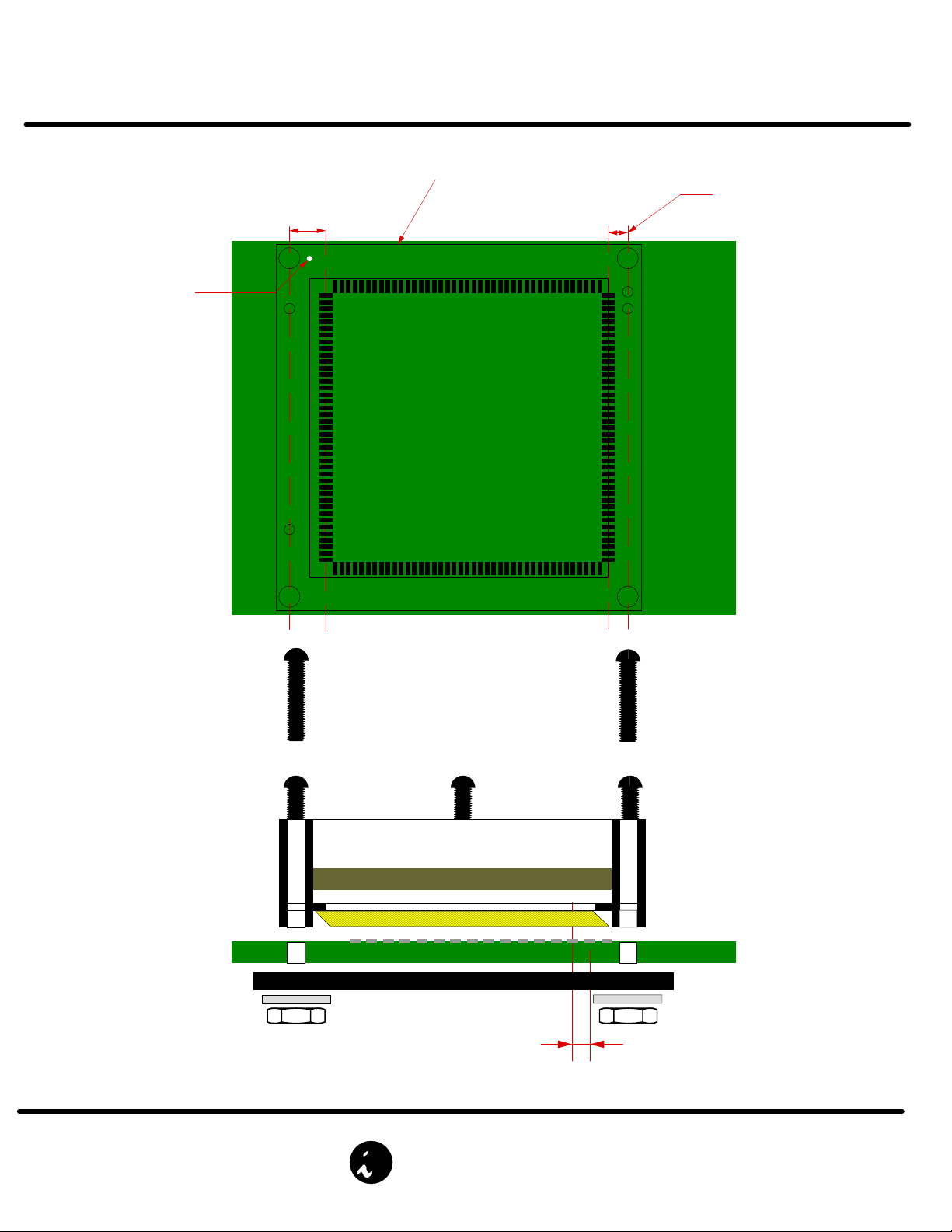
Orientation Mark
Top View
DETAIL A
Socket Base
PATTERN OFFSET
(CLOSER TO RIGHTSIDE
TOOLING HOLES)
Side View
NOTE: WHEN PLACING SOCKET BASE ASSEMBLY,
ORIENTATION MARK SHOULD BE ON THE UPPER
LEFT CORNER AS SHOWN IN THE TOP VIEW.
© 2002 IRONWOOD ELECTRONICS, INC.
Tele: (800) 404-0204
www.ironwoodelectronics.com
Offset
Filename: MLI.mcd, Rev A, 9/4/02, WW
 Loading...