

Page 1
Gull Wing Surface mount Foot Soldering Instructions
The gull wing style, surface mount foot (parts with a 'SF-'
prefix and a '-G' suffix) is designed to solder to a quad
flat pack (QFP) surface mount land pattern. The emulator
foot emulates the physical characteristics of a QFP gull
wing package very closely, allowing the foot to be
soldered to a target board land pattern using the methods
commonly employed in attaching actual QFP packages.
The recommended method is explained below with visual
aids showing the step-by-step process. This method has
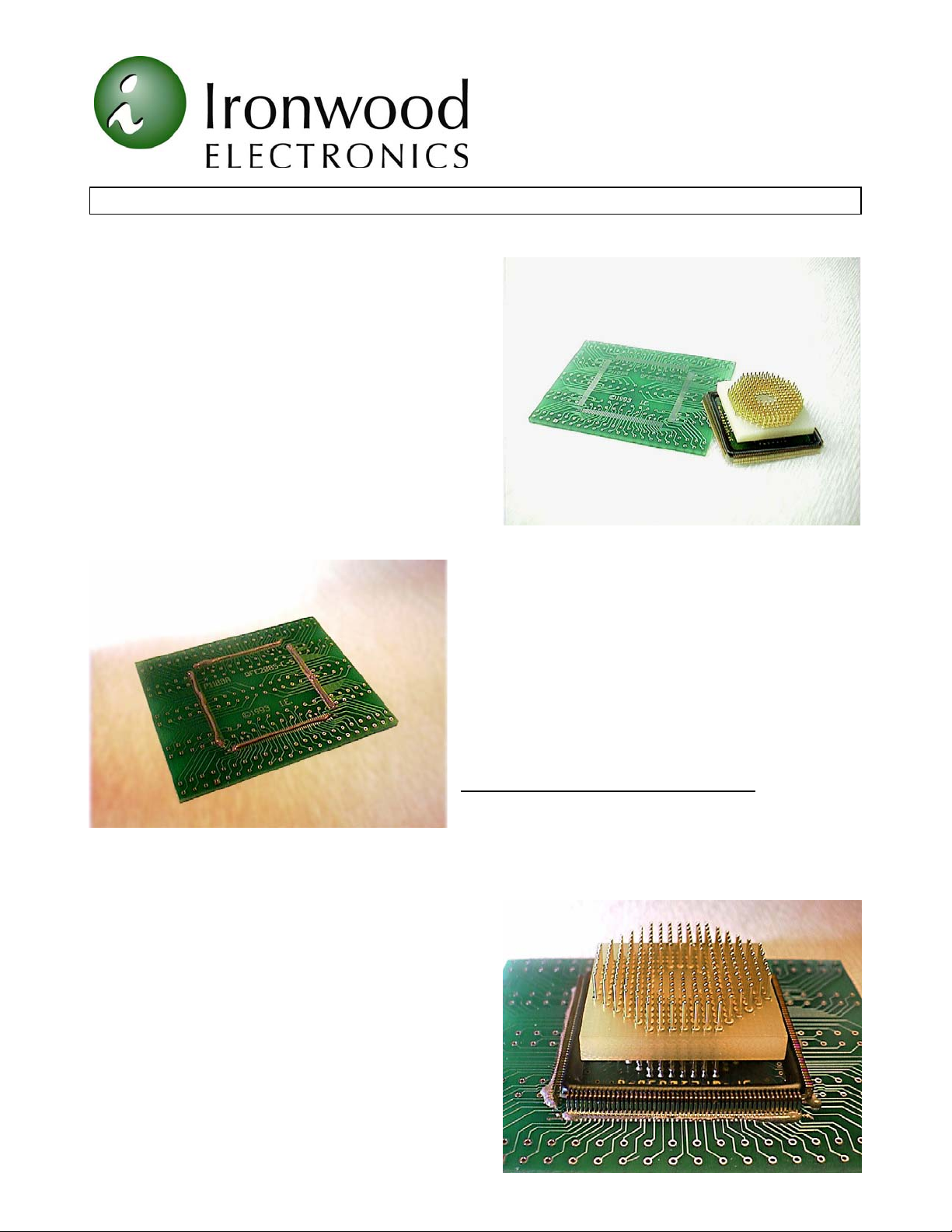
produced very good results. Figure 1 shows the surface
mount emulator foot and a clean target printed circuit
board. The steps involved in the soldering process follow.
CAUTION: During secondary reflow (i.e. mounting the
emulator foot to a board), the temperature profile should
be tightly controlled. The gull wing leads are attached to
Tel: (800) 404-0204
www.ironwoodelectronics.com
Figure 1: Target PCB/Emulator Foot
the emulator foot with 95/5 tin/silver solder(melting point
245°C). If the temperature during reflow exceeds 245°C,
it will cause bridging between the leads or create opens at
the clip head. The peak temperature during reflow should
not reach more than 240°C. Peaks to 260°C are allowed
only if the residence time is less that 40 seconds above
240°C. If you are attaching the emulator board to a target
board using a hot soldering iron, this can easily happen.
We strongly recommend that furnaces are profiled every
day.
REFLOW OVEN - Soldering method #1
(a) Determine an appropriate temperature solder paste for
your application.
Figure 2: Apply Solder Paste
(b) Apply a continuous bead of paste to the target PCB
pads as shown in Figure 2. Cover approximately 1/3 of the
pad between the center of the pad and the outer edge. Begin with this amount and add additional paste after
reflow, if necessary (excessive paste on an initial trial will
be difficult to remove).
(c) Note the target PCB QFP land pattern and the
emulator foot Pin 1 locations.
(d) Align and place the emulator foot onto the solder
paste and land pattern as shown in Figure 3. 'Pick and
place' equipment or a vacuum pen, are recommended (if
they will accommodate the foot), but, handling the foot
by the gold pins and placing on the land pattern by hand
will suffice.
(e) Reflow target PCB with emulator foot in reflow oven
(convection, IR, etc.). The recommended reflow profile is
shown in the Figure 5. Time and temperature settings will
be determined by the manufactures of the solder paste and
Figure 3: Align foot on the lands
Page 2

Tel: (800) 404-0204
www.ironwoodelectronics.com
Gull wing Surface mount Foot Soldering Instructions (continued)
reflow oven. The Ironwood gull wing foot has a larger thermal mass than an actual QFP package, and therefore,
may require longer reflow time and/or higher temperature
settings.
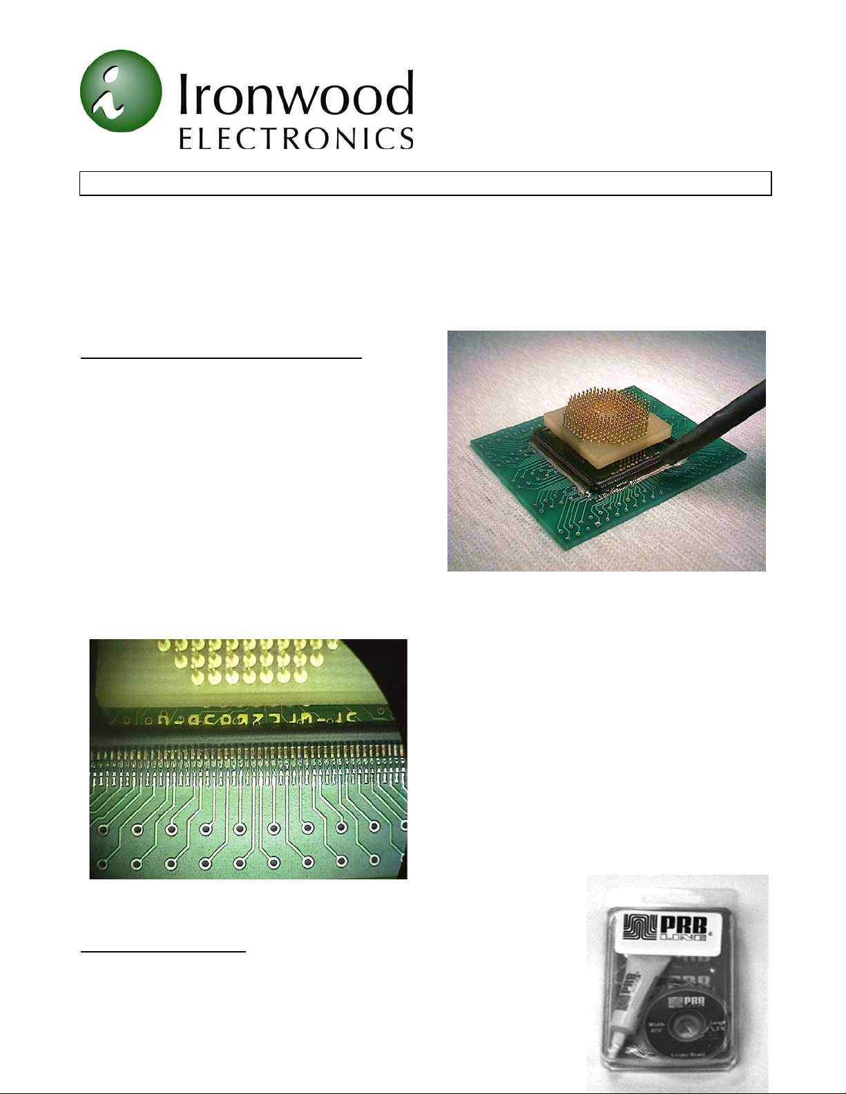
(f) Inspect solder fillets. Add additional solder paste to
solder deficient areas as needed or remove excess with
small tip solder iron and copper desoldering braid (Figure
4). If the solder has not completely reflowed, add solder
flux and repeat step (e).
Because of the construction of the emulator foot, a Low
Temperature solder paste must be used. Set reflow
equipment to the lowest setting that will reflow the solder
paste. Reflow the emulator foot with target assembly in a
temperature range of 185 - 210 degree C. This can be
varied depending upon the profile of the oven and the
Figure 4: Removing excess solder
the foot. It is recommended that reflow oven be set for a minimum time initially. If reflow was not complete,
reflux and reflow for a longer duration.
250
customer assemblies. The above temperature range is safe
for soldering the emulator foot without thermal damage to
Maximum Package Body Temperature
200
Solder Temperature Melting Point
1° to 3°C
150
150 - 180 Seconds
Temperature
(°C)
100
50
<2°C
per Second
Preheat Flux Activation Reflow Cool-Down
0
100 200 300 400 500
Time (seconds)
per Second
<2°C
per Second
Figure 5: Recommended Convection Oven Reflow Profile
HOT AIR TOOL - Soldering method #2
Repeat steps (a) through (d) in method #1. The surface tension present between the solder and the emulator
foot in method #1 will not be present in method #2, due to the fact that only a small portion of the solder in this
method will be liquid at one time. It is necessary therefore, to align the foot over the land pattern with greater
accuracy.
Page 2 of 4 GSI.doc, Rev. C
Page 3
Tel: (800) 404-0204
www.ironwoodelectronics.com
Gull wing Surface mount Foot Soldering Instructions (continued)
(e) Reflow, with a hot air wand/gun, the solder over a few of the pads in opposite corners (diagonally) of the land
pattern (Figure 6).
(f) Check the foot alignment.
(g) Continue by reflowing the remaining solder paste. Add or remove solder as needed (see step (f) in method
1.).
SOLDERING IRON - Soldering method #3
This method has produced very good results but may be
more time consuming than the other two methods.
Caution must be used when touching the soldering iron
tip to the emulator foot. Excessive heat or pressure may
damage the pads on the side of the foot.
(a) Using a small diameter solder wire (approx. 0.015" or
smaller) and a very fine tipped soldering iron, add enough
solder to two opposite corner (diagonal) pads to cover
them.
(b) Align and place the emulator foot over the QFP land
pattern (see steps (c) and (d) in method 1).
(c) Holding the foot in place, by pressing down gently on
the gold terminal pins, place the iron tip on the two pads
to reflow the solder. This will tack and keep the foot in
alignment.
(d) Under a microscope or magnifying lens, if available, solder the remaining edge pads of the foot to the target
Figure 7: Finished Solder Fillets
Removing or Desoldering
Conventional methods can be used to remove a surface mount foot from your
target board, however we recommend the use of PRB Line® D’SOLDER™.;
This SMT device removal product avoids the use of excessive heat that can
compromise the integrity of our product and your target board. The specially
Page 3 of 4 GSI.doc, Rev. C
Figure 6: Reflow using hot air tool
PCB land pattern using a liberal amount of solder (shorts
between adjacent pads can be removed later).
(e) Apply a generous amount of flux along the side of the
foot.
(f) Tilt the PCB and emulator foot at 30 - 45 degree
angle. Start at one corner and pull the tip of the iron
along the side of the foot to remove excess solder
deposits. Clean the tip of the iron often. Repeat this step
several times starting at a point on the foot ahead of the
excess solder. Continue along the side of the foot until
shorts are removed and a fillet is present between feet
and target PCB pads.
(g) Repeat steps (e) and (f) for the remaining three sides.
The finished solder connections are shown in Figure 7.
Page 4

Tel: (800) 404-0204
www.ironwoodelectronics.com
Gull wing Surface mount Foot Soldering Instructions (continued)
formulated alloy and flux make desoldering quick and easy. This solution can be a time and money saver for
many applications. (P/N TL-DS123)
3. filename: GSI.doc, Rev C” with footer autotext filename, Rev. C.Replaced pcb with PCB.
Page 4 of 4 GSI.doc, Rev. C
 Loading...