

Page 1
0.8mm Pitch SMT foot and U G A socket
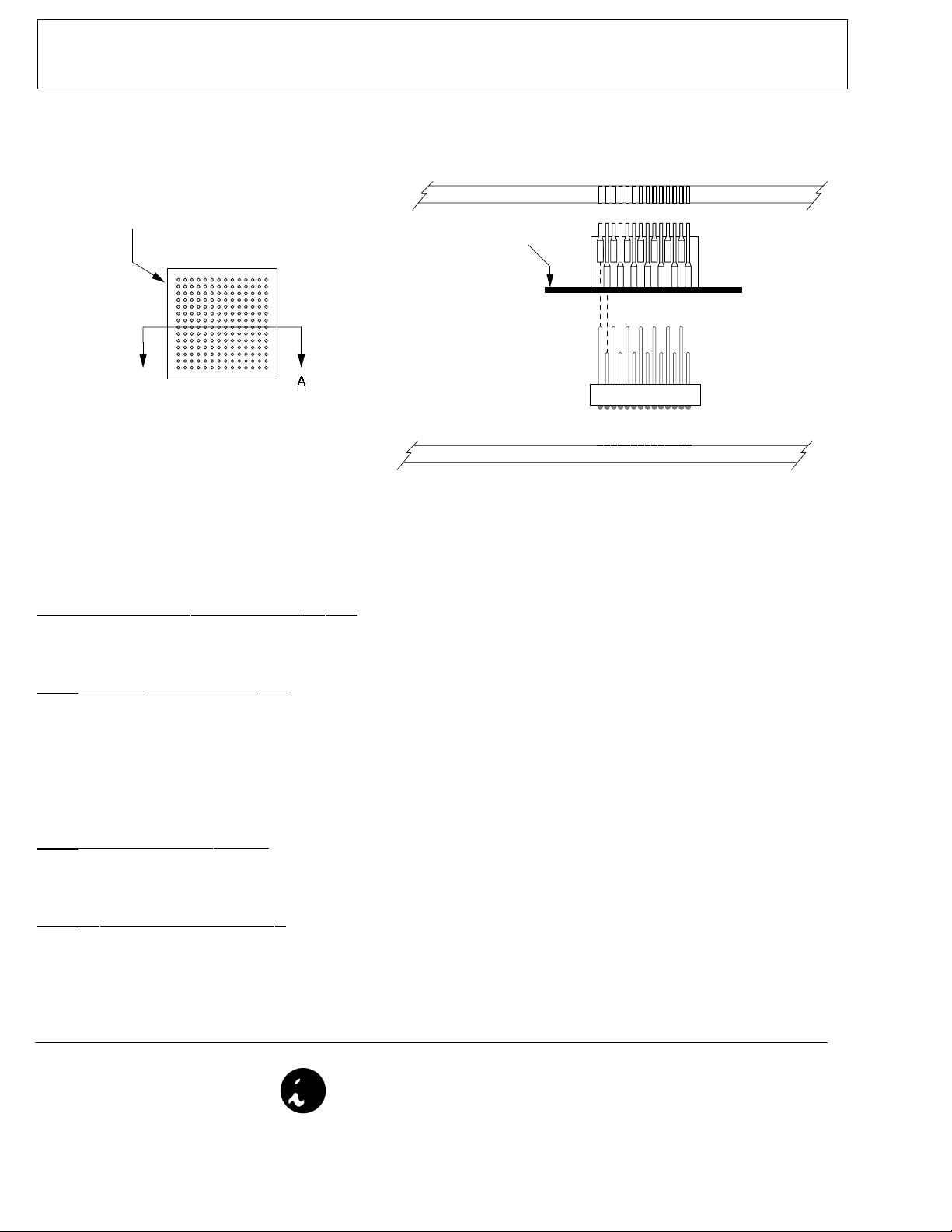
Orientation mark, Align with Target pin A1
A
Top View: Surface mount foot
A ttachm ent and Use
Daughter board
Kapton Tape
UGA socket
Note: Do not remove the kapton tape
from the bottom of the socket until it is
attached to the daughter board.
Surface mount Foot
Target PCB
Cross section: A-A
Step 1 Attach SMT BGA emulator foot to target PCB
A) Attach the surface mount foot such that the orientation mark aligns with pin A1 on the target PCB.
(see the 'BGA Surface Mount Emulator Foot Soldering Instructions' document for details)
tep 2 Attaching socket to Daughter PCB
S
Important: Orient UGA socket with tails (male end) up at all times
A) Remove Kapton tape from ONLY the top of the UGA socket to expose the tails.
B) Align pin A1 of the UGA socket to pin A1 on the daughter boards' through hole pattern.
C) Press the socket into the through hole pattern of the PCB (bottom side of daughter board) firmly and evenly
with a gentle rocking action.
D) Using a soldering ir on, solder the socket to daughter board.
E) Remove the kapton tape from the bottom of the socket.
tep 3 Plugging socket onto SMT foot
S
A) Align the orientation marks of the surface mount foot and UGA socket.
B) Plug the socket onto the SMT foot evenly with a gentle rocking action.
tep 4 Unplugging socket from SMT foot
S
A) Pull the upper assembly off the SMT foot by applying and even force to all corners of the upper assemblys' daughter board. For
large pin count adapters, a slight roc king motion can be used to ease the separation of the two parts. A properly soldered BGA
foot will withstand the forces encountered when inserting and extracting the top assembly.
© 2000 IRONWOOD ELECTRONICS, INC.
Tele: (800) 404-0204
www.ironwoodelectronics.com
Filename: SUI.mcd, Rev C, I Pal, 2/12/01
 Loading...