

Page 1
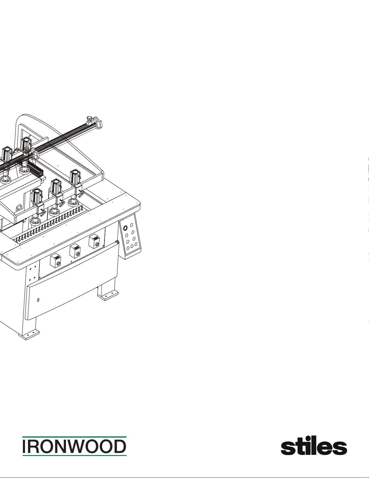
Ironwood DBR50
User Manual
general information.
technical specifi cations. safety considerations.
delivery and installation. inspection.
pre-operation cleaning.
extension fence and stops. drill bits.
connect to power and air.
power connection.
operation and adjustments.
machine operation. maintenance.
assembly.
air supply connection.
features.
Page 2

Table of Contents
1.0 General Information ................................................................ 3
1.1 Thank you
1.2 Before Contacting Stiles
1.3 Features
1.4 Intended Use
1.5 Technical Specications
1.6 Safety Considerations
2.0 Facility Requirements ............................................................... 6
2.1 Floor
2.2 Work Space
2.3 Power
2.4 Compressed Air
3.0 Delivery and Installation ............................................................. 7
3.1 Receiving Your Machine
3.2 Unpack the Machine
3.3 Inspection
3.4 Move Machine to Final Position
3.5 Remove Machine from Pallet
3.6 Level
3.7 Pre-Operation Cleaning
4.0 Assembly ....................................................................... 10
4.1 Extension Fence and Stops
4.2 Drill Bits
5.0 Connect to Power and Air .......................................................... 12
5.1 Power Connection
5.2 Air Supply Connection
6.0 Safety .......................................................................... 13
7.0 Operation and Adjustments ......................................................... 14
7.1 Machine Controls
7.2 Machine Operation
8.0 Maintenance ..................................................................... 18
8.1 Lubrication
8.2 Cleaning
8.3 Inspection
9.0 Troubleshooting .................................................................. 19
9.1 Air Circuit Diagram
9.2 Electrical Diagram
PLEASE REVIEW AND OBSERVE ALL SAFETY
INFORMATION / DIRECTIVES BEFORE INSTALLING,
OPERATING, OR PERFORMING MAINTENANCE ON
THIS MACHINERY.
Ironwood DBR50 | User Manual2
Page 3

1.0 General Information
1.1 Thank You!
Thank you for your purchase of the Ironwood DBR50 double-line
boring machine. At Stiles Machinery, our goal is to ensure that you
are fully satised with your purchase. This manual is provided so that
you may properly assemble, operate, and maintain your DBR50.
Should you need help, our team of dedicated service personnel
are available to answer your questions and provide any resource
recommendations you may need.
Warranty and Support
All Ironwood machines are designed to meet the exacting standards
demanded by craftsmen like you. Ironwood machines include a
one (1) year parts warranty and two (2) years of free 24/7 technical
support beginning at date of shipment. Standard technical support
remains in effect for free for the lifetime of the machine thereafter.
Warranty service work is not covered by manufacturer’s warranty.
Stiles’ service team is available for an additional charge.
1.2 Before Contacting Stiles
Please have your machine model and serial number available when
contacting Stiles Machinery with questions. The machine’s model
and serial number are listed on the metallic plate located on the
machine’s frame.
Information regarding the electrical system and pneumatic supply
are also listed on the metallic plate.
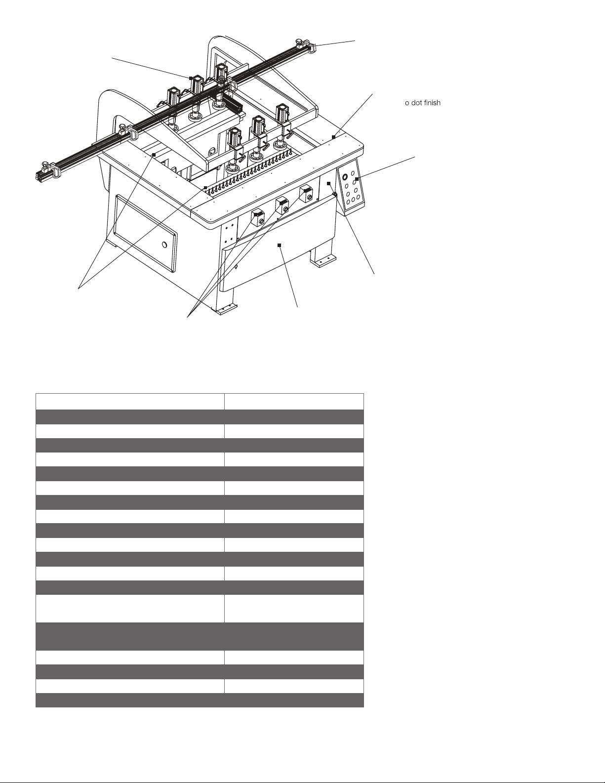
1.3 Features
• 2 independently operated drill blocks have 25 spindles on each
head
• QuickSet rear-fence function allows parallel adjustment of rear
fence to drill block
• 6 Quick-Release pressure-controlled pneumatic clamps rmly
secure workpieces and prevent injury
• Rubber-coated clamping heads prevent workpiece damage
• Convenient pivoting control box
• Adjustable feed and braking speeds for chip-free, through-hole
operation
• Digital readouts for accuracy
• Analog scale (metric and U.S.) allows quick and easy calibration
and are angled for easy viewing
• Second measurement scale is integrated in the rear fence for
precise indexing
• Work table has a large work area
• Compact nish ensures smooth workpiece movement
• Reinforced drill blocks provide additional support for drilling small
workpieces
• Convenient built-in storage for up to 50 additional bits
• Manual-release stops enable quick set ups for 37mm and 44mm
settings
Machine information plate
Stiles Technical Support
616.698.6615
Stiles Parts
800.PARTS.80 (800.727.8780)
Website
www.stilesmachinery.com/ironwood/dbr-series
Machine Model ____________________________________________
Machine Serial Number _____________________________________
1.4 Intended Use
The Ironwood DBR50 is designed for closet, casegood, and cabinet
making. The machine allows easy boring of single or double rows.
You can bore up to 25 holes in each row with just one stroke.
The machine features two independently operated drill blocks for
vertical drilling. Drill bits rise from beneath the workpiece for faster,
cleaner, and safer boring.
The DBR50 allows System 32 line boring, with hole spacing of
32mm to facilitate the easy installation of dowels, brackets, hinges,
cam ttings, shelf support, connecting screws, etc.
Operators can choose auto or manual mode for repetitive drilling.
This robust, ergonomically designed boring machine allows quick
set-up times, digital read-outs for improved accuracy, and a
conveniently large working surface for various applications.
Ironwood DBR50 | User Manual 3
Page 4
Six quick release
Quick-set
pneumatic clamps
Two independently spooled
drill blocks with 25 spindle ends
Digital readouts for
drill block adjustment
rear fence
Large work surface
with micr
Convenient pivoting
control box
0
0
Adjustable feed and
brake speed for better
control of boring speed
Convenient built-in
storage for up to 50
additional bits
1.5 Technical Specifications
Description Ironwood DBR50
Number of Boring Units 2
Pneumatic Clamps 6
Spindles per Boring Head 25
Center Distance Between Spindles 32mm
Work Table Dimensions (d x w) 32¼" x 45¼" / 820mm x 1150mm
Boring Depth 0-2¾" / 0-70mm
Max Workpiece Thickness 4" / 100mm
Quick Chuck 50
Motor Power 3 hp per motor
Working Table Height 33¾" / 845mm
Spindle Speed 3450 rpm
Air Requirement 90-100 PSI
Air Consumption 2 cfm / cycle
Machine Dimensions (d x w x h, w/o fence)
Shipping Dimensions (d x w x h)
55½" x 55" x 50¼" /
1410mm x 1400mm x 1280mm
59" x 57" x 56¾" /
1500mm x 1450mm x 1440mm
Net Weight 1610lb / 730kg
Shipping Weight 1870lb / 850kg
Electrical Connection 230v 3 phase / 460v 3 phase
Amperage 17.4 amps @ 230v / 8.7 amps @ 460v
Ironwood DBR50 | User Manual4
Page 5
1.6 Safety Considerations
Training
For your safety, read these instructions thoroughly before you install
and operate this machine. Always have these instructions available
at the machine for reference.
Observe all codes and regulations that apply to the installation and
operation of this machine.
Keep visitors at a safe distance from the work space.
Keep children away from this and all machines. Childproof your work
area!
Familiarize yourself with the safety notices used in this manual.
CAUTION
If cautions are ignored, personal injury and/or machine damage may
result.
WARNING
If warnings are ignored, serious injury or death may result.
Warning Label
This machine has a warning label attached to ensure safe operation.
It is very important and should be kept clean and never removed.
If the warning label becomes damaged or lost, contact Stiles
Machinery immediately for replacements.
This machine is intended for use by authorized, well-trained
operators only.
Do not operate until you have a complete working knowledge of
the machine and have been properly trained for its safe operation,
correct adjustment, and use. All operators should thoroughly read
and understand this manual and the workings of this machine prior
to operation.
It is essential that all operators be aware of the following:
• The dangers associated with the operation of this machine.
• The use of personal protective equipment for ear and eye
protection.
• The proper positioning of the operator and operator’s hands
relative to the drill bits and pneumatic clamps.
• The principles of machine operation, and proper use and
adjustment of the fence and safety features.
• The correct selection of tooling for each operation.
• The safe handling of the workpiece when boring.
• The safe stacking of the workpiece before and after boring.
Risk of electrical shock
WARNING
Never use the DBR50 for purposes other than its intended use. Do
not modify or remove any guards or other safety features. Improper
use or modications may affect your warranty or result in serious
injury or death.
Ironwood DBR50 | User Manual 5
Page 6
2.0 Facility Preparation
3'-0"
(900 mm)
3'-0"
(900 mm)
3'
3'
*
*
Prior to uncrating your machine conrm that your location can
accommodate the Ironwood DBR50. Follow these guidelines:
2.1 Floor
• The oor must be at and level.
• Although no special foundations are required, a concrete oor is
recommended.
• All oors must have a load-bearing strength suitable for the
machine weight of approximately 1,600 pounds (730 kg).
• If anchoring the machine to the oor, purchase high quality
anchor bolts appropriate to the oor construction and material.
2.2 Work Space
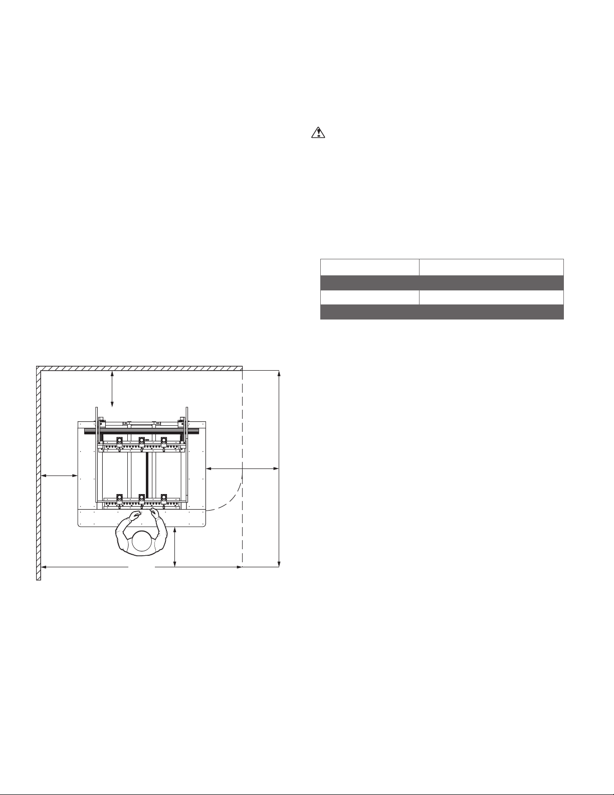
• Provide adequate workspace surrounding the machine.
• Provide proper non-glare, overhead lighting.
• Avoid exposing to any environment where vibration is present.
2.3 Power
WARNING
A licensed electrician must connect the DBR50 to the building
power source.
• Do not use extension cords.
• Be sure that the electrical current of the power source is of
the same characteristics as the 230-volt, or 460-volt, 3-phase
electrical system supplied with your machine. If other machine
voltage capabilities are required, contact Stiles Machinery.
DBR50
Motor 3 hp x 2
Motor Power 230v (3-phase) / 460v (3 phase)
Amperage 17.4 amps @ 230v / 8.7 amps @ 460v
• Ensure the machine is protected with an external over-current
protective device per your local electrical codes.
• Electrical equipment operating conditions:
Air temperatures between +41ºF (+5ºC) and +113ºF (+45ºC).
Relative humidity not to exceed 50% at a maximum temperature
of +113ºF (+45ºC).
Machine clearance requirements*
*Actual clearance requirements on the sides depend upon the length
of the workpiece to the machine.
• Electrical equipment is designed and protected to withstand the
effects of transportation and storage temperatures within a range
of -13ºF (-25ºC) to +131ºF (+55ºC), and for short periods of time
not exceeding 24 hours at up to +158ºF (+70ºC).
• Ensure connection to factory ground system is wired correctly
(IAW local electrical codes and NEC) and not connected to any
electro magnetic interference source such as welders.
2.4 Compressed Air
This machine requires compressed air between 90-100 psi to
operate.
Ironwood DBR50 | User Manual6
Page 7
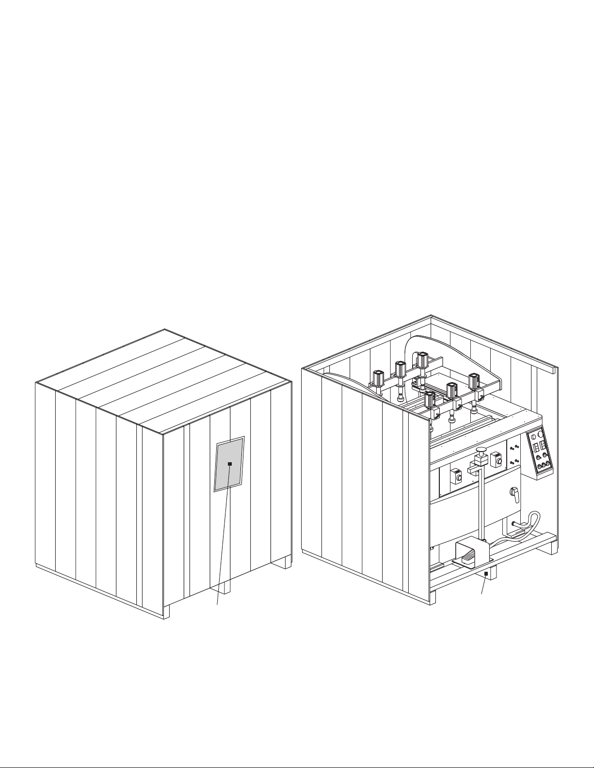
3.0 Delivery and Installation
attached to the outside.
from the pallet while uncrating.
3.1 Receiving Your Machine
You will be contacted to arrange delivery. Your machine will be
delivered by truck to your location. If there is no loading dock, be
sure that you have informed the carrier in advance so that they
deliver using a truck with a lift gate to lower the machine to ground
level.
Before accepting the machine and signing the bill of lading from the
carrier, please inspect crating and machine condition, note potential
damage on the bill of lading, take pictures of potential damage, and
contact Stiles Machinery immediately at 616.698.7500 and ask to
speak with the trafc department.
The machine will arrive fully crated and secured to a pallet. Use a
hand truck or fork lift to move the machine on its pallet as close to
its nal position as possible.
If you do not intend to install the machine immediately after delivery,
store it in a protected, cool, and dry location.
3.2 Unpack the Machine
TOOLS REQUIRED:
• Hammer
• Crowbar
Unpack as follows:
Do not remove the machine from the pallet.
1. Remove and save all paperwork attached to the outside of the
crate.
2. Remove the crating, starting with the top, then remove the four
sides. Use caution to avoid personal injury and prevent damage
to the machine’s nish.
3. Remove the protective plastic from the machine, starting at the
bottom.
The machine arrives fully crated.
Remove and save the paperwork
0
0
0
0
0
0
0
0
0
0
0
0
0
0
0
Do not remove the machine
4. Remove hardware, accessories, and tool kit that may be
shipped inside the machine. If additional accessories are
ordered, they may be delivered separately.
Ironwood DBR50 | User Manual 7
Page 8
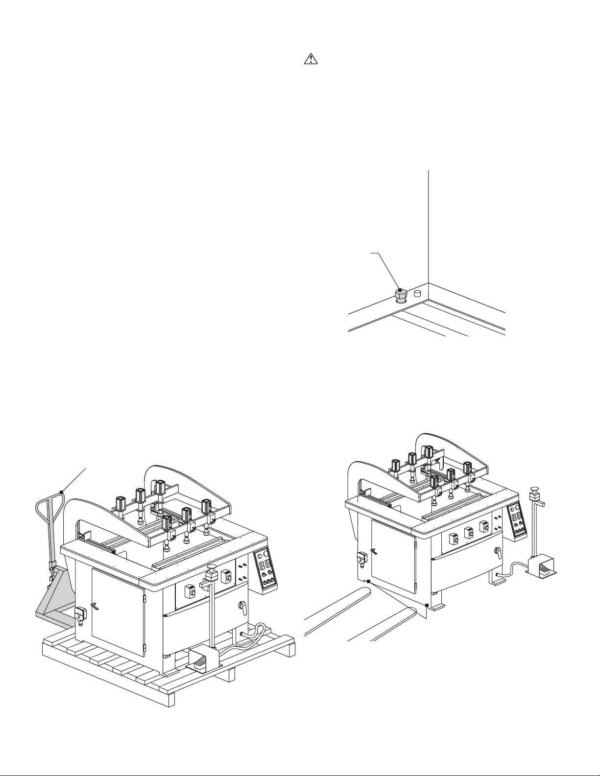
3.3 Inspection
Use a fork lift or hand truck
bolted to the pallet
of any obstacles or wiring.
3.5 Remove Machine from Pallet
Save all containers and packing materials until you are satised
that your machine has arrived in good condition. If you discover the
machine is damaged after you’ve signed for delivery, immediately
call Stiles Customer Service at 616.698.7500.
When you are completely satised with the condition of your
equipment, you should inventory its parts.
Open and check the contents of all containers to ensure all tools,
hardware, and accessories are included. The tool kit should contain
the following items:
1. Allen wrench set (7 pieces)
2. Open-end wrench set (6-pieces: 8x10/10x12/12x14/14x17/
17x19/22x24)
3. Grease gun
4. 3m ruler
5. Cranking handle
6. Paint (3-color set)
7. User manual
3.4 Move Machine to Final Position
Be sure the site is properly prepared. Refer to section 2.0 for details
TOOLS REQUIRED:
• Hand truck or fork lift
Use a hand truck or fork lift to move the machine on its pallet to its
nal location. If using a fork lift, insert the forks as close as possible
to the supports. Make sure fork travel is clear of any obstacles or
wiring.
CAUTION
The DBR50 weighs approximately 1,600 pounds (730kg). For this
procedure, we recommend using a fork lift.
TOOLS REQUIRED:
• Adjustable wrench
When the machine has been placed at its nal location, carefully
remove the machine from the pallet.
The machine is
for transport.
1. From inside the cabinet, remove the bolts that secure the
machine to the pallet at the interior corners.
2. Lift the machine from the pallet by pickup with a forklift.
3. Carefully place the machine into nal position.
to move the machine.
0
0
0
0
0
0
0
0
0
0
0
0
0
0
0
0
0
0
0
0
0
0
0
0
0
0
0
0
0
0
When using a forklift, insert forks
as close as possible to the machine
supports and ensure you are free
NOTE: The boring heads can be damaged if care is not taken when
moving machine.
Ironwood DBR50 | User Manual8
Page 9
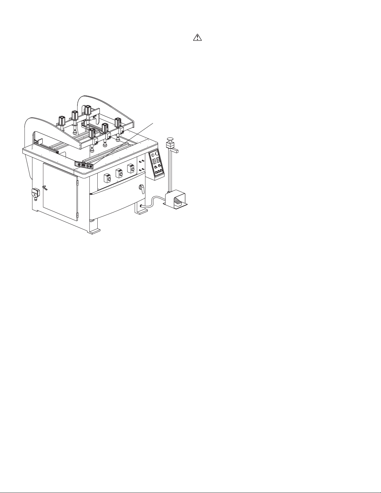
3.6 Level
e to level
3.7 Pre-Operation Cleaning
TOOLS REQUIRED:
• Bubble Level
• Adjustable wrench
Use a bubble level along the length and width of the tabletop surface
to check for level. Use an adjustable wrench to adjust leveling bolts
to level the machine.
Be sur
the machine.
0
0
0
0
0
0
0
0
0
0
0
0
0
0
0
WARNING
Use proper cleaning agents and methods described below. Do not
use gasoline or other petroleum-based solvents. There is a risk of
explosion and burning if these products are used. Serious personal
injury may occur.
Machine Surfaces
After the machine is unpacked, remove the rust preventative oil that
coats the machine. Use a soft cloth and nonammable degreasing
agent, such as Simple Green or other orange/citrus-based cleaner.
Do not use abrasive pads.
Boring Block Quick Chucks
Special care should be taken when cleaning boring block quick
chucks. Completely remove all the grease and dust using a
degreasing agent as mentioned above.
Ironwood DBR50 | User Manual 9
Page 10
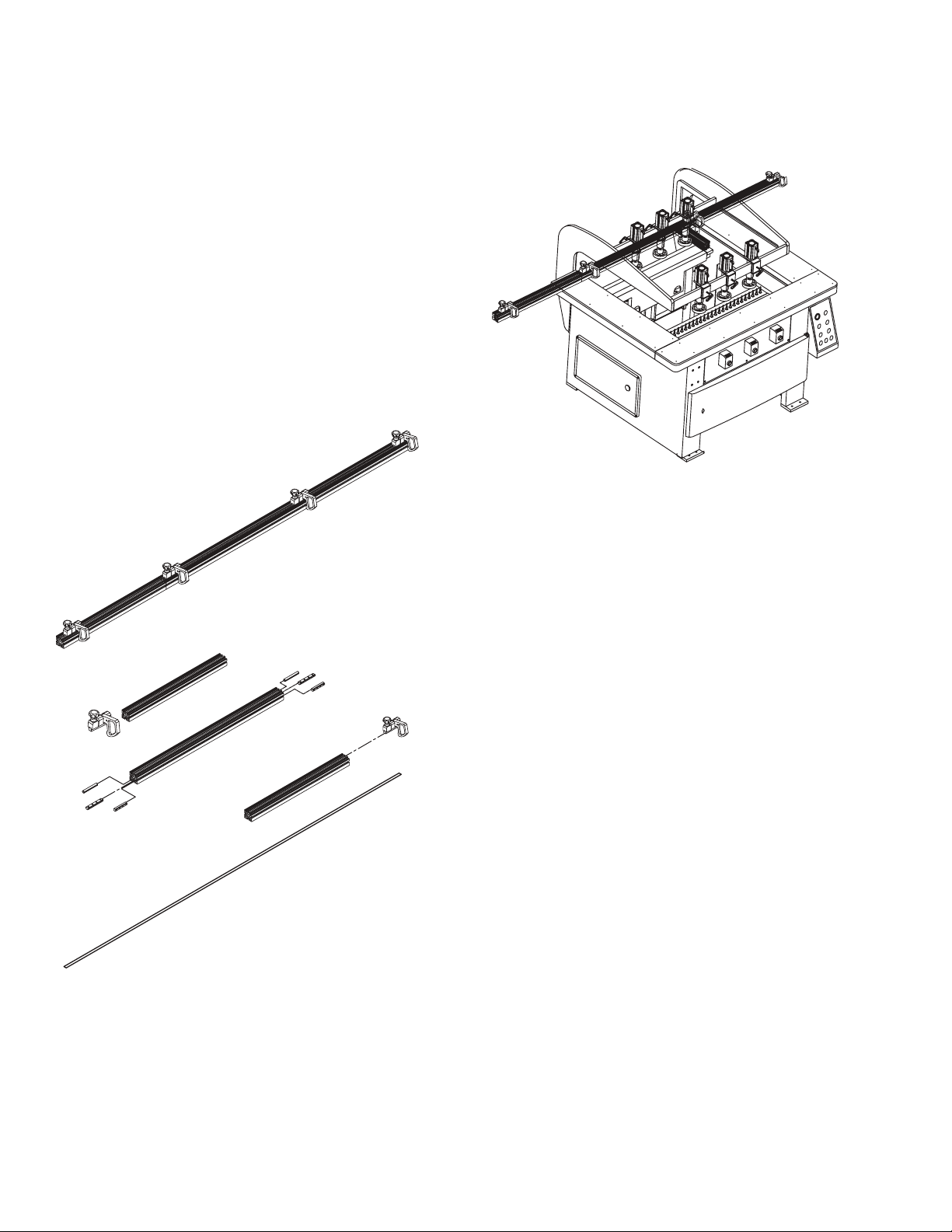
4.0 Assembly
To be assembled:
• Rear extension fence and stops
• Drill bits
4.1 Extension Fence and Stops
PARTS REQUIRED:
• 3 fence sections
• 2 connection rods
• 4 connection bars
• 4 ip stops
• 1 measurement tape
To assemble:
1. Insert a connection rod halfway into the center hole at each end
of the center back fence.
2. Insert a connection bar into the T-slot at each end of the
center back fence; leave approximately half the connection bar
exposed.
3. Tighten two set screws through the center back fence onto
each connection bar.
4. Attach the two side fences to the connection rod at each end of
the center back fence.
5. Tighten the connection bar set screws.
6. Loosen the locking handle on the ip stops.
7. Insert ip stops into the t-slot on the aluminum prole of the
back fence.
8. Slide the ip stops to the desired positions on the fence.
9. Tighten the locking handles.
NOTE: A 3-meter measurement tape is included in the tool kit. The
measurement tape can be mounted on the assembled back fence
to provide accurate ip stop measurements over the entire length of
the back fence.
The rear aluminum fence is assembled using three sections: one
49 ¼" (1250mm) section between two 34 ½" (875mm) fence
extensions attached to the left and right of the center section. The
aluminum fence has one beveled corner. The beveled corner is the
mounting slot for the ruler and should be positioned forward for easy
viewing.
Ironwood DBR50 | User Manual10
Page 11
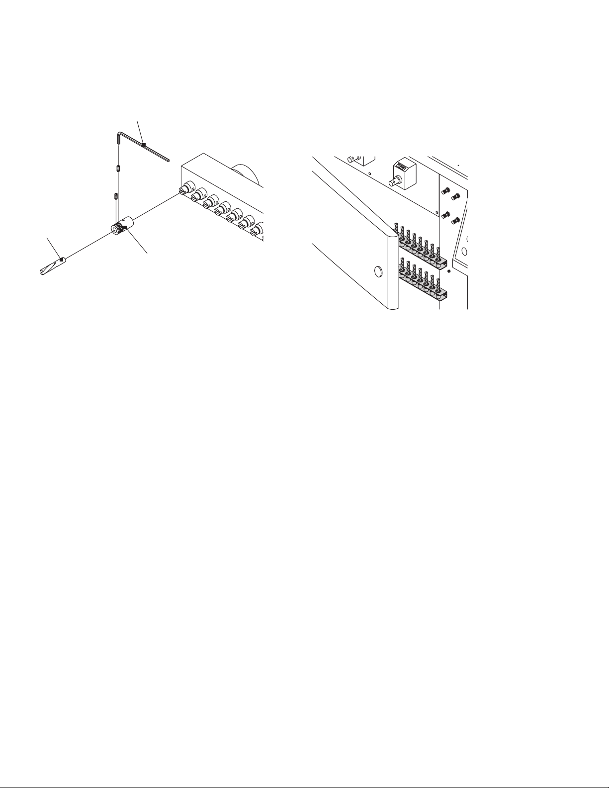
4.2 Drill Bits
Hex Allen wrench
Drill bit
Remove Drill Bits
PARTS REQUIRED: TOOLS REQUIRED:
• Drill bit adapters (supplied) • Hex Allen wrench
• Drill bits (not supplied)
Drill bit quick chuck
1. Determine which drill bit locations will be used to accommodate
the application.
NOTE: Each spindle is colored red or black based on rotation
direction (left or right). Please observe the rotation direction when
selecting tooling for each spindle.
To remove a drill bit quick chuck (with drill bit) from the spindle,
slightly turn the quick chuck to the left and pull up.
Drill Bit Storage Compartment
You can store up to 50 drill bits in the storage compartment behind
the access door at the front of the machine.
204
210
212
211
2. Carefully insert a drill bit quick chuck into the spindle in the
desired positions. Make sure the pin inside the quick chuck is
engaged with the notch on the spindle.
3. Install drill bits into the other quick chucks in the same manner.
4. Tighten the two set screws with an Allen wrench.
5. Make sure the bits are aligned and all at the same height.
Remove and reinstall any out-of-alignment drill bits so that all
are aligned.
Ironwood DBR50 | User Manual 11
Page 12
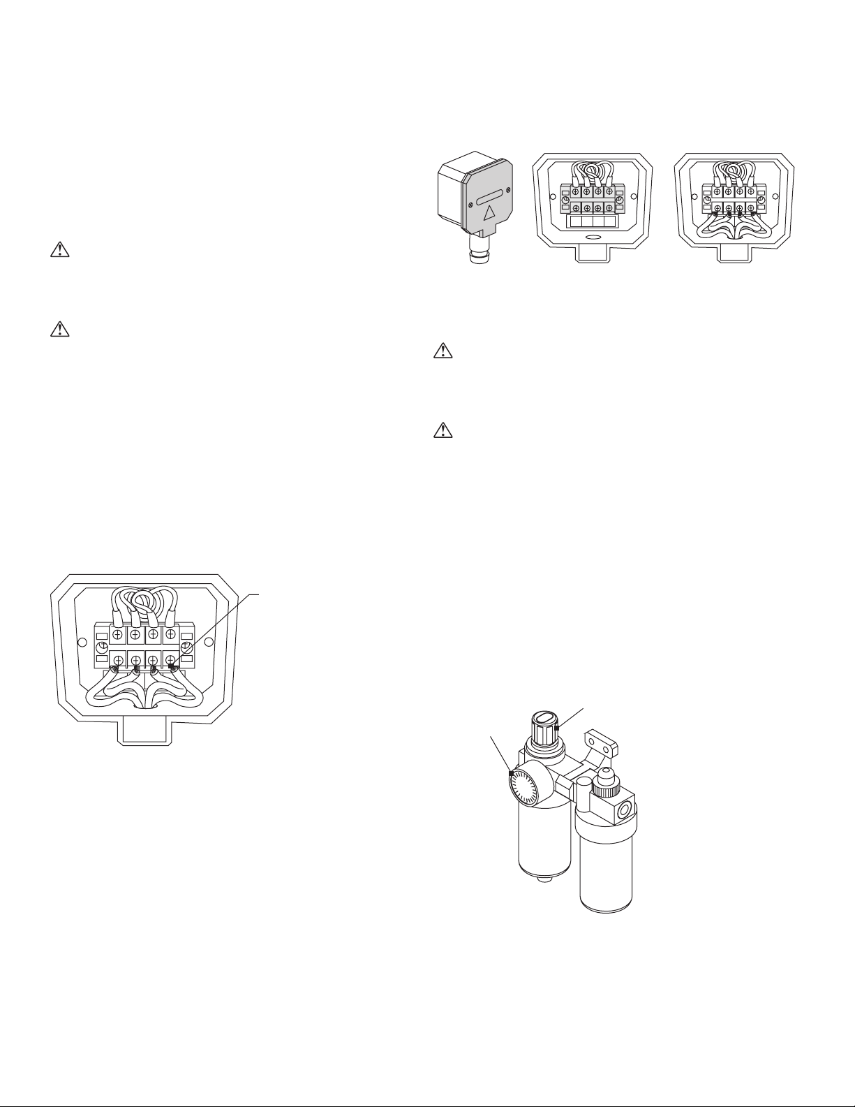
5.0 Connect to Power and Air
the terminal strip box
Remove terminal
terminals
Regulating knob
Pressure gauge
5.1 Power connection
• Voltage – Steady state voltage +/- 10% of nominal voltage.
• Machine needs steady voltage at all times.
WARNING
Before connecting power to the machine, make sure all screws and
fasteners are tightened and all mechanical functions work freely.
WARNING
A licensed electrician must complete all connections to electrical
power.
Before connecting to a power source, conrm that the electrical
current of the power source is the same as the electrical system
supplied with your machine. Ensure the machine is protected with
an external over current protective device per your local regulating
authorities.
Machine must be properly grounded to prevent electric shock.
Never connect the yellow/green wire to a live terminal.
Once connected to power source, terminals are electried even
while the power switch is off.
box covers
WARNING
Always shut off power at source before removing terminal box cover.
Failure to comply with this action may result in electric shock.
WARNING
We have covered some basic electrical requirements for the safe
installation of your machine. These requirements may not cover all
installation requirements. You must conrm that your particular electrical
conguration complies with all local codes. Ensure compliance by
checking with your local municipality and a licensed electrician.
5.2 Air Supply Connection
Remove the clear
plastic insulator
that covers the
L1
1
L2
L3
234
L3
L2L1 PE
PE
L1
1
L2
L3
234
L3
L2L1 PE
PE
Connect power and
grounding wires
To connect power source to the machine:
1. Remove two screws (A) and remove terminal box cover (B).
2. Remove clear plastic insulator that covers the terminals (C).
3. Insert source power cables through opening of terminal box (D).
4. Connect the two power cables to terminals L1 and L2, (E) and
5. Replace the clear plastic insulator (C) and the power box
Proper wiring inside
PE
L2
L1
L3
234
1
L3
L2L1 PE
the yellow/green ground wire to ground terminal (F).
cover (B).
Ironwood DBR50 | User Manual12
Boring carriage adjustment and Quick-Release clamp operation are
pneumatically controlled using the foot pedal.
A ¼" N.P.T. inlet is supplied with the machine’s air tter/regulator to
connect the machine to the air supply.
The air pressure regulator should be set to 90-100 psi.
To adjust the pressure:
1. Pull up on the outer ring of the regulating knob.
2. Turn the regulating knob counterclockwise to let air exhaust to a
pressure level below the desired setting.
3. Turn the knob clockwise to slowly increase the pressure to the
desired setting.
Page 13

6.0 Safety
WARNING
Like all power equipment, there is danger associated with the
Ironwood DBR50. Use caution and follow all safety instructions.
Take every precaution to protect yourself, others around you, and
the machine itself from improper use. Safety is a combination of
common sense, training, and being alert at all times while operating
your machine. If instructions, warnings, and cautions are not
followed, serious personal injury or death may occur.
EYE PROTECTION: Always wear approved safety glasses or a face
shield when operating this machine. Only use eye protection that
meets or exceeds the standards of the American National Standards
Institute (ANSI).
EAR PROTECTION: Always wear ear protection during machine
operation.
DRESS CODE: Do not wear loose clothing, neckties, jewelry, or
gloves that can get caught in moving parts. Conne long hair and
keep sleeves above the elbow.
ELECTRICAL GROUNDING: Your machine must be electrically
grounded. If a cord and plug are used, make certain the machine is
properly grounded. Follow the grounding procedure indicated by the
National Electric Code and local regulating authorities.
GUARDS: Make certain that machine guards are in place and in
good working order. The machine should never be operated without
the safety guards in place.
TOOLING AND ACCESSORIES: Use only recommended tooling
and accessories. Improper tooling and accessories may cause
personal injury or damage to your machine. Regularly maintain
your tools and accessories. Follow instructions for lubricating and
changing tooling and accessories.
POWER: Make sure the starter is in the OFF position before
connecting power to the machine.
Make certain the machine is either unplugged or electrically
disconnected and locked out when performing all maintenance,
cleaning, or machine adjustments. Never leave the machine running
unattended. Always turn the power off and stay by the machine until
the drill spindles completely stop rotating.
HOUSEKEEPING: Before turning the machine on, remove all extra
items on or around the machine. Keep the work area clean and free
of scrap material, sawdust, and other debris to minimize the danger
of slipping. Use compressed air or a brush to remove chips or
debris. NEVER use your hands.
Ironwood DBR50 | User Manual 13
Page 14
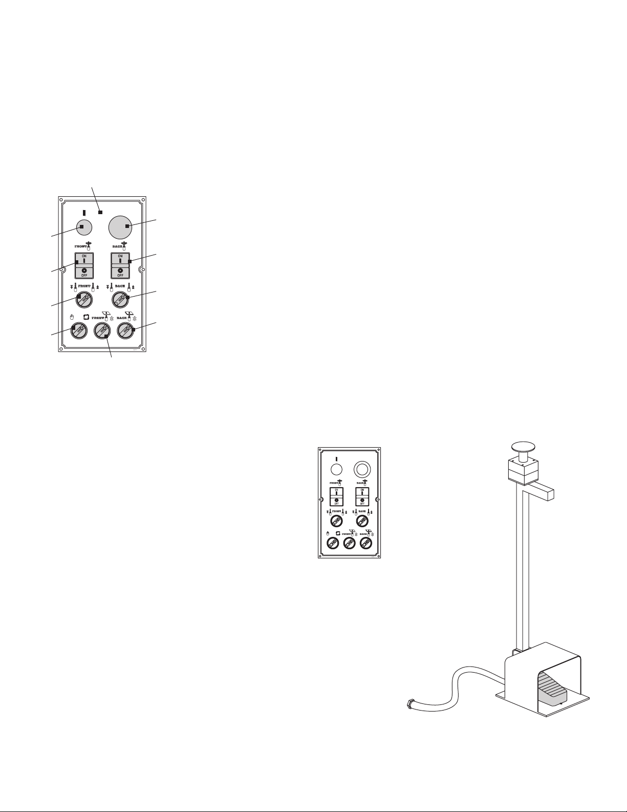
7.0 Operation and Adjustments
The control unit on the front-right
of the machine pivots for
convenient use and controls
the following functions:
2
4
6
9
8
7.1 Machine Controls
1
3
5
7
1. Power On: Press to turn on control power to the machine.
2. Emergency Stop/Power Off: Press in case of emergency to
stop drill rotation or to turn off machine control power.
3. Rear Drill Block On/Off: Press green button to turn drill block
on; press red button to turn off drill block.
4. Front Drill Block On/Off: Press green button to turn drill block
on; press red button to turn off drill block.
5. Rear Drill Block Activation Switch:
a. Manual Mode: Allows manual rise and fall of rear drill block
b. Automatic Mode: Allows automatic rise and fall of rear drill
block
6. Front Drill Block Activation Switch:
a. Manual Mode: Allows manual rise and fall of front drill block
b. Automatic Mode: Allows automatic rise and fall of front drill
block
7. Mode Selector switch
• Position 1 (hand symbol): Manual mode. The boring head
carriage will move pneumatically into the desired position
without spindle rotation. This position can be used to raise
and lower boring head to easily change tooling.
• Position 2 (circular arrows): Automatic mode. The foot
pedal activates the pneumatic movement of both the boring
head carriage and the workpiece hold-down clamp; the
drill spindles will run automatically when the boring head
carriage moves up/forward and stop when it is in a lowered/
back position.
8. Back Through-hole Boring Brake On/Off: Turn the knob to the
right for through-hole applications; turn to the left to turn off.
The switch causes the drill bank to slow down before punching
through top of panel to prevent chipout.
9. Front Through-hole Boring Brake On/Off: Turn the knob to the
right for through-hole applications; turn to the left to turn off.
The switch causes drill bank to slow down before punching
through top of panel to prevent chipout.
Foot Pedal
The foot pedal activates the pneumatic movement of both the
workpiece hold-down clamps and the boring head carriages.
Ironwood DBR50 | User Manual14
Page 15
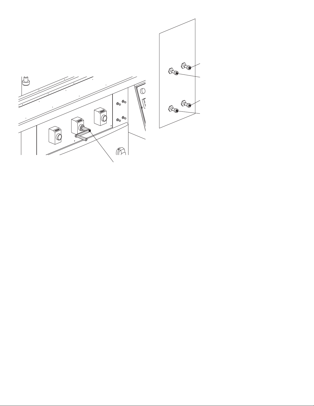
Boring Depth and Back Carriage Position
e depth and
back carriage position
Back boring head brake speed
Front boring head brake speed
The control panel on the front of the machine body lets you precisely
adjust the boring depth and rear boring head carriage position.
• Left knob: Controls boring depth of rear carriage.
• Center knob: Controls position of rear carriage.
• Right knob: Controls boring depth of front carriage
0
0
0
0
0
0
0
0
0
0
0
0
0
0
0
Front boring head rise rate
Back boring head rise rate
Speed Control
Use crank handle to
adjust bor
A crank handle is provided to operate these controls. Digital readout is
provided at each control for accurate setup of each function.
1. Back Boring Head Rise Rate: Turn the knob counterclockwise
to increase the speed at which the back drill block travels up
during the boring cycle. Turn knob clockwise to decrease rise
speed.
2. Front Boring Head Rise Rate: Turn the knob counterclockwise
to increase the speed at which the front drill block travels up
during the boring cycle. Turn the knob clockwise to decrease
speed.
3. Back Boring Head Brake Speed: Controls the rate at which the
back boring head brakes for through-hole drilling applications.
Turn the knob counterclockwise to increase speed. Turn the
knob clockwise to decrease speed.
4. Front Boring Head Brake Speed: Controls the rate at which the
front boring head brakes for through-hole drilling applications.
Turn the knob counterclockwise to increase speed. Turn the
knob clockwise to decrease speed.
Ironwood DBR50 | User Manual 15
Page 16
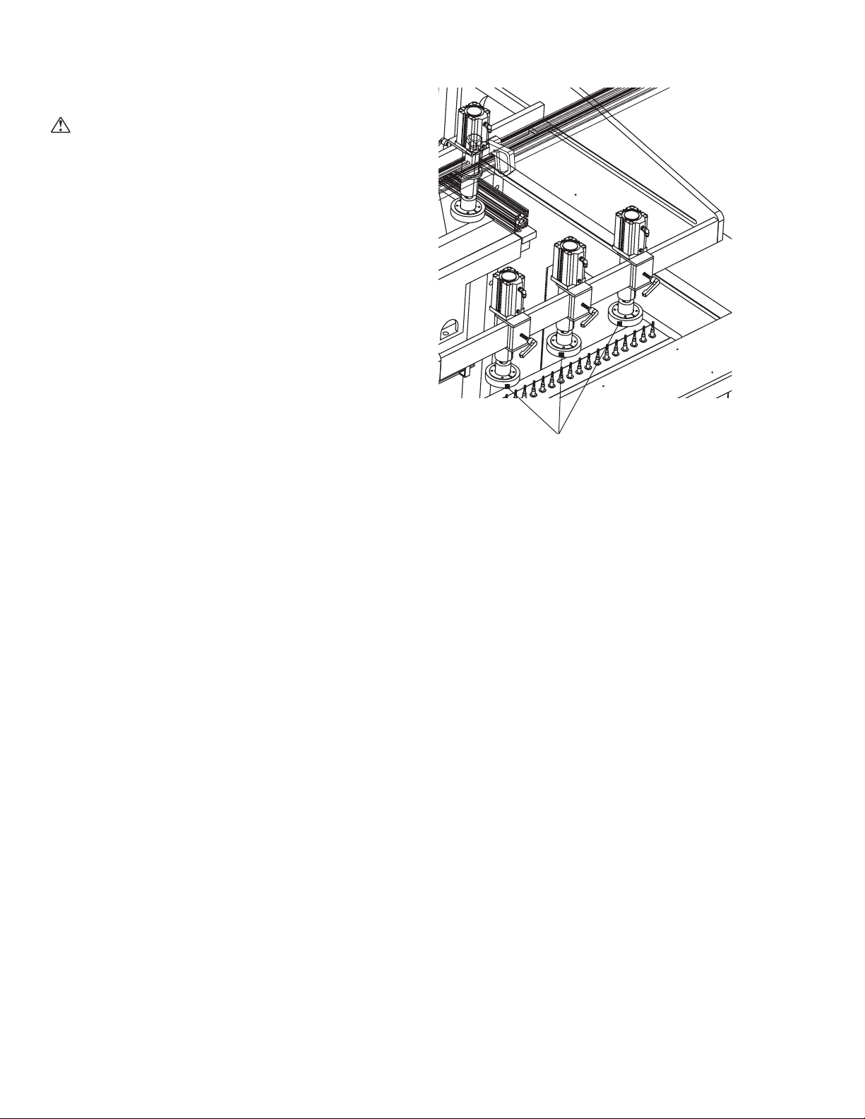
7.2 Machine Operation
Step 1: Activate air supply to machine
WARNING
When air pressure is rst applied to the machine, the boring head
carriage may move. Do not stand behind the machine.
NOTE: The air supply must be on to make certain adjustments and
enable movement of the workpiece hold-down clamps and boring
carriage.
Step 2: Turn on power to machine
Step 3: Ensure air pressure is correct
Step 4: Select operation mode
There are two operation modes available on the DBR50 machine.
Manual Mode (hand symbol): Use for manual setup of the machine.
Turn the knob to the left for manual control. The boring head
carriage will move pneumatically into the desired position without
spindle rotation, unless spindle rotation is manually turned on.
Automatic Mode (circular arrows): Use for normal machine
operation.
Turn the knob to the right for automatic up/down movement
of the boring head carriages. The foot pedal activates the
pneumatic movement of both the boring head carriages and the
work hold-down clamp. The drill spindles will run automatically
when the boring head carriages move up and stop when they are
in a lowered position.
Step 5: Set boring depth
Attach the crank handle to the left or right digital readout to set
the boring depth for the back and front carriages. The depths are
displayed in millimeters (mm) on the integral digital readouts for both
controls.
To adjust:
1. Turn the crank handle to change position of boring depth,
observing position on digital readout.
Step 6: Position rear boring head
The rear boring head can be adjusted to change the spacing
between the front and rear boring heads by using the center digital
readout.
To adjust:
1. Turn the crank handle to change position of the rear boring
head, observing position on the digital readout.
Step 7: Position the workpiece hold-down clamps
Hold-down clamps
Position the hold-down clamps according to the dimensions of your
workpiece to securely hold it in place while boring.
To accommodate workpiece thickness:
1. Place the workpiece on the table under the hold-down clamps.
2. Lower the hold-down clamps to within an inch of the surface of
the workpiece.
3. Lock the hold-down clamps in place.
To accommodate workpiece width:
1. Loosen the lock lever for each hold-down to be adjusted.
2. Move the hold-down(s) right or left to the optimal position to
secure your workpiece.
3. Tighten the lock levers.
NOTE: A minimum of two workpiece hold-down clamps should
always be used when possible.
To reposition the hold-down assembly:
1. Loosen the lock levers at each end of the assembly.
2. Move the assembly forward or back as needed.
3. Tighten the lock levers.
Ironwood DBR50 | User Manual16
Page 17
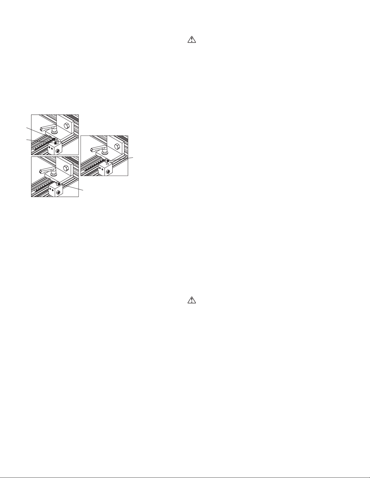
Step 8: Position ip stops
A: 37mm stop position
B: 44mm stop position
A
B
Position the four ip stops on the fence according to the dimensions
of your workpiece and the desired boring points. The stops can
be moved to any point along the fence. The fence has an integral
measuring guide with magnifying lens for precision set-up.
1. Loosen the ip stop locking levers.
2. Slide the ip stops to the desired positions on the fence.
3. Tighten the locking levers.
Step 9: Position QuickSet rear fence
A
B
Position the rear fence in proper relation to the drill block for your
application.
1. Loosen the locking handles on the rear fence.
2. Move the fence forward or back as needed.
3. Tighten the locking handles.
Two stop-block positions enable quick and easy 37mm or 44mm
setting:
1. Depress the button on the manual release stop and move to
the desired setting.
2. Release the button.
3. Repeat for the other stop.
Step 11: Boring the workpiece
WARNING
Do not attempt to operate machine if you are not completely familiar
with its operation. Obtain immediate advice from a supervisor,
instructor, or other qualied personnel.
Use of this machine requires that you give your work your undivided
attention, and careless acts or not paying close attention to work
being performed may result in serious injury to yourself and/or
others. Never operate this or any machine under the inuence of
drugs, alcohol, or any medication that may impair judgment.
Do not bore warped wood. The workpiece must sit at on the table
without rocking.
Dust created by manufacturing activities may be harmful to your
health. Your risks from exposure may vary. Always work in a wellventilated area and wear safety approved, protective dust masks
specically designed to lter out microscopic particles.
Once fences, depths, and rear boring head are properly set for
operation:
1. Turn on air supply and power supply to machine.
2. Press control power on button.
3. Place the workpiece in the desired reference position against
the fences and/or ip stops.
4. Bore your workpiece:
a. If in manual mode, you should not bore the workpiece.
Switch to automatic mode.
b. If in automatic mode, press the foot pedal; the drill spindles
will run automatically when the boring head carriage moves
up/forward and stop when it returns to the lowered/back
position.
5. Remove the workpiece.
WARNING
Never remove the bored piece until the boring cycle is complete.
Step 10: Set feed rates
Feed rates are determined by the type of wood and drilling
operation. In general, hard woods require a lower feed rate; soft
woods require a faster rate. Through-holes require a slower rise rate.
To reduce the feed or brake rates for the boring head carriage, turn
the rise rate and brake rate adjustment knobs clockwise for the front
and rear boring head. Turn counterclockwise to increase the feed or
brake rates.
NOTE: If there is burning on a drill hole or chipout on a through-hole,
feed rate is too fast or too slow. Adjust as needed based on the
material being machined.
Ironwood DBR50 | User Manual 17
Page 18
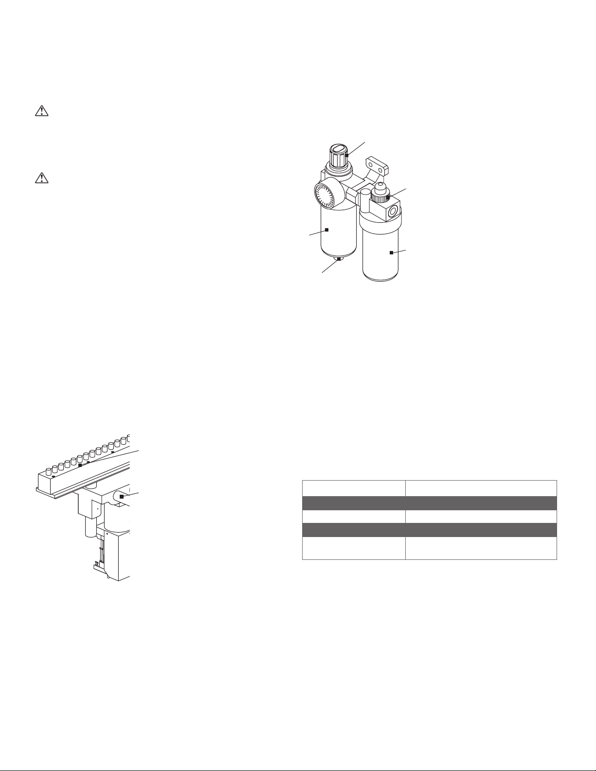
8.0 Maintenance
Lubrication point
A
E
B
C
WARNING
Before performing any type of maintenance or adjustments, make
certain that the machine is disconnected from its power and air
source and completely shut off.
WARNING
Never operate the machine until it has been properly lubricated and
all necessary maintenance work has been completed.
NOTE: After changing a setting, making an adjustment, performing
repair/maintenance work, or troubleshooting, please check that all
applicable safety functions are working properly before performing
another operation.
Clean all machine parts and surrounding areas daily.
Keep a maintenance record and perform recommended
maintenance checks.
8.1 Lubrication
Weekly, clean and lightly oil the drill head guide bars and the
positioning screw of the rear boring head carriage using an ISO
VG32 oil.
Every 1,000 hours of machine operation, lubricate the boring head
using a grease gun and a non-melting moly grease. Apply no more
than 6 grease-gun strokes.
Pneumatic System
D
Periodically ll the oil reservoir (B) with pneumatic oil. Use highquality pneumatic oil such as VG32 or other approved lubricant.
Drain and rell oil if there is condensation inside the reservoir (C). To
drain, press the knob (D).
NOTE: Reduced air ow can cause lack of lubrication. Be sure air
ow is properly adjusted to avoid mechanical damage from lack of
lubrication.
8.2 Cleaning
Blow dust from the machine frequently to avoid buildup of waste
material, dust and other debris.
for boring head
Guide bars
Spindle bearings are permanently lubricated and require no further
lubrication.
Spindle bearings may purge grease during the rst 20 hours
of operation. Wipe away any excess grease before starting the
machine.
8.3 Inspection
Feature Interval/Situation
Boring head and bits Every use
Emergency stop Everyday – by functional test
Pneumatic system Every day
Electrical cabinet/system Monthly: wiring terminals loose, insulation
deterioration, vacuum dust
Ironwood DBR50 | User Manual18
Page 19
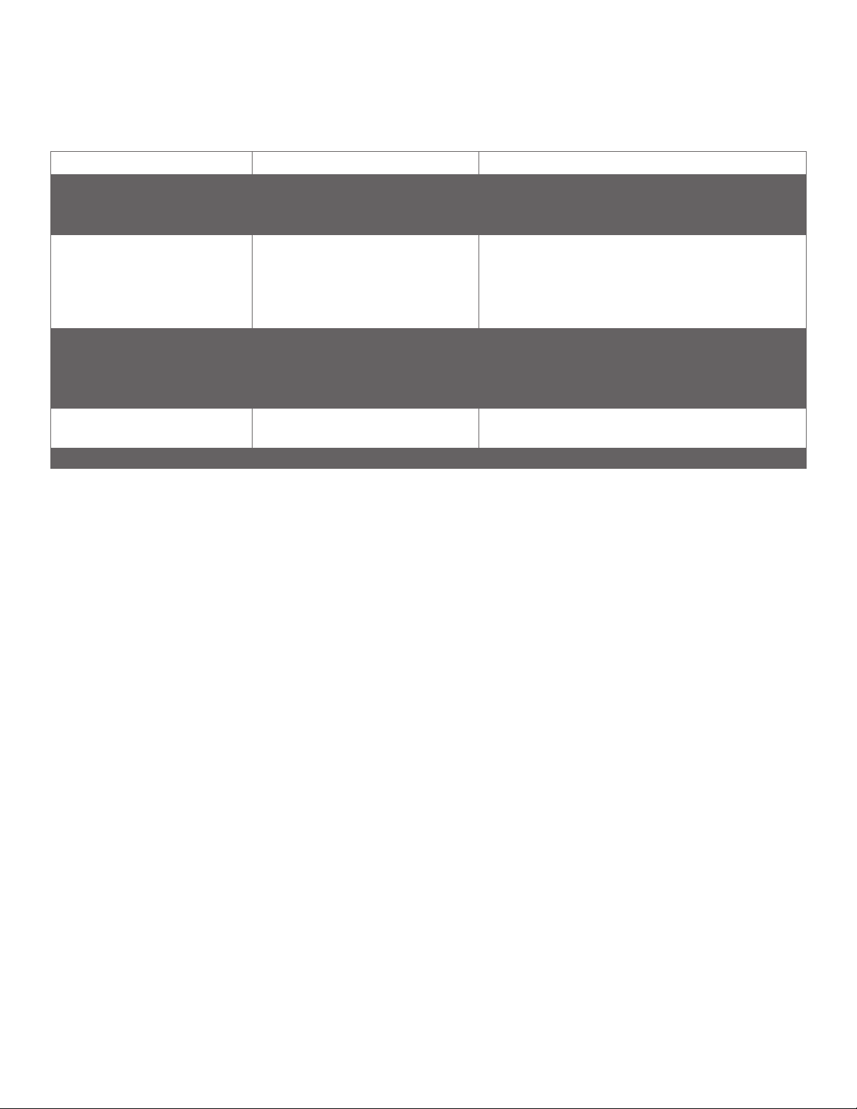
9.0 Troubleshooting
Trouble Possible Cause Solution
Motor won’t start Overload is tripped
Improper voltage
Failed motor
Drills are burning wood Drill feed speed too fast
Drill feed speed too low
Dull tooling
Improper tooling
Drills are chipping material on through
hole boring
Motor not starting when foot pedal is
pressed
Drill block making abnormal noise Bad bearings or broken gears Call Stiles Technical Support
If you cannot resolve your issue, contact Stiles Technical Support at 616.698.6615.
Brake not switched on
Brake speed too fast
Brake worn
Brake not adjusted in correct position
Machine in manual mode
Bad electrical switch
Reset overload
Check voltage to motor
Rotate motor by hand and Ohm out motor
Slow down feed speed
Speed up feed speed
Sharpen or replace tooling
Ensure correct tooling for application (including rotation direction
of tools and spindle)
Turn brake switch on
Slow down speed of brake
Replace brake
Adjust brake to proper adjustment point
Switch to automatic mode
Call Stiles Technical Support
Ironwood DBR50 | User Manual 19
Page 20
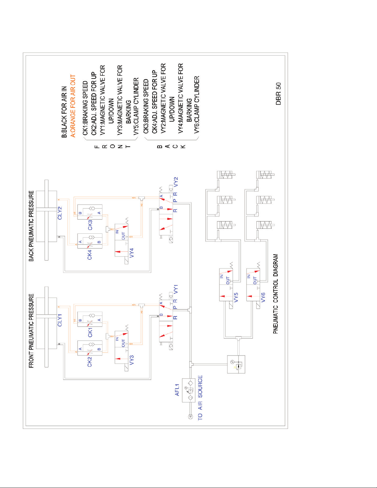
9.1 Air Circuit Diagram
Ironwood DBR50 | User Manual20
Page 21
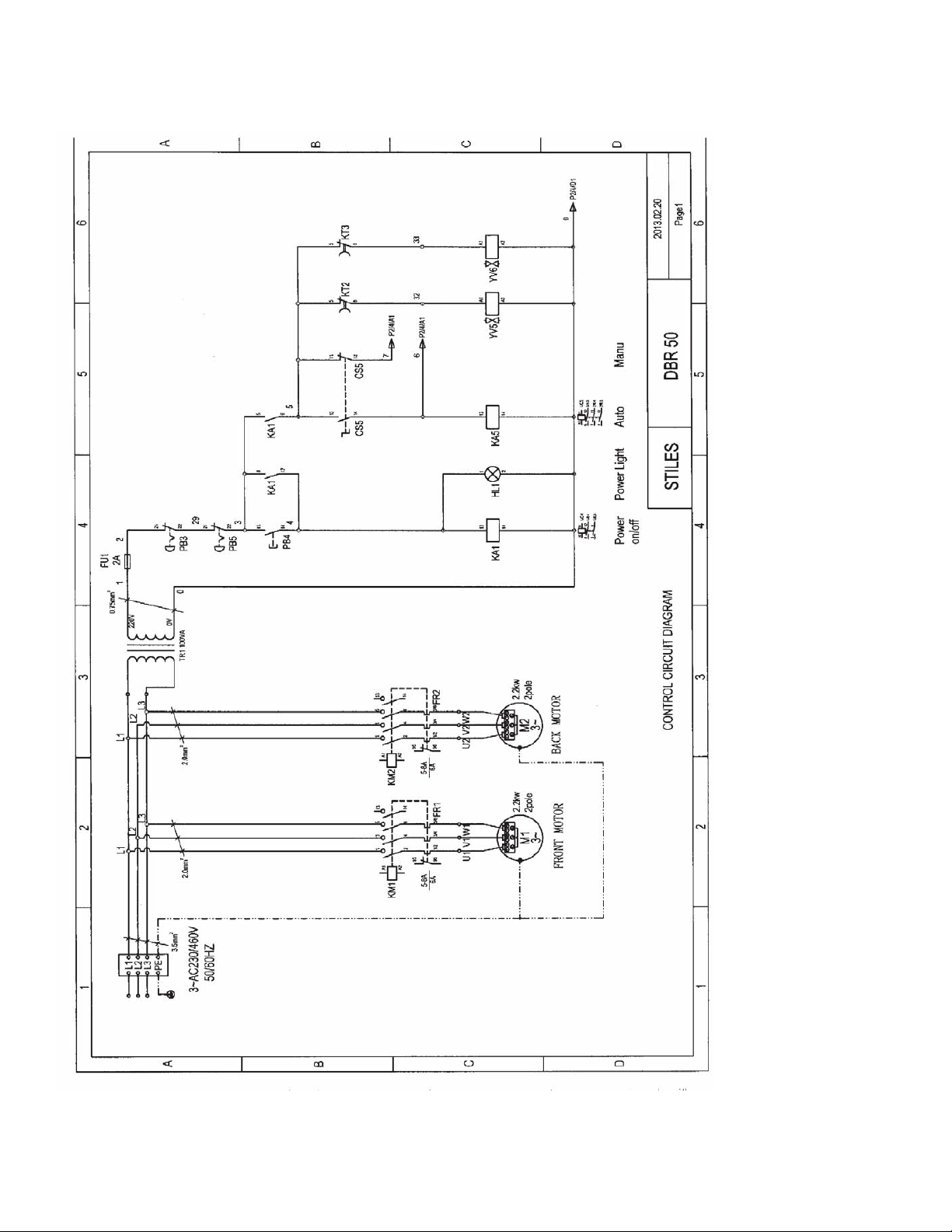
9.2 Electrical Diagram
Ironwood DBR50 | User Manual 21
Page 22
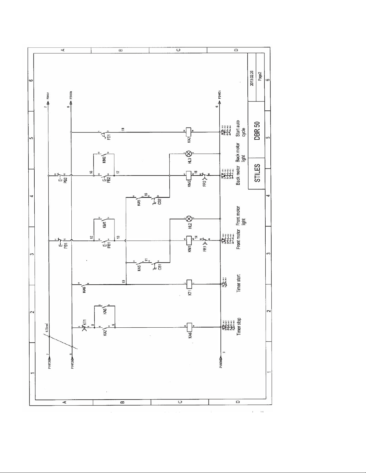
9.2 Electrical Diagram (Continued)
Ironwood DBR50 | User Manual22
Page 23
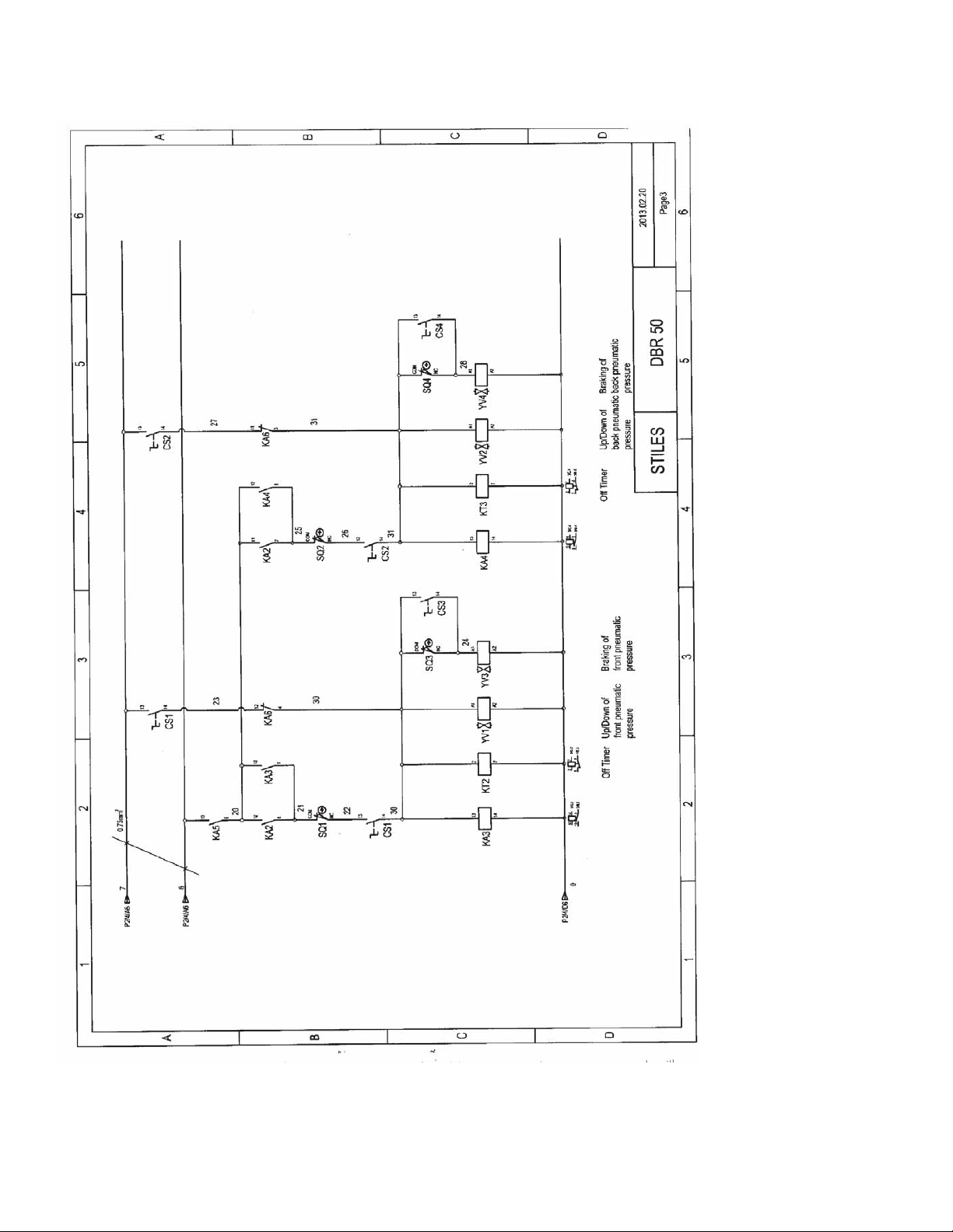
9.2 Electrical Diagram (Continued)
Ironwood DBR50 | User Manual 23
Page 24
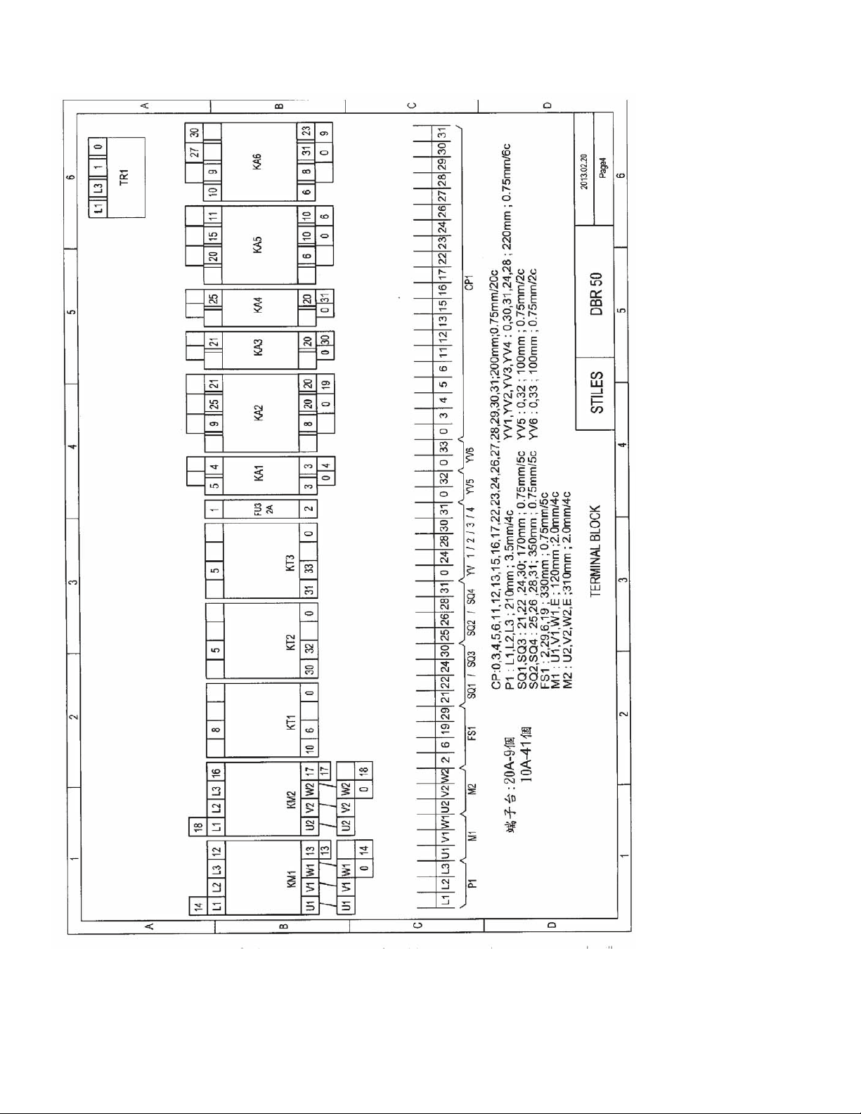
9.2 Electrical Diagram (Continued)
Ironwood DBR50 | User Manual24
Page 25

Page 26
Version A
0
0
0
0
0
0
0
0
0
0
0
0
0
0
0
September 2013
© 2013 Stiles Machinery Inc.
Stiles Machinery Inc.
3965 44th St. SE
Grand Rapids, MI 49512
p. 616.698.7500
f. 616.698.9411
www.stilesmachinery.com
 Loading...