

Iron Rival IR-10-B, IR-13-B, IR-8-F, IR-10-F Owner's Manual & Installation Manual
OWNER’S MANUAL &
INSTALLATION GUIDE
Applicable Models:
IR-10-B | IR-13-B | IR-8-F | IR-10-F
PLEASE READ THIS MANUAL CAREFULLY
BEFORE ATTEMPTING INSTALLATION
FAILURE TO FOLLOW THESE INSTRUCTIONS
MAY VOID YOUR WARRANTY.

Congratulations on the purchase of your Iron Rival Series water treatment system. You have
purchased one of the finest iron treatment systems on the market today. The Iron Rival Series water
treatment system uses a multi-faceted treatment process consisting of a combination of aeration,
oxidation, and filtration for the reduction/removal of iron, manganese, and hydrogen sulfide from
your water supply.
This manual is designed to provide owners, installers, and service technicians with detailed
information about the installation, start-up, and operation of your new filter system.
The heart of your Iron Rival System is the Fleck 2510SXT control valve. It is manufactured by one
of the world’s largest water treatment companies. The Fleck 2510 control valve is well respected
for its reliability, serviceability, simple operation, and value. The integrated Fleck SXT digital
valve controller offers unsurpassed simplicity of operation, yet complete control over all important
valve operations. You can rest assured that you have made a solid investment in the quality of your
water supply!
Once installed and correctly set-up, your Iron Rival water treatment system is designed to offer low
maintenance operation. The control valve will perform regular backwash and regeneration
functions automatically. For your convenience, your system has been pre-programmed for you by
our technicians. Should you need to change any of the settings, simply following the instructions
provided in this manual.
Table of Contents:
OPERATING CONDITIONS …………………………………………………... 3
INSTALLATION …………………………………………………………..……. 4
Step 1 – Pre-Installation Inspection ………………………………….…… 4
Step 2 – Select an installation Site …………………………………..…... 4
Step 3 – Prepare Treatment Tank ………………………………………… 5
Step 4 – Turn off the Water & Electric Water Heaters ………………..… 7
Step 5 – Prepare and Install Inlet and Outlet Plumbing Connections ….... 7
Step 6 – Drain Line Installation ……………………………………….… 9
Step 7 – Control Valve Set-up …………………………………………... 10
Step 8 – Initial Start-up and Leak Testing ………………………………. 11
REGENERATION ………………………………………………………………. 13
CHANGING TIME OF DAY …………………………………………………… 14
USER PROGRAMMING MODE ………………………………………………. 14
MASTER PROGRAMMING MODE …………………………………………… 15
RESETS ……………………………………………………….………………… 16
CONTROL OPERATION DURING A POWER FAILURE …………………… 16
MAINTENANCE & TROUBLESHOOTING……………………………………. 17
WARRANTY INFORMATION ………………………………………………… 18
2

OPERATING CONDITIONS
The following chart provides guidance on the operating conditions required for successful operation
of your Iron Rival system. Use of this equipment outside of these operating conditions may
adversely affect the performance of your system, result in system damage including water leaks and
resulting property damage, and may void your warranty.
Iron Rival
IR-10-B
Catalyst Media Used BIRM BIRM FILOX FILOX
Pre-Oxidation by Captive
Air Charge?
Tank Size 10 x 54 13 x 54 4 x 44 10 x 54
Media Volume 1.0 CF 1.5 CF 0.5 CF 1.0 CF
Maximum Water
Pressure
Minimum Water Pressure 30 PSI 30 PSI 30 PSI* 30 PSI
Optimal Water Pressure 40-65 PSI 40-65 PSI 40-65 PSI 40-65 PSI
Maximum Water
Temperature
Minimum Air
Temperature
pH Range 6.8 to 9.0 6.8 to 9.0 5.0*** to 9.0 5.0*** to 9.0
Maximum Iron Up to 5 ppm Up to10 ppm Up to 10 ppm Up to 20 ppm
Maximum Manganese Up to1 ppm**** Up to1 ppm**** Up to 2 ppm Up to 5 ppm
Max. Hydrogen Sulfide not recommended not recommended Up to 5 ppm Up to10 ppm
Max. (Peak) Flow Rate 7.5 GPM 11 GPM 6 GPM 12 GPM
Service Flow Rate 5 GPM 8 GPM 5 GPM 8.5 GPM
Backwash Flow Rate
Cold Water <60F
Warm Water >60F
Backwash Frequency Every 3 days Every 3 days Daily Daily
Yes Yes Yes Yes
70 PSI* 70 PSI* 70 PSI* 70 PSI*
110°F (43°C) 110°F (43°C) 110°F (43°C) 110°F (43°C)
32°F (0°C)** 32°F (0°C)** 32°F (0°C)** 32°F (0°C)**
5 GPM
7 GPM
Iron Rival
IR-13-B
9 GPM
11 GPM
Iron Rival
IR-8-F
5 GPM
8 GPM
Iron Rival
IR-10-F
8 GPM
11 GPM
* if your home water pressure is greater than 70 PSI, you should have a pressure reduction valve installed by a certified
plumber prior to installing this product.
** the unit cannot be subjected to freezing conditions or severe damage to the system and/or your property could occur.
*** pH correction is recommended where pH levels are less than 6.5 to prevent damage to your plumbing system and
potential leaching of metals from copper and brass plumbing components and solder. Contact your dealer for
recommendations.
**** but only if pH is 8.0 to 8.5 and iron to manganese ratio is 10:1 or higher
Service flow rates are based on contaminant levels not exceeding 50% of the stated levels above.
Reduce service flow rate expectations as contaminant levels rise above this threshold, particularly if
they are approaching the stated levels above.
CONFIRM THAT YOUR WATER CONDITIONS AND AVAILABLE
BACKWASH FLOW RATES MEET THE ABOVE SPECIFICATIONS FOR
THE MODEL YOU ARE INSTALLING BEFORE COMMENCING THE
INSTALLATION PROCESS. IF IN DOUBT, CALL YOUR DEALER FOR
ADVICE. INSTALLED UNITS CANNOT BE RETURNED.
3
INSTALLATION
We recommend that you read the entire instructions before commencing the actual
installation. While we strongly recommend that a licensed plumber perform all installation
work, a mechanically-inclined homeowner can install an Iron Rival system. In all cases, it is
critical that the installation be done in accordance with these instructions and all applicable
plumbing and electrical codes. Be sure to obtain all required permits. If these instructions
and the applicable codes are in conflict, the relevant plumbing/electrical code shall be
followed. Equipment failure, personal injury, or property damage can result if this
equipment is not installed properly.
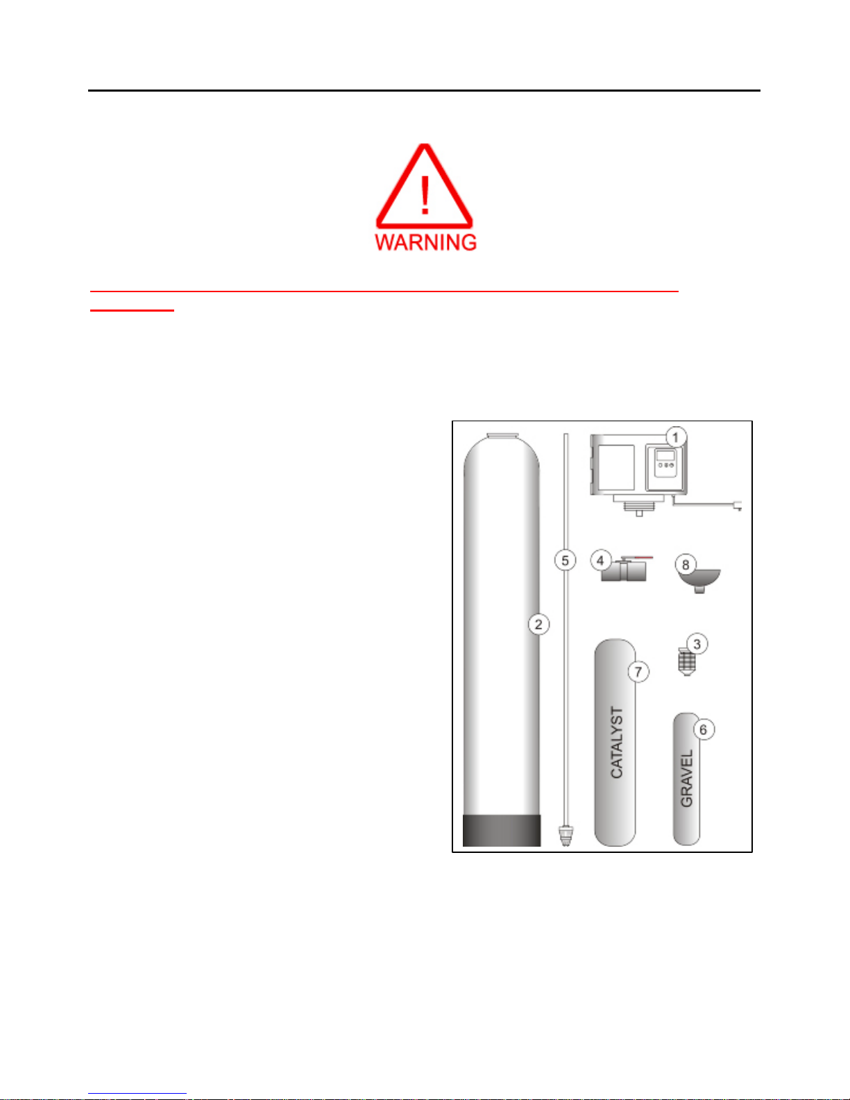
Step 1. – Pre-Installation Inspection
Inspect all of the components that you received with
your unit. You should have received the following:
1. Fleck 2510XST Control Valve
2. Treatment Tank
3. Upper Locking Stack Diffuser
4. Bypass
5. Riser tube and lower distributor
6. Bag or box of gravel
7. Bag or box of catalyst media (Birm or Filox)
8. Funnel
You may have also received a tank cover/jacket kit
if you ordered this option with your system.
Step 2. – Selecting an Installation Location
We recommend interior installation only. The
system cannot be allowed to freeze or severe system
damage could occur. The system should not be installed in direct sunlight as long-term exposure to
UV light could damage components of the system. Furthermore, direct sunlight could raise the
internal water temperature in the treatment tank and reduce backwash effectiveness. In most cases,
the Iron Rival should be located AFTER the expansion tank and sediment pre-filters (if applicable),
and BEFORE a water softener, carbon filters, and/or ultraviolet (UV) sterilizer (if applicable), and
the hot water heater. If possible, it is also generally desirable to place the Iron Rival AFTER the
plumbing branch off to your outdoor irrigation water.
4

Select a location for installation of your Iron Rival that is within close proximity to the main
incoming water lines of the home. The location should have a firm, level surface with sufficient
space for the treatment tank. Ensure that there will be sufficient space surrounding the unit to
facilitate maintenance.
You will also need access to a standard, non-switched, grounded 120volt (60 Hz) electrical outlet.
The Fleck 2510SXT control valve comes with a 5 foot long electrical cord. An extension cord may
be used to reach a suitable electrical outlet. If this option is used, ensure that the extension cord is
UL/CSA certified and of an appropriate wire gauge for the application.
You will also require a nearby floor drain or standpipe to discharge the drain water from the
backwash cycle (a drain standpipe for a washing machine, floor drain, or sump pump are excellent
drain options). We recommend that the drain line be connected to a minimum 1½" drain standpipe
or floor drain located ideally below the top of the head of your Iron Rival. If possible, the drain
should be no farther than 20 feet from the system.
Note: Never connect the drain line directly into a drain pipe. Allow an air gap between the drain
tubing and waste line to prevent the possibility of back-siphoning. We do not recommend use of a
check valve as it may become clogged with contaminants ejected from the system during backwash.
Step 3. – Prepare Treatment Tank
Two types of media are supplied with your Iron Rival system: washed gravel which forms the base
layer (underbedding) in your treatment tank, and specialized catalyst media (either Birm or Filox-R
depending on the model purchased), that promotes the rapid oxidation of the contaminants.
Before you start, gather the main treatment tank, the Fleck 2510SXT control valve, upper locking
stack diffuser, distributor and riser tube assembly (shipped inside the tank), funnel, and the bags or
boxes of gravel and catalyst media. Place the tank in the location where it will sit when the
installation is complete. Temporarily, remove the riser/tube distributor assembly from the treatment
tank. Hand tighten the Fleck 2510SXT control valve on the tank, and mark where the front of the
tank will be. Turn the tank so that the front of the tank is where you want it when it is full – once it
is full of media and water, it becomes very heavy and is hard to move!
Remove the controller and re-insert the distributor and riser tube assembly into the tank. The
distributor, which looks like a plastic screen, is pre-connected to the end of the long plastic riser
tube which extends from the bottom of the tank to the top of the tank where the control valve is
attached. At the bottom of the tank, there is a recess in the center of the tank to accept the
distributor to keep it aligned properly in the center of the tank. The riser tube has been pre-cut to
the correct height for you. When the distributor is correctly positioned, the top of the riser tube will
be almost perfectly flush with the top of the tank. If the tube is protruding above the tank, the
distributor tube is not nested correctly in the recess at the bottom of the tank.
Add enough water to the tank to cover the lower distributor with a minimum of 6 inches of water.
This will prevent damage to the lower distributor as gravel is loaded. Place the funnel into the tank
so that the riser tube is in the middle. Place tape over the open end of the riser tube. This will
prevent gravel or media from accidentally going down the tube during the following steps.
5
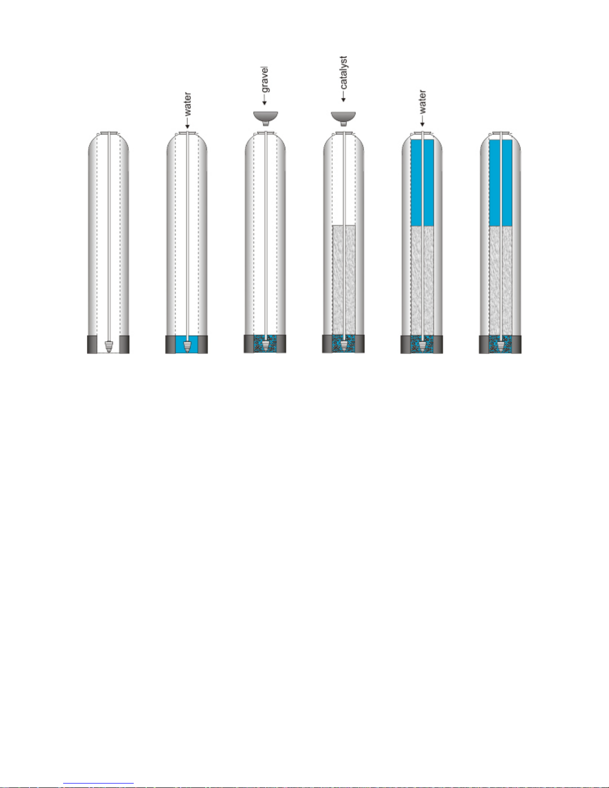
Take the bag/box of gravel and using a small scoop, add enough gravel to the tank through the
funnel to completely cover the distributor plus about 1 to 2 inches. Be sure to provide some
pressure on the riser tube while adding the gravel so as to ensure that the distributor does not shift
out of its recess. Ensure that you create an even layer of gravel across the bottom of the tank. A
rigid piece of thin wall tubing (conduit, copper pipe, etc.), approximately 1” longer than the tank
height works well as a leveling tool. As the tank fills, ensure that the riser tube remains centered in
the opening at the top of the tank.
Once this is complete, add the catalyst media in the same manner. Depending on the capacity of the
system, there will only be enough media to fill the tank to about 1/2 to 2/3 full. Use all of the
catalyst media provided. The treatment tank should never be filled to the top of the tank as the
remaining space, known as the “freeboard” is necessary for the media to have room to move during
the backwash cycle. Once the set-up is complete, the freeboard space will also contain a
pressurized pocket of air that provides aeration to begin the contaminant removal process.
Once you have finished adding the media to the tank, remove the tape from the distributor tube. Be
careful not to pull upwards on the riser tube while doing this as it is important that the distributor
remain in its recess at the bottom of the tank.
Fill the treatment tank with water up to within a couple of inches of the top of the tank. This will
allow the media to pre-soak, thereby preventing media loss during the initial backwash.
If you purchased an optional tank jacket kit, install it now.
6
 Loading...